EP0545877B1 - Fahrzeug zum Stapeln von Lasten - Google Patents
Fahrzeug zum Stapeln von Lasten Download PDFInfo
- Publication number
- EP0545877B1 EP0545877B1 EP19920850273 EP92850273A EP0545877B1 EP 0545877 B1 EP0545877 B1 EP 0545877B1 EP 19920850273 EP19920850273 EP 19920850273 EP 92850273 A EP92850273 A EP 92850273A EP 0545877 B1 EP0545877 B1 EP 0545877B1
- Authority
- EP
- European Patent Office
- Prior art keywords
- driver
- place
- lifting
- load carrier
- hydraulic
- Prior art date
- Legal status (The legal status is an assumption and is not a legal conclusion. Google has not performed a legal analysis and makes no representation as to the accuracy of the status listed.)
- Expired - Lifetime
Links
Images

Classifications
-
- B—PERFORMING OPERATIONS; TRANSPORTING
- B66—HOISTING; LIFTING; HAULING
- B66F—HOISTING, LIFTING, HAULING OR PUSHING, NOT OTHERWISE PROVIDED FOR, e.g. DEVICES WHICH APPLY A LIFTING OR PUSHING FORCE DIRECTLY TO THE SURFACE OF A LOAD
- B66F9/00—Devices for lifting or lowering bulky or heavy goods for loading or unloading purposes
- B66F9/06—Devices for lifting or lowering bulky or heavy goods for loading or unloading purposes movable, with their loads, on wheels or the like, e.g. fork-lift trucks
- B66F9/075—Constructional features or details
- B66F9/07545—Overhead guards
Definitions
- the present invention relates to a sliding frame truck for stacking loads at high heights, comprising a wheel-carried chassis which includes a lifting mast, a chassis-mounted drivers place positioned transversely to the drive direction, and a load-stacking load carrier which is movable along the mast and which can be manoeuvred from the driver's place for loading and offloading purposes.
- One type of lifting vehicle of the aforedefined kind is often referred to as a sliding frame truck, which is used for handling pallet-carried goods in storage locations.
- the goods are normally stacked on pallets and when the goods are to be shifted, the forks of the truck are brought into alignment with the pallet directly from the driver's place, by driving the truck to a correct position at right angles to the goods in question and raising or lowering the forks into the correct position for lifting/lowering the goods.
- Such trucks work at high lifting heights, often heights of up to 10-12 m, which requires a high degree of accuracy on the part of the truck driver.
- the driver's work is also made more difficult by the fact that a greater part of his forward vision is obstructed by the truck frame or the mast, which must be powerfully dimensioned because of the high lifting heights involved. Furthermore, such storage locations are poorly illuminated, in order to cut down on costs. Although this poor lighting can be compensated for by fitting headlamps to the fork assembly, there are many instances when headlamps are not provided, despite the poor visibility.
- Another problem connected with positioning the fork assembly is that the driver's place is situated at right angles to the longitudinal axis of the truck and therewith also at right angles to the length extension of the forks.
- one object of the present invention is to provide a lifting vehicle of the kind defined in the introduction with which problems associated with uncomfortable inclination of the driver's head and poor visibility are avoided to a significant extent. Further objects of the invention and advantages afforded thereby will be apparent from the following description. These objects and advantages are realized by a lifting vehicle having the characteristic features set forth in the following claims.
- the present invention provides a lifting vehicle of the aforedescribed kind which includes a tilting means which function to tilt the driver's place in relation to the chassis between a normal vehicle driving position and a rearward tilted position for high lifts, about a tilting axle which is generally parallel with the longitudinal axis of the vehicle, and located behind the drivers seat.
- tilting of the driver's place and the height to which the load carrier is lifted may be mutually coordinated and, although not necessarily, made directly proportional so that the driver's place will be tilted to a maximum at the time the load reaches its highest position.
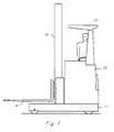
- the illustrated vehicle is an industrial fork-lift truck, and more specifically a sliding frame truck of the kind mentioned in the introductory part of this specification.
- the truck includes conventionally a wheel-carried chassis 11, a chassis-mounted lifting mast 12 and a driver's place 13 which is transversal to the longitudinal axis of the vehicle.
- the lifting most 12 or the frame is normally comprised of two or more telescopically arranged sections 14 and a load carrier 15 in the form of a lifting fork, which can be moved along the full length of the lifting mast.
- the lifting fork 15 extends in the direction of the vehicle long axis and is intended to carry palleted loads 16.
- the driver's place 13 of the illustrated embodiment includes a cabin-like construction which accommodates a driver's seat 17, a steering wheel 18 and other steering controls for manouvering the truck, and a driver protection frame structure 19.
- the driver is placed so as to sit at right angles to the longitudinal axis of the truck and to the direction in which the truck is driven, and therewith also to the forward direction of the load carrying fork 15.
- the entire driver's place or cabin 13 can be tilted about a tilting axle 20 by means of a tilting device 21, in the form of some appropriate lifting device.
- the tilting axle 20 is placed rearwardly of the driver's seat 17 and extends along one long side of the truck.
- the lifting device 21 will conveniently have the form of a hydraulic piston-cylinder device mounted between a first linch pin 22 mounted on the chassis and another linch pin 23 mounted on the cabin structure, in front of the driver.
- the driver's place is tilted rearwardly at an angle of 30-40°, to the position shown in Figure 3, this figure also showing that the driver's head will then be located outside the plane of the long side of the truck, therewith affording the driver a better viewing angle without troublesome bending of the head.
- the tipping device 21 may also have the form of some other type of hydraulic motor, or alternatively of some form of drive motor mounted in connection with the tilting axle 20, such that the rotary shaft of the motor and the tilting axle will essentially coincide.
- the arrangement may also include guide means which function to adjust automatically the rearwardly inclined position of the driver's place in relation to the height to which the load carrier is raised. This setting, or adjustment, need not be directly proportional, but may vary from case to case, so that different drivers are afforded the best possible comfort.
- This automatic accompanyment of the hydraulic lifting device may conceivably be achieved by coupling a hydraulic pump in parallel with the hydraulic pump conventionally provided with delivering working fluid to the lifting piston-cylinder devices (not shown) of the load carrier or fork 15.
- the additional pump may be given a capacity in which the driver's place will be tilted rearwardly to a maximum when the load carrier has reached its highest point.
- the lifting device may comprise a motor-driven ball screw and the tilting movement of the driver's place can be combined in some suitable manner with means which will enable the whole or parts of the driver's place to be swung to one side.
Landscapes
- Engineering & Computer Science (AREA)
- Transportation (AREA)
- Structural Engineering (AREA)
- Civil Engineering (AREA)
- Life Sciences & Earth Sciences (AREA)
- Geology (AREA)
- Mechanical Engineering (AREA)
- Forklifts And Lifting Vehicles (AREA)
Claims (4)
- Schlitten-Lasttransportwagen zum Stapeln von Lasten (16) auf große Höhen, welcher ein auf Rädern laufendes Fahrgestell hat, welches einen Hubmast (12), einen am Fahrgestell angebrachten Fuhrerstand (13), welcher in Querrichtung zur Fahrtrichtung angeordnet ist, und einen laststapelnden Lastträger (15) umfaßt, welcher entlang des Masts bewegbar ist, und der vom Führerstand (13) aus zum Be- und Entladen bedienbar ist, gekennzeichnet durch eine Kippeinrichtung (21), welche derart arbeitet, daß sie den Führerstand (13) bezüglich des Fahrgestells (11) zwischen einer normalen Fahrzeugfahrtposition und einer nach hinten gekippten Position für große Hubhöhen um eine Kippachse (20) bewegt ist, welche im allgemeinen parallel zur Längsachse des Fahrzeugs ist und hinter dem Fahrersitz (17) liegt.
- Hubfahrzeug nach Anspruch 1, dadurch gekennzeichnet, daß eine Hubeinrichtung vorgesehen ist, welche derart eingerichtet ist, daß sie das vordere Ende der Kabine mit Hilfe einer hydraulischen Kolben-Zylinder-Einrichtung anhebt, welche mit einer Hydraulikschaltung verbuden oder koordiniert ist, welche zum Heben und Senken des Lastträgers (15) eingesetzt wird.
- Hubfahrzeug nach Anspruch 1 oder 2, gekennzeichnet durch eine Steuereinrichtung zum automatischen Einstellen der rückwärts gerichteten Kippbewegung des Führerstandes (13) in Abhängigkeit von der Höhe, auf die der Lastträger angehoben wird.
- Hubfahrzeug nach Anspruch 2 oder 3, gekennzeichnet durch eine erste Hydraulikpumpe zum Betreiben des Hydraulikkreises zum Heben und Senken des Lastträgers (15), und eine zweite Hydraulikpumpe, welche parallel zu der ersten Hydraulikpumpe geschaltet ist und derart arbeitet, daß Arbeitsfluid der hydraulischen Kolben-Zylindereinrichtung der Hubeinrichtung (21) oder dem Hydraulikmotor zugeleitet wird, wobei das Leistungsvermögen der zweiten Pumpe derart angepaßt ist, daß der Führerstand (13) nach hinten auf einen Maximalwert gekippt wird, wenn der Lastträger zur höchsten Position angehoben wird.
Applications Claiming Priority (2)
| Application Number | Priority Date | Filing Date | Title |
|---|---|---|---|
| SE9103390A SE469426B (sv) | 1991-11-18 | 1991-11-18 | Skjutstativtruck med lutningsbar foerarplats |
| SE9103390 | 1991-11-18 |
Publications (2)
| Publication Number | Publication Date |
|---|---|
| EP0545877A1 EP0545877A1 (de) | 1993-06-09 |
| EP0545877B1 true EP0545877B1 (de) | 1997-10-15 |
Family
ID=20384345
Family Applications (1)
| Application Number | Title | Priority Date | Filing Date |
|---|---|---|---|
| EP19920850273 Expired - Lifetime EP0545877B1 (de) | 1991-11-18 | 1992-11-18 | Fahrzeug zum Stapeln von Lasten |
Country Status (3)
| Country | Link |
|---|---|
| EP (1) | EP0545877B1 (de) |
| DE (1) | DE69222738T2 (de) |
| SE (1) | SE469426B (de) |
Families Citing this family (8)
| Publication number | Priority date | Publication date | Assignee | Title |
|---|---|---|---|---|
| SE510807C2 (sv) * | 1994-10-07 | 1999-06-28 | Bt Ind Ab | Tiltanordning vid truckhytt |
| DE19524319C2 (de) * | 1995-07-04 | 1999-12-30 | Jungheinrich Ag | Bedienerkabine für ein Stapelfahrzeug |
| EP1129983A3 (de) * | 2000-03-01 | 2004-07-07 | Fiat OM Carrelli Elevatori S.p.A. | Flurförderzeug mit einer Hubvorrichtung |
| EP1129981A3 (de) * | 2000-03-01 | 2004-01-21 | Fiat OM Carrelli Elevatori S.p.A. | Flurförderzeug mit einer Fahrerkabine |
| FR2850942B1 (fr) * | 2003-02-11 | 2006-02-17 | Renault Vehicules Ind | Cabine a poste de conduite pour vehicule a moteur |
| GB0521649D0 (en) | 2005-10-24 | 2006-03-29 | Strachan & Henshaw Ltd | A payload deployment system |
| FR2990202B1 (fr) * | 2012-05-04 | 2015-01-30 | Manitou Bf | Machine automotrice de levage |
| CN112551435B (zh) * | 2019-09-10 | 2022-05-13 | 比亚迪股份有限公司 | 叉车 |
Family Cites Families (10)
| Publication number | Priority date | Publication date | Assignee | Title |
|---|---|---|---|---|
| US3595409A (en) * | 1968-05-09 | 1971-07-27 | Lancer Boss Ltd | Side loader vehicles |
| US4120375A (en) * | 1976-04-15 | 1978-10-17 | Kabushiki Kaisha Toyoda Jidoshokki Seisakusho | Tiltable cab construction for an industrial vehicle |
| US4331419A (en) * | 1980-04-21 | 1982-05-25 | Scott S. Corbett, Jr. | Storage system for cargo container trailers |
| US4436169A (en) * | 1982-01-25 | 1984-03-13 | Fmc Corporation | Elevating and tilting mechanism for crane cab |
| SE446622B (sv) * | 1984-12-03 | 1986-09-29 | Kalmar Last Maskin Verkstad Ab | Anordning vid en motordriven truck |
| US4747319A (en) * | 1985-12-16 | 1988-05-31 | Jidosha Kiki Co., Ltd. | Actuator |
| DE3602762A1 (de) * | 1986-01-30 | 1987-08-06 | Claas Ohg | Flurfoerderzug |
| DE3904225A1 (de) * | 1989-02-13 | 1990-08-16 | Schlueter Anton Muenchen Gmbh | Schlepper, insbesondere fuer landwirtschaftlichen einsatz stichwort: kippbare kabine |
| NO169166C (no) * | 1989-09-25 | 1992-05-20 | Borgar Brubakken | Anordning ved gaffeltruck |
| FR2664556B1 (fr) * | 1990-07-10 | 1993-07-30 | Brissaud Dominique | Engin de manutention a cabine tournante. |
-
1991
- 1991-11-18 SE SE9103390A patent/SE469426B/sv not_active IP Right Cessation
-
1992
- 1992-11-18 DE DE1992622738 patent/DE69222738T2/de not_active Expired - Lifetime
- 1992-11-18 EP EP19920850273 patent/EP0545877B1/de not_active Expired - Lifetime
Also Published As
| Publication number | Publication date |
|---|---|
| SE9103390D0 (sv) | 1991-11-18 |
| SE9103390L (sv) | 1993-05-19 |
| EP0545877A1 (de) | 1993-06-09 |
| SE469426B (sv) | 1993-07-05 |
| DE69222738D1 (de) | 1997-11-20 |
| DE69222738T2 (de) | 1998-02-12 |
Similar Documents
| Publication | Publication Date | Title |
|---|---|---|
| EP2342155B1 (de) | Gabelträger für förderahrzeug | |
| EP2035318B1 (de) | Overhead-schutz für ein materialienfahrzeug | |
| CA1290317C (en) | Mobile lifting apparatus | |
| CA2524093C (en) | Fork lift truck | |
| EP0870727B1 (de) | Seitenstapler mit drehbarer Kabine | |
| EP0545877A1 (de) | Fahrzeug zum Stapeln von Lasten | |
| EP0298712B1 (de) | Lasthandhabungsfahrzeuge | |
| GB2356624A (en) | Improved stability fork-lift truck | |
| US4436183A (en) | Material handling apparatus | |
| US6079935A (en) | Forklift truck | |
| CA1160997A (en) | Multiple section mast with a pair of lift jacks behind the primary section uprights | |
| EP0543791A1 (de) | Hubfahrzeug zur Lagerung von Lasten | |
| US12077422B2 (en) | Device for transporting a transport item, and method | |
| GB2264689A (en) | Load handling truck | |
| US5320197A (en) | Sextuple upright | |
| US6439827B1 (en) | Load handling vehicle | |
| GB2279934A (en) | A device for transporting a load | |
| US4101040A (en) | Vehicle for transporting palletized loads | |
| US6050367A (en) | Bi-directional vehicle | |
| JP2508910Y2 (ja) | フォ―クリフトトラックの速度制御装置 | |
| WO1991014050A1 (en) | Dumper | |
| US20030108413A1 (en) | Load lifting attachment for skid-steer loader | |
| EP4458754A1 (de) | Hubfahrzeug mit kippbarem fahrerhaus | |
| GB2327077A (en) | Compact load handling vehicle | |
| AU742698B2 (en) | Improvements in fork lifts |
Legal Events
| Date | Code | Title | Description |
|---|---|---|---|
| PUAI | Public reference made under article 153(3) epc to a published international application that has entered the european phase |
Free format text: ORIGINAL CODE: 0009012 |
|
| AK | Designated contracting states |
Kind code of ref document: A1 Designated state(s): BE DE FR GB NL |
|
| 17P | Request for examination filed |
Effective date: 19931129 |
|
| 17Q | First examination report despatched |
Effective date: 19950112 |
|
| GRAG | Despatch of communication of intention to grant |
Free format text: ORIGINAL CODE: EPIDOS AGRA |
|
| GRAH | Despatch of communication of intention to grant a patent |
Free format text: ORIGINAL CODE: EPIDOS IGRA |
|
| GRAH | Despatch of communication of intention to grant a patent |
Free format text: ORIGINAL CODE: EPIDOS IGRA |
|
| GRAA | (expected) grant |
Free format text: ORIGINAL CODE: 0009210 |
|
| AK | Designated contracting states |
Kind code of ref document: B1 Designated state(s): BE DE FR GB NL |
|
| REF | Corresponds to: |
Ref document number: 69222738 Country of ref document: DE Date of ref document: 19971120 |
|
| ET | Fr: translation filed | ||
| PLBE | No opposition filed within time limit |
Free format text: ORIGINAL CODE: 0009261 |
|
| 26N | No opposition filed | ||
| REG | Reference to a national code |
Ref country code: GB Ref legal event code: IF02 |
|
| PGFP | Annual fee paid to national office [announced via postgrant information from national office to epo] |
Ref country code: NL Payment date: 20081125 Year of fee payment: 17 |
|
| PGFP | Annual fee paid to national office [announced via postgrant information from national office to epo] |
Ref country code: BE Payment date: 20090402 Year of fee payment: 17 |
|
| BERE | Be: lapsed |
Owner name: *BT INDUSTRIES A.B. Effective date: 20091130 |
|
| REG | Reference to a national code |
Ref country code: NL Ref legal event code: V1 Effective date: 20100601 |
|
| PG25 | Lapsed in a contracting state [announced via postgrant information from national office to epo] |
Ref country code: NL Free format text: LAPSE BECAUSE OF NON-PAYMENT OF DUE FEES Effective date: 20100601 Ref country code: BE Free format text: LAPSE BECAUSE OF NON-PAYMENT OF DUE FEES Effective date: 20091130 |
|
| PGFP | Annual fee paid to national office [announced via postgrant information from national office to epo] |
Ref country code: DE Payment date: 20101126 Year of fee payment: 19 |
|
| PGFP | Annual fee paid to national office [announced via postgrant information from national office to epo] |
Ref country code: GB Payment date: 20101130 Year of fee payment: 19 |
|
| PGFP | Annual fee paid to national office [announced via postgrant information from national office to epo] |
Ref country code: FR Payment date: 20120106 Year of fee payment: 20 |
|
| REG | Reference to a national code |
Ref country code: DE Ref legal event code: R071 Ref document number: 69222738 Country of ref document: DE |
|
| REG | Reference to a national code |
Ref country code: DE Ref legal event code: R071 Ref document number: 69222738 Country of ref document: DE |
|
| REG | Reference to a national code |
Ref country code: GB Ref legal event code: PE20 Expiry date: 20121117 |
|
| PG25 | Lapsed in a contracting state [announced via postgrant information from national office to epo] |
Ref country code: GB Free format text: LAPSE BECAUSE OF EXPIRATION OF PROTECTION Effective date: 20121117 |