EP0545894A2 - Epandeur centrifuge - Google Patents
Epandeur centrifuge Download PDFInfo
- Publication number
- EP0545894A2 EP0545894A2 EP93100749A EP93100749A EP0545894A2 EP 0545894 A2 EP0545894 A2 EP 0545894A2 EP 93100749 A EP93100749 A EP 93100749A EP 93100749 A EP93100749 A EP 93100749A EP 0545894 A2 EP0545894 A2 EP 0545894A2
- Authority
- EP
- European Patent Office
- Prior art keywords
- centrifugal
- outlet openings
- fertilizer spreader
- disc
- fertilizer
- Prior art date
- Legal status (The legal status is an assumption and is not a legal conclusion. Google has not performed a legal analysis and makes no representation as to the accuracy of the status listed.)
- Granted
Links
Images





Classifications
-
- A—HUMAN NECESSITIES
- A01—AGRICULTURE; FORESTRY; ANIMAL HUSBANDRY; HUNTING; TRAPPING; FISHING
- A01C—PLANTING; SOWING; FERTILISING
- A01C17/00—Fertilisers or seeders with centrifugal wheels
- A01C17/006—Regulating or dosing devices
- A01C17/008—Devices controlling the quantity or the distribution pattern
-
- Y—GENERAL TAGGING OF NEW TECHNOLOGICAL DEVELOPMENTS; GENERAL TAGGING OF CROSS-SECTIONAL TECHNOLOGIES SPANNING OVER SEVERAL SECTIONS OF THE IPC; TECHNICAL SUBJECTS COVERED BY FORMER USPC CROSS-REFERENCE ART COLLECTIONS [XRACs] AND DIGESTS
- Y02—TECHNOLOGIES OR APPLICATIONS FOR MITIGATION OR ADAPTATION AGAINST CLIMATE CHANGE
- Y02P—CLIMATE CHANGE MITIGATION TECHNOLOGIES IN THE PRODUCTION OR PROCESSING OF GOODS
- Y02P60/00—Technologies relating to agriculture, livestock or agroalimentary industries
- Y02P60/20—Reduction of greenhouse gas [GHG] emissions in agriculture, e.g. CO2
- Y02P60/21—Dinitrogen oxide [N2O], e.g. using aquaponics, hydroponics or efficiency measures
Definitions
- the invention relates to a centrifugal fertilizer broadcaster according to the preamble of patent claim 1.
- centrifugal fertilizer broadcaster is known, for example, from German Offenlegungsschrift 15 82 091.
- This centrifugal fertilizer spreader has a storage container, under the lower area of which two centrifugal disks are arranged side by side.
- Each centrifugal disc is assigned two metering elements which are arranged in the bottom of the storage container and which are designed as outlet openings through which the fertilizer is fed to the centrifugal discs at predetermined feed points.
- the fertilizer particles located in the storage container are supplied to each centrifugal disc in a predetermined and adjustable manner via these two outlet openings, the fertilizer particles being applied to two feed points of each centrifugal disc.
- the outlet openings assigned to the centrifugal disks are adjusted simultaneously and in the same way to change the quantity of spreading material to be spread out, by means of coupled rods, the so-called spreading quantity setting device.
- the coupling of the linkage assigned to the metering elements to the common spreading quantity setting device causes the metering elements of each centrifugal disc in the sense of a corresponding enlargement or reduction of the size.
- the centrifugal discs are driven in opposite directions and have a symmetrical scatter pattern.
- the spreading sectors generated by the spreader discs can move as a whole depending on the set spreading quantity or also with another type of spreading material or the distribution of the spreading material quantities thrown in each sector can change, provision is made for setting the direction of the spreading sectors of the spinning discs.
- the spreading quantity adjustment device is movably and fixably mounted on the frame of the centrifugal fertilizer spreader, the position of the outlet openings in relation to the centrifugal disks can be adjusted simultaneously and in the same way to change the spread pattern.
- the aim is to achieve a spread pattern that is as uniform as possible over the entire area to be spread.
- the invention is therefore based on the object of creating the possibility of correcting the scatter pattern with the simplest measures.
- the position and assignment of the metering elements to one another can be adjusted independently of one another by arranging discharge chutes or funnels or the like below the discharge openings, and by the discharge ends of these elements being adjustable independently of one another in relation to the centrifugal disc in a horizontal plane.
- the arrangement of adjustable running chutes or funnels below the outlet openings also makes it possible to change the position and assignment of the several feed points assigned to one centrifugal disc and to set them independently of one another.
- the feed points of the fertilizer particles supplied to the centrifugal disc can thus be shifted on the centrifugal disc, so that it is also possible to correct the scatter pattern produced by the centrifugal discs due to the centrifuged fertilizer particles.
- these components can be set using scales or markings or the like.
- a slide is assigned to each outlet opening, that the slides assigned to each outlet opening are adjustable independently of one another, so that the application quantity per application point is independent to be able to vary from one another. It is then provided according to the invention that the slides assigned to a centrifugal disc can be adjusted as a function of one another in such a way that the size of the outlet openings can be set differently, but when adjusting the slides the sum of the application rate provided per se or the sum of the released cross section is the same is the sum of the cross-sections with the same size setting of the outlet openings.
- the outlet openings in the bottom of the storage container are adjustable relative to the axis of rotation of the centrifugal disc or the centrifugal discs, and the outlet openings are mutually adjustable and mutually adjustable in different positions.
- the centrifugal disks can be adjusted in two overlapping directions of movement relative to the outlet openings in the horizontal plane. This also makes it possible to change the fertilizer application points of the fertilizer trickling out of the storage container onto the centrifugal disks, with the application points of the fertilizer on the centrifugal disks now being adjusted by adjusting the centrifugal disc relative to the outlet openings arranged in the storage container bottom. It is then provided according to the invention that the gear of the centrifugal disc or the mounting of the centrifugal discs is attached to the frame of the centrifugal fertilizer spreader by means of a toggle joint. Thus, the bearing or the gear of the centrifugal disc can be adjusted in the horizontal and X-direction in the horizontal plane on the frame of the centrifugal fertilizer spreader.
- the position of the outlet openings arranged in the common plate can be adjusted simultaneously, but in different ways with respect to the axis of rotation of the centrifugal disc. This makes it possible to adjust the one feed surface differently or more than the other feed surface, by the respective position of the corresponding outlet openings to the axis of rotation of the centrifugal disc.
- the feed areas can be adjusted and adjusted very individually and independently of each other.
- a spread pattern correction can be carried out by, for example, feeding more or less fertilizer to the application area, which is responsible for the fertilizer accumulation or fertilizer reduction point.
- the application rate per outlet opening can therefore be changed independently of one another. Furthermore, it is also possible to close one of the outlet openings when dispensing the smallest quantities, so that the other outlet opening can then have a larger cross section than if both outlet openings were open. This avoids clogging of the outlet openings when applying small quantities of fertilizer per unit area in an extremely simple manner.
- the plate on which the outlet openings are arranged is articulated over a or several levers are attached to the machine frame, the levers being adjustable together with the plate relative to the container bottom.
- centrifugal fertilizer spreader is already known from German Offenlegungsschrift 15 82 091.
- This centrifugal fertilizer spreader has a storage container, under the lower area of which two centrifugal disks are arranged side by side.
- Each centrifugal disc is assigned two metering elements which are arranged in the bottom of the storage container and which are designed as outlet openings through which the fertilizer is fed to the centrifugal discs on predetermined application surfaces.
- the fertilizer particles located in the storage container are supplied to each centrifugal disc in a predetermined and adjustable manner via these outlet openings, the fertilizer particles being applied to two application surfaces per centrifugal disc.
- the outlet openings assigned to the centrifugal disks are adjusted simultaneously and in the same way to change the quantity of spreading material to be spread out, by means of coupled rods, the so-called spreading quantity setting device.
- the coupling of the linkage assigned to the metering elements to the common spreading quantity setting device has the effect that the metering elements of each centrifugal disc are adjusted jointly in the sense of a corresponding increase or decrease in the delivery quantities.
- the centrifugal disks are driven rotating in opposite directions and have a symmetrical spreading pattern.
- the spreading sectors generated by the spreader discs can move as a whole depending on the set spreading quantity or with a different type of spreading material or the distribution of the spreading material quantities thrown in each sector can change, provision is made for setting the direction of the spreading sectors of the spinning disc.
- the spreading quantity adjustment device is movably and fixably mounted on the frame of the centrifugal fertilizer spreader, the position of the outlet openings relative to the centrifugal disks can be adjusted simultaneously and in the same way to change the spreading pattern - by changing the application points .
- centrifugal fertilizer spreader when the spreading quantity setting device is pivoted, there is a common angular displacement of the spreading sectors of both centrifugal discs, and the spreading sectors of the centrifugal discs are influenced independently of one another, so that a very individual spread pattern correction for the individual spreading regions within the spread pattern is not possible.
- This disadvantage is remedied by the centrifugal fertilizer spreader equipped in accordance with the invention.
- the invention provides that the plate is fastened to the bottom of the container so that it can be rotated or pivoted with respect to the axis of rotation of the centrifugal disc.
- the invention provides that the plate in which the outlet openings or an additional slider is provided, is adjustable via two independent scales, so that the position of the outlet openings in relation to the centrifugal disc is adjustable. It is then further provided that the plurality of outlet openings assigned to each centrifugal disc can be adjusted together. With this joint adjustment, the independent entry and adjustment of the outlet openings of a centrifugal disc is maintained compared to the centrifugal fertilizer spreader according to DE-OS 15 82 091.
- the invention provides that the adjustment of the outlet openings or the adjustment of the position of the feed surfaces via a Remote control takes place.
- the adjustment and adjustment of the outlet openings or the position of the feed surfaces of the fertilizer particles supplied to the centrifugal disks can be carried out according to the invention by means of the remote control in such a way that the remote control is connected to a computer which detects the setting and the spreading result and regulates the setting of the centrifugal fertilizer spreader accordingly .
- the inlet and adjustment size of the outlet openings or the position of the application surfaces of the fertilizer flow on the centrifugal disks can be carried out in the simplest way, it being possible during the application process that the outlet cross-sections and the position are automatically and independently adjusted and adjusted the application areas for spreading correction taking into account the respective due to the nutrient supply to the area to be sprinkled.
- the adjustment of two or more outlet openings assigned to a centrifugal disc, independently of one another, the application surfaces of the fertilizer being variable, can be used both with centrifugal discs rotating about upright, preferably perpendicular axes, and also with forwards and inwards inclined to the direction of travel Carry out rotating centrifugal discs.
- the actuating elements 20 and 21 actuating the slides 14 and 15 are arranged between the slides 14 and 15 and the plate-shaped elements 9 and 10 having the outlet openings 12 and 13.
- the adjustment levers 22 and 23 associated with the slides 14 and 15 interact with the adjustment scale 24 or 25 arranged on the respective plate-shaped element 9 or 10.
- the stops 26 and 27, which can be adjusted in different positions, are fixed, against which the adjusting levers 22 and 23 of the slides 14 and 15 come to rest.
- the tension spring 28 and 29 is also arranged between the plate-shaped elements 9 and 10 and the slides 14 and 15, the tension spring 28 and 29 is also arranged.
- the position of the outlet openings 12 and 13 arranged in the plate-shaped elements 9 and 10 can be adjusted in the adjustment range of the two larger inlet openings 7 located in the base plate 6, so that the position and assignment of the two fertilizer application points assigned to a centrifugal disc 18 are relative to one another is changeable and adjustable independently of one another.
- the respective position of the outlet openings 12 and 13 with respect to the centrifugal disks 18 can be made in an exact manner by means of the position levers 9 'and 10' of the plate-shaped elements 9 and 10, which cooperate with the setting scale 11, so that the position of the respective drop point of the Fertilizer particles on the centrifugal disc 18 can be adjusted individually.
- the respective drop point is located approximately vertically below the respectively opened opening cross section 30 or 31 of the outlet openings 12 or 13.
- pivoting the plate-shaped elements 9 and 10 provided with the outlet openings 12 and 13, respectively, about the upright axis 8 can the location of the respective Adjust the outlet opening 12 or 13 in the simplest way independently of one another.
- This adjustment of the position of the respective outlet opening 12 or 13 relative to the centrifugal disks 18 makes it possible in the simplest way to regulate the scatter pattern of the fertilizer particles thrown off the centrifugal disks 18, for example, only in its inner region without changing the outer region. This creates a much higher setting accuracy.
- the metered quantities of the two outlet openings 12 and 13 can be set independently of one another or their opening cross-sections are to be closed or opened independently of one another.
- four metering quantities can thus only be set by opening or closing the outlet openings 12 or 13 by means of the slides 14 or 15. This makes it possible to reduce the working width on the left by about a quarter of the working width of the centrifugal fertilizer spreader, for example by switching off one of the four openings, for example the discharge opening responsible for the left outer area. Until now, it was only possible to reduce the total working width by half by spreading on one side.
- more or less fertilizer is supplied to the drop point, which is responsible for the fertilizer accumulation or fertilizer reduction site, by changing the opening width of the respective outlet opening 12 or 13 in a corresponding manner by means of the slides 14 or 15.
- a further correction and shifting of fertilizer accumulation or lack of fertilizer is possible in a very simple manner by a corresponding change in the position of the metering elements 12 or 13 relative to the centrifugal disks 18.
- the centrifugal fertilizer spreader has sensors for detecting the individual scatter sectors generated by the centrifugal disks 18, the recorded measured values of which are forwarded, for example, to an electronic control device.
- This electronic control device can in turn be coupled to the actuating elements 20 and 21 for the slides 14 and 15.
- the actuating devices for adjusting the position of the outlet openings 12 and 13 relative to the centrifugal disks 18 between the frame 1 of the centrifugal fertilizer spreader and the plate-shaped elements 9 and 10 the actuating devices for changing the position of the outlet openings 12 and 13 relative to the centrifugal disks 18, that is to say to adjust the fertilizer application points of the fertilizer trickling out of the storage container 2 through the outlet openings 12 and 13, is also connected to the electronic control device which is arranged, for example, on the battery tractor.
- FIG. 3 shows a pair of centrifugal discs with centrifugal discs 33 and 34, which can be mounted, for example, on the output shafts of gearbox 17 of the centrifugal fertilizer spreader according to FIG. 1 without tools.
- these two centrifugal disks 33 and 34 have throwing blades 35 and 36 of different lengths.
- These throwing blades 35 and 36 are pivotally mounted about the respective bolt 37 on the centrifugal disc 33 and 34, respectively.
- the respective fixing element 38 which can be pivoted in the region of the elongated hole 39, is used to set the different positions of the throwing blades 35 and 36.
- the respective position of the throwing vane 35 or 36 can be found in a spreading chart, the individual setting positions being set exactly by means of the setting scale 40 arranged on the centrifugal disks 33 and 34 in the region of the elongated hole 39.
- the advantages of this adjustment of the throwing blades for correcting the spreading pattern are described, for example, in EP-OS 02 92 873.
- the pivoting blades 41 are pivotably articulated on the throwing blades 35 and 36 in an upright plane, so that the throwing blades 35 and 36 centrifuged fertilizer particles are thrown upwards and fall softly from above into the growing crop.
- FIG. 4 shows a centrifugal fertilizer spreader with the frame 42 in which the storage container 43 is fastened.
- This reservoir 43 has the four funnel tips 44, with each funnel tip 44 being assigned the centrifugal disc 45.
- the driven stirring element 46 projects into each funnel tip 44.
- Disposed below the funnel tips 44 is the metering member 47, which consists of an outlet opening and a slide which can be adjusted and closed in different opening widths.
- the fertilizer particles flowing out of the interior of the storage container 43 to the centrifugal disks 45 in precisely adjustable amounts are distributed uniformly over the surface to be sprinkled by the throwing vanes 48 arranged on the centrifugal disks 45, the throwing vanes 48 dividing the fertilizer particles into four gaps which laterally adjoin one another and overlap Spread spreading sectors over the soil surface to be spread in a uniform spreading pattern.
- the metering elements 47 assigned to the centrifugal disks 45 can be adjusted and adjusted independently of one another.
- the throwing blades 48 are arranged on the centrifugal disks 45 such that they can be pivoted at an angle.
- the fertilizer supply to the two middle centrifugal disks 45 is interrupted by closing the corresponding outlet opening by means of the slide, so that only fertilizer particles are supplied to the outer centrifugal disks 45.
- the fertilizer particles could be dispensed by means of the four outlet openings 45, since the opening cross sections for four outlet openings are logically much smaller than if the fertilizer particles were only fed to the respective outer centrifugal disks 45 via two outlet openings.
- the respective position of the outlet opening relative to the two centrifugal discs 45 can of course be changed such that the two scattering sectors over which the fertilizer particles are thrown off the outer centrifugal discs 45 overlap in the desired manner, so that a scattering pattern of uniform scattering strength arises over the entire area to be spread.
- FIG. 5 shows a four-disc centrifugal fertilizer spreader with the storage container 49, which is equipped with the separating roof 50 in the middle.
- the stirring and / or conveying shaft 51 Arranged within the reservoir 49 is the stirring and / or conveying shaft 51, with which the fertilizer flows to the metering openings openings and the slide existing metering 52 is promoted.
- the metering elements 52 are each placed above the centrifugal disks 53.
- two coverable emptying openings 55 are provided, so that a very quick emptying for remaining quantities in the reservoir 49 is possible.
- centrifugal disks 56 designed as throwing elements according to FIG. 6 can be adjusted relative to the outlet openings 57 arranged in the bottom of the storage container, so that the application points of the fertilizer particles on the respective centrifugal disk 56 can be varied.
- the gear 58, on the output shaft 59 of which the centrifugal disc 56 is fastened are each adjustable by means of an adjustable articulated lever linkage 60 on the support frame 61 of the centrifugal fertilizer spreader in different positions with respect to the outlet openings 57, so that the respective fertilizer application point of the trickling out of the outlet openings 57 Fertilizer particles can be adjusted individually to the respective centrifugal disc 56.
- an adjusting device 62 between the frame 61 of the centrifugal fertilizer spreader and the adjusting lever 63 of the articulated lever linkage 60 and by means of an adjusting device 65 connecting the adjusting levers 63 and 64 is required.
- the adjustment devices 62 and 65 can be adjusted both manually and automatically.
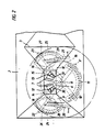
- FIG. 7 shows the centrifugal fertilizer spreader with the storage container 66.
- This storage container 66 is divided into two funnel-shaped container parts 68 by the roof-shaped central part 67. Below these funnel-shaped container parts 68, the base plate 69 is fastened, in each of which the two outlet openings assigned to a centrifugal disc 70 are arranged. Under these outlet openings, these outlet openings are arranged in slides which set and close different opening widths and which can be adjusted independently of one another for each outlet opening.
- the fertilizer particles trickling out of the outlet openings of the storage container in adjustable amounts by means of the slide first reach the outlet chutes 71 arranged below the outlet openings before they reach the centrifugal disks 70.
- the discharge ends 72 of these discharge chutes 71 can be adjusted independently of one another in relation to the centrifugal disc 70 in the horizontal plane, so that the application points with which the fertilizer particles strike the centrifugal disc 70 can be adjusted independently of one another.
- This adjustment of the outlet chutes 71 takes place on the basis of the scales 73 and 74, the feed point being adjusted in the X and Y directions in the horizontal plane relative to the respective centrifugal disc 70.
- Each outlet chute 71 is assigned an outlet opening, each of which has to be closed by a slide and the opening width of which has to be adjusted. This adjustment of the slide takes place independently of one another in order to be able to vary the feed quantity per feed point on the centrifugal disc 70 independently of one another.
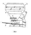
- the container attachment 75 is also placed on this storage container 66. So that the exact functioning of the metering elements of the centrifugal fertilizer spreader can now be checked by the tractor driver, it is provided with storage container 66 provided with this container attachment 75 that the front side 76 of the container attachment 75 is made transparent so that the tractor driver can see it in accordance with FIG. 9 into the interior of the storage container is very simple.
- the centrifugal fertilizer spreader has the frame 101 to which the storage container 102 is attached.
- the storage container 102 is divided by the roof-shaped central part 103 in such a way that the two funnel-shaped container parts 104 are formed.
- the base plate 106 which is easily exchangeably attached to the funnel, is arranged in the respective lower region 105 of these funnel-shaped container parts 104.
- the large outlet opening 107 is arranged in each of these plates 106.
- the slide plate 108 with the two outlet openings 109 is mounted so as to be pivotable relative to the plate 106 about the pivot point 110.
- the slide 111 which cooperates with the outlet openings 109, is fastened to this slide plate 108 so that it can pivot about the upright axis 112.
- the fertilizer particles located in the interior of the storage container 102 each arrive in adjustable amounts via the outlet openings 109 to the centrifugal disks 114 which are rotatably mounted in the gearboxes 13 below these outlet openings 109.
- These centrifugal disks 114 which can be driven in rotation, distribute the fertilizer particles added to them by means of the centrifugal disks 114 arranged on them Throwing blades 115 in an exact manner over the soil to be sprinkled surface.
- the centrifugal disks 114 are driven in a known and therefore not shown manner, for example by means of a propeller shaft from the PTO shaft of the agricultural tractor transporting the centrifugal fertilizer spreader and via gear arrangements.
- the centrifugal discs 114 can also be driven by oil motors. It is also possible for the centrifugal discs 114 to be driven in rotation about transversely to the direction of travel forward and about inwardly inclined axes 116.
- the slide plate 108 which is pivotally attached to the base plate 106 about the pivot point 110, interacts with the elongated hole guide 119 of the base plate 106, which has the scale 118, by means of the linkage 117 attached to the slide plate 108.
- the outlet openings 109 located in the slide plate 108 are articulated and fastened in an exactly adjustable manner to the machine frame of the centrifugal fertilizer spreader, so that the slide plate 108 can be adjusted in the region of the elongated hole guide 119 in relation to the container base formed as the base plate 106.
- the elongated hole 120 with the setting scale 121 is arranged in the slide plate 108.
- the stop element designed as a wing screw 122 is adjustably fastened, on which the lever arm 123 of the slide 111 comes to rest.
- the opening width of the outlet openings 109 can be set using the setting scale 121.
- the outlet openings 109 are closed by means of the slide 111 using the operating element designed as a hydraulic cylinder 124.
- the position of the application surfaces of the fertilizer stream flowing out of the outlet openings 109 onto the centrifugal discs 114 can be changed with respect to the axis of rotation 116 of the centrifugal discs 114 by pivoting the slide plate 108 about the pivot point 110 in the region of the elongated hole 119. Because the slide plate 108 with its outlet openings 109 and the slide 111 can be pivoted relative to one another, it is also possible to set the opening cross sections of the individual outlet openings 109 differently from one another.
- the base plate 106 with the slide plate 108 connecting rods 117 to be exchanged, for example by a remote control in the form of a hydraulic cylinder or the like, so that pivoting of the slide plate 108 about the pivot point 110 for shifting the feed surfaces of the flowing out of the outlet openings 109 Fertilizer flow on the centrifugal disc 114 is to be carried out by means of the remote control. It is also possible to change the stop 122 for the slide 111 using a remote control.
- FIG. 13 shows a further possibility for shifting the application areas of the fertilizer flows on the centrifugal disc 114.
- the outlet openings 125 can be set differently independently of one another in terms of their opening width.
- the setting slide 126 is set using two independent scales 127 and 128. Depending on the position of the setting slide 126, the ratio of the opening width of the outlet openings 125 to one another is set.
- the scale 128 is located on the holding arm 129 fixedly connected to the machine frame 101 of the centrifugal fertilizer spreader, on which the swivel lever 130, to which the scale 127 and the elongated hole 131 are fastened, can be swiveled relative to the holding arm 129 about the swivel axis 133. Furthermore, the lever arm 134 is engaged by the lever arm 134, which can be pivoted about the pivot point 133 and cooperates with the scale 128. On this lever arm 134, both the adjusting slide 126 and the slide 135 for opening and closing the outlet openings 125 are each pivotably connected to the lever arm 134 about the pivot axis 136. The outlet openings 125 are opened and closed by means of the slide 135 when the operating element 137, which acts as a hydraulic cylinder and engages on the holding arm 135, is actuated.
- the lever arm 134 is now pivoted about the pivot point 133, for example from B to E, then the right outlet opening 125 becomes faster larger than the left outlet opening 125 when adjusted according to scale 127, so more fertilizer will flow from the right outlet opening than from the left, which means that the outer region of the spreading sector sprinkled by the centrifugal disc 114 is supplied with more fertilizer than the inner region of the spreading sector.
- the outlet openings 138 are rotated about the pivot point 139 by means of the remote control device 140, which is located between the plate 141 in which the outlet openings 138 are arranged and engages the plate 142 of the container bottom.
- the outlet slide valve 143 which adjusts and closes the outlet openings 138 in different opening widths, is also fastened to this plate and can be pivoted about the pivot point 144 by means of the remote control device 145 for the different opening widths of the outlet openings 138 and for closing these outlet openings 138.
Landscapes
- Life Sciences & Earth Sciences (AREA)
- Soil Sciences (AREA)
- Environmental Sciences (AREA)
- Fertilizing (AREA)
Applications Claiming Priority (7)
| Application Number | Priority Date | Filing Date | Title |
|---|---|---|---|
| DE3911583A DE3911583A1 (de) | 1989-04-08 | 1989-04-08 | Schleuderduengerstreuer |
| DE3911582 | 1989-04-08 | ||
| DE3911583 | 1989-04-08 | ||
| DE3911582A DE3911582A1 (de) | 1989-04-08 | 1989-04-08 | Schleuderduengerstreuer |
| DE3933344 | 1989-10-06 | ||
| DE3933344A DE3933344A1 (de) | 1989-04-08 | 1989-10-06 | Schleuderduengerstreuer |
| EP19900106118 EP0392288A3 (fr) | 1989-04-08 | 1990-03-30 | Epandeur centrifuge |
Related Parent Applications (2)
| Application Number | Title | Priority Date | Filing Date |
|---|---|---|---|
| EP90106118.4 Division | 1990-03-30 | ||
| EP19900106118 Division EP0392288A3 (fr) | 1989-04-08 | 1990-03-30 | Epandeur centrifuge |
Publications (4)
| Publication Number | Publication Date |
|---|---|
| EP0545894A2 true EP0545894A2 (fr) | 1993-06-09 |
| EP0545894A3 EP0545894A3 (en) | 1993-07-14 |
| EP0545894B1 EP0545894B1 (fr) | 1998-07-08 |
| EP0545894B2 EP0545894B2 (fr) | 2002-12-11 |
Family
ID=27199381
Family Applications (2)
| Application Number | Title | Priority Date | Filing Date |
|---|---|---|---|
| EP93100749A Expired - Lifetime EP0545894B2 (fr) | 1989-04-08 | 1990-03-30 | Epandeur centrifuge |
| EP19900106118 Ceased EP0392288A3 (fr) | 1989-04-08 | 1990-03-30 | Epandeur centrifuge |
Family Applications After (1)
| Application Number | Title | Priority Date | Filing Date |
|---|---|---|---|
| EP19900106118 Ceased EP0392288A3 (fr) | 1989-04-08 | 1990-03-30 | Epandeur centrifuge |
Country Status (2)
| Country | Link |
|---|---|
| EP (2) | EP0545894B2 (fr) |
| DE (1) | DE59010835D1 (fr) |
Cited By (3)
| Publication number | Priority date | Publication date | Assignee | Title |
|---|---|---|---|---|
| EP0693251A1 (fr) * | 1994-07-22 | 1996-01-24 | Maasland N.V. | Outil pour épandre un matériau granuleux et/ou pulvérulent |
| WO1996032005A1 (fr) * | 1995-04-08 | 1996-10-17 | Amazonen-Werke H. Dreyer Gmbh & Co. Kg | Epandeur d'engrais centrifuge |
| EP2119336A1 (fr) * | 2008-05-14 | 2009-11-18 | Amazonen-Werke H. Dreyer GmbH & Co. KG | Dispositif de dosage |
Families Citing this family (9)
| Publication number | Priority date | Publication date | Assignee | Title |
|---|---|---|---|---|
| FR2673420B1 (fr) * | 1991-02-28 | 1995-09-01 | Sulky Burel Sa | Procede et dispositif pour regler a une valeur determinee la largeur d'epandage d'une machine d'epandage centrifuge de produits en grains. |
| DE4134317C2 (de) * | 1991-10-17 | 2003-05-15 | Amazonen Werke Dreyer H | Schleuderdüngerstreuer |
| DE59209403D1 (de) * | 1991-10-17 | 1998-08-13 | Amazonen Werke Dreyer H | Schleuderdüngerstreuer |
| EP0613613A1 (fr) * | 1993-02-27 | 1994-09-07 | Amazonen-Werke H. Dreyer GmbH & Co. KG | Epandeur centrifuge |
| DE10111553A1 (de) * | 2001-03-10 | 2002-09-12 | Rauch Landmaschfab Gmbh | Verfahren zum Verteilen von Streugut und Zentrifugalstreuer zur Durchführung des Verfahrens |
| DE10214652A1 (de) * | 2001-04-05 | 2002-10-10 | Rauch Landmaschfab Gmbh | Verfahren zum Verteilen von Streugut und Zentrifugalstreuer zur Durchführung des Verfahrens |
| DE102005015236A1 (de) | 2005-04-02 | 2006-10-05 | Rauch Landmaschinenfabrik Gmbh | Zweischeibenstreuer für Streugut, insbesondere Dünger, Salz oder dergleichen |
| DE102009026344A1 (de) * | 2009-08-07 | 2011-02-10 | Amazonen-Werke H. Dreyer Gmbh & Co. Kg | Zweischeibenstreuer |
| DE102010015954A1 (de) * | 2010-03-15 | 2011-09-15 | Amazonen-Werke H. Dreyer Gmbh & Co. Kg | Zweischeibenstreuer |
Family Cites Families (8)
| Publication number | Priority date | Publication date | Assignee | Title |
|---|---|---|---|---|
| FR596921A (fr) † | 1925-11-04 | |||
| FR621096A (fr) * | 1926-09-04 | 1927-05-04 | Dispositif d'orientation des goulottes pour le réglage de l'épandage dans les distributeurs à disques, d'engrais, de graines et de produits quelconques | |
| FR1532897A (fr) * | 1966-07-29 | 1968-07-12 | Ver Kunstmestf Mekog Albatros | Appareil centrifuge d'épandage muni de deux éléments distributeurs |
| AT301923B (de) * | 1970-10-13 | 1972-09-25 | Vogel & Noot Ag | Schleuderstreuer |
| FR2410427A1 (fr) * | 1977-12-05 | 1979-06-29 | Omab Sas Este Carla C | Dispositif epandeur ou distributeur d'engrais |
| IT1179621B (it) * | 1984-04-20 | 1987-09-16 | Andrea Ricca | Perfezionamento nella macchina spandiconcimi di ridotta portata |
| NL8701551A (nl) * | 1987-07-02 | 1989-02-01 | Lely Nv C Van Der | Machine voor het strooien van materiaal, zoals kunstmest. |
| DE3911584A1 (de) * | 1989-04-08 | 1990-10-11 | Amazonen Werke Dreyer H | Schleuderduengerstreuer |
-
1990
- 1990-03-30 EP EP93100749A patent/EP0545894B2/fr not_active Expired - Lifetime
- 1990-03-30 EP EP19900106118 patent/EP0392288A3/fr not_active Ceased
- 1990-03-30 DE DE59010835T patent/DE59010835D1/de not_active Expired - Fee Related
Cited By (5)
| Publication number | Priority date | Publication date | Assignee | Title |
|---|---|---|---|---|
| EP0693251A1 (fr) * | 1994-07-22 | 1996-01-24 | Maasland N.V. | Outil pour épandre un matériau granuleux et/ou pulvérulent |
| AU683756B2 (en) * | 1994-07-22 | 1997-11-20 | Maasland N.V. | An implement for spreading granular and/or pulverulent material |
| US6116526A (en) * | 1994-07-22 | 2000-09-12 | Maasland N,V. | Implement for spreading granular and/or pulverulent material |
| WO1996032005A1 (fr) * | 1995-04-08 | 1996-10-17 | Amazonen-Werke H. Dreyer Gmbh & Co. Kg | Epandeur d'engrais centrifuge |
| EP2119336A1 (fr) * | 2008-05-14 | 2009-11-18 | Amazonen-Werke H. Dreyer GmbH & Co. KG | Dispositif de dosage |
Also Published As
| Publication number | Publication date |
|---|---|
| EP0545894B2 (fr) | 2002-12-11 |
| EP0545894B1 (fr) | 1998-07-08 |
| EP0392288A2 (fr) | 1990-10-17 |
| DE59010835D1 (de) | 1998-08-13 |
| EP0392288A3 (fr) | 1991-01-16 |
| EP0545894A3 (en) | 1993-07-14 |
Similar Documents
| Publication | Publication Date | Title |
|---|---|---|
| EP0445842B1 (fr) | Distributeur d'engrais centrifuge avec trémie | |
| CH641318A5 (de) | Streugeraet fuer koerniges und/oder pulveriges gut. | |
| EP0545894A2 (fr) | Epandeur centrifuge | |
| EP0820219B1 (fr) | Epandeur d'engrais centrifuge | |
| EP0383071B1 (fr) | Epandeur centrifuge à grande largeur de travail | |
| EP0427936B1 (fr) | Epandeur d'engrais centrifuge | |
| EP0968639B1 (fr) | Epandeur centrifuge pour engrais | |
| EP0410312A1 (fr) | Distributeur centrifuge de matériaux granulaires, notamment d'engrais | |
| EP1031268B1 (fr) | Epandeur d'engrais centrifuge | |
| DE69107033T2 (de) | Verfahren und Vorrichtung zum Modifizieren des Spektrums eines Schleuderstreuers für körniges Material, um das Streuen auf den Feldrand zu ermöglichen. | |
| EP0392257B1 (fr) | Méthode de distribution d'engrais avec un épandeur centrifuge | |
| EP0292874B1 (fr) | Distributeur à grand tonnage | |
| DE3911583A1 (de) | Schleuderduengerstreuer | |
| EP0613613A1 (fr) | Epandeur centrifuge | |
| DE3911582A1 (de) | Schleuderduengerstreuer | |
| EP0504720B1 (fr) | Epandeur d'engrais centrifuge | |
| EP0379103A1 (fr) | Epandeur centrifuge | |
| DE3933344A1 (de) | Schleuderduengerstreuer | |
| DE4302802A1 (de) | Schleuderdüngerstreuer | |
| DE10047008A1 (de) | Zentrifugaldüngerstreuer | |
| DE19828713A1 (de) | Zentrifugaldüngerstreuer | |
| EP1190615A2 (fr) | Epandeur centrifuge pour engrais | |
| DE19802658A1 (de) | Verteilmaschine | |
| DE10033674A1 (de) | Schleuderdüngerstreuer | |
| DE4306204A1 (de) | Schleuderdüngerstreuer |
Legal Events
| Date | Code | Title | Description |
|---|---|---|---|
| PUAI | Public reference made under article 153(3) epc to a published international application that has entered the european phase |
Free format text: ORIGINAL CODE: 0009012 |
|
| PUAL | Search report despatched |
Free format text: ORIGINAL CODE: 0009013 |
|
| 17P | Request for examination filed |
Effective date: 19930120 |
|
| AC | Divisional application: reference to earlier application |
Ref document number: 392288 Country of ref document: EP |
|
| AK | Designated contracting states |
Kind code of ref document: A2 Designated state(s): DE FR GB NL |
|
| AK | Designated contracting states |
Kind code of ref document: A3 Designated state(s): DE FR GB NL |
|
| 17Q | First examination report despatched |
Effective date: 19950222 |
|
| GRAG | Despatch of communication of intention to grant |
Free format text: ORIGINAL CODE: EPIDOS AGRA |
|
| GRAG | Despatch of communication of intention to grant |
Free format text: ORIGINAL CODE: EPIDOS AGRA |
|
| GRAH | Despatch of communication of intention to grant a patent |
Free format text: ORIGINAL CODE: EPIDOS IGRA |
|
| GRAH | Despatch of communication of intention to grant a patent |
Free format text: ORIGINAL CODE: EPIDOS IGRA |
|
| GRAA | (expected) grant |
Free format text: ORIGINAL CODE: 0009210 |
|
| AC | Divisional application: reference to earlier application |
Ref document number: 392288 Country of ref document: EP |
|
| AK | Designated contracting states |
Kind code of ref document: B1 Designated state(s): DE FR GB NL |
|
| REF | Corresponds to: |
Ref document number: 59010835 Country of ref document: DE Date of ref document: 19980813 |
|
| ET | Fr: translation filed | ||
| GBT | Gb: translation of ep patent filed (gb section 77(6)(a)/1977) |
Effective date: 19981008 |
|
| PGFP | Annual fee paid to national office [announced via postgrant information from national office to epo] |
Ref country code: GB Payment date: 19981230 Year of fee payment: 10 |
|
| PLBI | Opposition filed |
Free format text: ORIGINAL CODE: 0009260 |
|
| PLBF | Reply of patent proprietor to notice(s) of opposition |
Free format text: ORIGINAL CODE: EPIDOS OBSO |
|
| 26 | Opposition filed |
Opponent name: MAASLAND N.V. Effective date: 19990408 |
|
| PLBF | Reply of patent proprietor to notice(s) of opposition |
Free format text: ORIGINAL CODE: EPIDOS OBSO |
|
| PG25 | Lapsed in a contracting state [announced via postgrant information from national office to epo] |
Ref country code: GB Free format text: LAPSE BECAUSE OF NON-PAYMENT OF DUE FEES Effective date: 20000330 |
|
| PLAW | Interlocutory decision in opposition |
Free format text: ORIGINAL CODE: EPIDOS IDOP |
|
| GBPC | Gb: european patent ceased through non-payment of renewal fee |
Effective date: 20000330 |
|
| APAC | Appeal dossier modified |
Free format text: ORIGINAL CODE: EPIDOS NOAPO |
|
| PLBQ | Unpublished change to opponent data |
Free format text: ORIGINAL CODE: EPIDOS OPPO |
|
| PLAB | Opposition data, opponent's data or that of the opponent's representative modified |
Free format text: ORIGINAL CODE: 0009299OPPO |
|
| APAE | Appeal reference modified |
Free format text: ORIGINAL CODE: EPIDOS REFNO |
|
| R26 | Opposition filed (corrected) |
Opponent name: MAASLAND N.V. Effective date: 19990408 |
|
| APAC | Appeal dossier modified |
Free format text: ORIGINAL CODE: EPIDOS NOAPO |
|
| NLR1 | Nl: opposition has been filed with the epo |
Opponent name: MAASLAND N.V. |
|
| APCC | Communication from the board of appeal sent |
Free format text: ORIGINAL CODE: EPIDOS OBAPO |
|
| APCC | Communication from the board of appeal sent |
Free format text: ORIGINAL CODE: EPIDOS OBAPO |
|
| APAC | Appeal dossier modified |
Free format text: ORIGINAL CODE: EPIDOS NOAPO |
|
| PLAW | Interlocutory decision in opposition |
Free format text: ORIGINAL CODE: EPIDOS IDOP |
|
| PUAH | Patent maintained in amended form |
Free format text: ORIGINAL CODE: 0009272 |
|
| STAA | Information on the status of an ep patent application or granted ep patent |
Free format text: STATUS: PATENT MAINTAINED AS AMENDED |
|
| 27A | Patent maintained in amended form |
Effective date: 20021211 |
|
| AK | Designated contracting states |
Kind code of ref document: B2 Designated state(s): DE FR GB NL |
|
| NLR2 | Nl: decision of opposition |
Effective date: 20021211 |
|
| NLR3 | Nl: receipt of modified translations in the netherlands language after an opposition procedure | ||
| ET3 | Fr: translation filed ** decision concerning opposition | ||
| PGFP | Annual fee paid to national office [announced via postgrant information from national office to epo] |
Ref country code: NL Payment date: 20040315 Year of fee payment: 15 |
|
| PGFP | Annual fee paid to national office [announced via postgrant information from national office to epo] |
Ref country code: FR Payment date: 20050330 Year of fee payment: 16 |
|
| PGFP | Annual fee paid to national office [announced via postgrant information from national office to epo] |
Ref country code: DE Payment date: 20050331 Year of fee payment: 16 |
|
| PG25 | Lapsed in a contracting state [announced via postgrant information from national office to epo] |
Ref country code: NL Free format text: LAPSE BECAUSE OF NON-PAYMENT OF DUE FEES Effective date: 20051001 |
|
| APAH | Appeal reference modified |
Free format text: ORIGINAL CODE: EPIDOSCREFNO |
|
| NLV4 | Nl: lapsed or anulled due to non-payment of the annual fee |
Effective date: 20051001 |
|
| PG25 | Lapsed in a contracting state [announced via postgrant information from national office to epo] |
Ref country code: DE Free format text: LAPSE BECAUSE OF NON-PAYMENT OF DUE FEES Effective date: 20061003 |
|
| REG | Reference to a national code |
Ref country code: FR Ref legal event code: ST Effective date: 20061130 |
|
| PG25 | Lapsed in a contracting state [announced via postgrant information from national office to epo] |
Ref country code: FR Free format text: LAPSE BECAUSE OF NON-PAYMENT OF DUE FEES Effective date: 20060331 |