EP0545934B1 - Filtervorrichtung für werkzeugmaschinenkühlflüssigkeiten - Google Patents
Filtervorrichtung für werkzeugmaschinenkühlflüssigkeiten Download PDFInfo
- Publication number
- EP0545934B1 EP0545934B1 EP91910926A EP91910926A EP0545934B1 EP 0545934 B1 EP0545934 B1 EP 0545934B1 EP 91910926 A EP91910926 A EP 91910926A EP 91910926 A EP91910926 A EP 91910926A EP 0545934 B1 EP0545934 B1 EP 0545934B1
- Authority
- EP
- European Patent Office
- Prior art keywords
- filter
- machine tool
- hollow
- tool coolant
- filter element
- Prior art date
- Legal status (The legal status is an assumption and is not a legal conclusion. Google has not performed a legal analysis and makes no representation as to the accuracy of the status listed.)
- Expired - Lifetime
Links
- 239000002826 coolant Substances 0.000 title claims abstract description 48
- 239000000356 contaminant Substances 0.000 claims abstract description 24
- 238000001914 filtration Methods 0.000 claims abstract description 9
- 230000033001 locomotion Effects 0.000 claims abstract description 9
- 239000002184 metal Substances 0.000 claims abstract description 6
- 238000004891 communication Methods 0.000 claims description 6
- 238000007790 scraping Methods 0.000 claims description 5
- 229920002457 flexible plastic Polymers 0.000 claims description 3
- 238000000034 method Methods 0.000 claims description 3
- 238000003754 machining Methods 0.000 abstract description 7
- 239000012065 filter cake Substances 0.000 description 9
- 238000004140 cleaning Methods 0.000 description 4
- 239000007788 liquid Substances 0.000 description 4
- 239000002245 particle Substances 0.000 description 3
- 239000007787 solid Substances 0.000 description 3
- 238000010276 construction Methods 0.000 description 2
- 239000004744 fabric Substances 0.000 description 2
- 239000003082 abrasive agent Substances 0.000 description 1
- 230000006835 compression Effects 0.000 description 1
- 238000007906 compression Methods 0.000 description 1
- 239000000706 filtrate Substances 0.000 description 1
- 230000010006 flight Effects 0.000 description 1
- 239000012530 fluid Substances 0.000 description 1
- 239000000463 material Substances 0.000 description 1
- 238000007789 sealing Methods 0.000 description 1
- 238000001228 spectrum Methods 0.000 description 1
Images
Classifications
-
- B—PERFORMING OPERATIONS; TRANSPORTING
- B01—PHYSICAL OR CHEMICAL PROCESSES OR APPARATUS IN GENERAL
- B01D—SEPARATION
- B01D35/00—Filtering devices having features not specifically covered by groups B01D24/00 - B01D33/00, or for applications not specifically covered by groups B01D24/00 - B01D33/00; Auxiliary devices for filtration; Filter housing constructions
- B01D35/16—Cleaning-out devices, e.g. for removing the cake from the filter casing or for evacuating the last remnants of liquid
-
- B—PERFORMING OPERATIONS; TRANSPORTING
- B01—PHYSICAL OR CHEMICAL PROCESSES OR APPARATUS IN GENERAL
- B01D—SEPARATION
- B01D29/00—Filters with filtering elements stationary during filtration, e.g. pressure or suction filters, not covered by groups B01D24/00 - B01D27/00; Filtering elements therefor
- B01D29/11—Filters with filtering elements stationary during filtration, e.g. pressure or suction filters, not covered by groups B01D24/00 - B01D27/00; Filtering elements therefor with bag, cage, hose, tube, sleeve or like filtering elements
- B01D29/114—Filters with filtering elements stationary during filtration, e.g. pressure or suction filters, not covered by groups B01D24/00 - B01D27/00; Filtering elements therefor with bag, cage, hose, tube, sleeve or like filtering elements arranged for inward flow filtration
-
- B—PERFORMING OPERATIONS; TRANSPORTING
- B01—PHYSICAL OR CHEMICAL PROCESSES OR APPARATUS IN GENERAL
- B01D—SEPARATION
- B01D29/00—Filters with filtering elements stationary during filtration, e.g. pressure or suction filters, not covered by groups B01D24/00 - B01D27/00; Filtering elements therefor
- B01D29/39—Filters with filtering elements stationary during filtration, e.g. pressure or suction filters, not covered by groups B01D24/00 - B01D27/00; Filtering elements therefor with hollow discs side by side on, or around, one or more tubes, e.g. of the leaf type
- B01D29/41—Filters with filtering elements stationary during filtration, e.g. pressure or suction filters, not covered by groups B01D24/00 - B01D27/00; Filtering elements therefor with hollow discs side by side on, or around, one or more tubes, e.g. of the leaf type mounted transversely on the tube
-
- B—PERFORMING OPERATIONS; TRANSPORTING
- B01—PHYSICAL OR CHEMICAL PROCESSES OR APPARATUS IN GENERAL
- B01D—SEPARATION
- B01D29/00—Filters with filtering elements stationary during filtration, e.g. pressure or suction filters, not covered by groups B01D24/00 - B01D27/00; Filtering elements therefor
- B01D29/62—Regenerating the filter material in the filter
- B01D29/64—Regenerating the filter material in the filter by scrapers, brushes, nozzles, or the like, acting on the cake side of the filtering element
- B01D29/6469—Regenerating the filter material in the filter by scrapers, brushes, nozzles, or the like, acting on the cake side of the filtering element scrapers
- B01D29/6476—Regenerating the filter material in the filter by scrapers, brushes, nozzles, or the like, acting on the cake side of the filtering element scrapers with a rotary movement with respect to the filtering element
-
- B—PERFORMING OPERATIONS; TRANSPORTING
- B01—PHYSICAL OR CHEMICAL PROCESSES OR APPARATUS IN GENERAL
- B01D—SEPARATION
- B01D29/00—Filters with filtering elements stationary during filtration, e.g. pressure or suction filters, not covered by groups B01D24/00 - B01D27/00; Filtering elements therefor
- B01D29/62—Regenerating the filter material in the filter
- B01D29/70—Regenerating the filter material in the filter by forces created by movement of the filter element
-
- B—PERFORMING OPERATIONS; TRANSPORTING
- B01—PHYSICAL OR CHEMICAL PROCESSES OR APPARATUS IN GENERAL
- B01D—SEPARATION
- B01D29/00—Filters with filtering elements stationary during filtration, e.g. pressure or suction filters, not covered by groups B01D24/00 - B01D27/00; Filtering elements therefor
- B01D29/96—Filters with filtering elements stationary during filtration, e.g. pressure or suction filters, not covered by groups B01D24/00 - B01D27/00; Filtering elements therefor in which the filtering elements are moved between filtering operations; Particular measures for removing or replacing the filtering elements; Transport systems for filters
-
- B—PERFORMING OPERATIONS; TRANSPORTING
- B01—PHYSICAL OR CHEMICAL PROCESSES OR APPARATUS IN GENERAL
- B01D—SEPARATION
- B01D33/00—Filters with filtering elements which move during the filtering operation
- B01D33/15—Filters with filtering elements which move during the filtering operation with rotary plane filtering surfaces
- B01D33/21—Filters with filtering elements which move during the filtering operation with rotary plane filtering surfaces with hollow filtering discs transversely mounted on a hollow rotary shaft
-
- B—PERFORMING OPERATIONS; TRANSPORTING
- B01—PHYSICAL OR CHEMICAL PROCESSES OR APPARATUS IN GENERAL
- B01D—SEPARATION
- B01D2201/00—Details relating to filtering apparatus
- B01D2201/18—Filters characterised by the openings or pores
- B01D2201/184—Special form, dimension of the openings, pores of the filtering elements
-
- B—PERFORMING OPERATIONS; TRANSPORTING
- B01—PHYSICAL OR CHEMICAL PROCESSES OR APPARATUS IN GENERAL
- B01D—SEPARATION
- B01D2201/00—Details relating to filtering apparatus
- B01D2201/28—Position of the filtering element
- B01D2201/282—Filtering elements with a horizontal rotation or symmetry axis
Definitions
- This invention relates to filters for filtering industrial liquids such as machine tool coolants and more particularly to filtering elongated contaminants onto a foraminous surface.
- the conventional filter element is comprised of a continuous length of wedge shaped wire wrapped around a drum-shaped support.
- the filter element thereby includes elongated openings through which some elongated contaminants are allowed to pass if the contaminants are aligned in the direction of fluid movement as they strike the filter. The passage of these elongate contaminants allows the contaminants that pass through the filter to be recirculated to the machine tools.
- An alternate type filter system that has been tried is fabricated from rectilinear mesh, wire cloth or the like. Although the minute square openings formed by the woven wire cloth are effective in preventing the passage of elongate contaminants, the surface is not a flat planar surface and thus becomes clogged when scrape cleaning is attempted.
- An object of the present invention is to provide an improved filter apparatus for filtering industrial liquid such as machine tool coolant.
- a further object of the invention is to provide an improved filter apparatus having a filter that provides improved scrape-cleanability of the filter surface.
- a still further object of the invention is to provide a filter element that prevents movement of machining chips, particulate and also elongate contaminants found in machine tool coolant from one side of the filter to the other side.
- the filter apparatus includes a hollow hub portion having a longitudinal axis through which machine tool coolant moves; a plurality of hollow disk filter elements rotatable about said axis and spaced along and in communication with the hollow of said hub portion for collecting on a surface contaminants from machine tool coolant moving, in a direction of movement, from outside each said filter element into the hollow of the hub portion thereof; and doctor means for scraping each foraminous surface to remove collected contaminants from the surface of each said filter element; characterised in that each hollow disk filter element has a foraminous surface comprised of a non-reticulated metal screen having minute openings and having a smooth planar surface, the openings being hourglass in shape in the direction of movement.
- the apparatus is used with a dragout conveyor.
- the settlement tank contains industrial liquids such as machine tool coolant or the like containing machining chips. These chips are found in a wide spectrum of particle sizes and shapes, including elongate contaminants.
- a circulating pump creates suction through the filter.
- the minute openings in the foraminous surface are generally in the range of between 50 and 250 micrometres and provide improved scrape cleanability to the surface while preventing movement of machining chips (particulate including elongate contaminants) from one side of the filter to the other side.
- minute openings are generally 120 micrometres.
- a method for filtering machine tool coolant contaminants includes the features as delineated in claim 7.
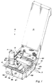
- a filter apparatus for filtering machine tool coolant which does not form part of the present invention is generally indicated by reference numeral 10.
- apparatus 10 includes a filter assembly 12 which is easier to keep clean and that prevents machining chips, particulate as well as elongate contaminants in the coolant from being recirculated to the machine tools.
- a settling tank 14 is set into a pit disposed below the floor level or elevation F in an industrial environment.
- Tank 14 is generally rectilinear in configuration and has a sloping end wall or ramp 16 for use in conjunction with a dragout conveyor 18.
- Tank 14 is comprised of two discrete compartments; a dirty or contaminated coolant compartment, designated 20, for receiving dirty coolant from trough T in communication with the machine tools, also not shown; and a clean coolant compartment 22 for receiving clean filtered coolant from tank 14.
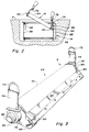
- drum filter 24 Within dirty coolant compartment 20, there is provided a horizontally disposed drum filter assembly 24 between two parallel sides 26,28 of tank 14 for filtering the dirty coolant whereby clean coolant filtrate may be supplied machine tools as explained hereinafter.
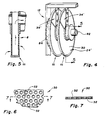
- drum filter 24 as best seen in Fig. 3, has a foraminous surface 30 comprised of a non-reticulated metal screen having minute openings 32, as best seen in Figs. 6 and 7, and a smooth planar surface. Minute openings 32 are preferably in the range of between 50 and 250 micrometres in diameter and most preferably 120 micrometres. As shown in Figs. 6 and 7, minute openings 32 in the direction of coolant movement are hourglass in shape.
- drum filter 24 collects a filter cake composed of machining chips (particulate including elongate contaminants) from machine cool operations about its surface 30. Coolant is moved through the filter cake and surface 30 of the drum filter 24 into the interior of the drum. More particularly, a suction is drawn on the inside of drum 24 by pump P. Coolant in dirty filter tank compartment 20 thus passes through the filter cake and drum, and cleaned or filtered coolant is supplied by the pump P to the machine tools.
- Dragout conveyor 18 is conventional in construction and serves to remove both the solids settled out from the coolant and the filter cake removed from the filter drum 24 by a doctor blade 34 shown in Figure 3, both of which settle to the bottom of tank compartment 20.
- Doctor blade 34 comprises a non-abrasive material, preferably a flexible plastic material, having a leading edge flexed to contact the surface 30 in a parallel relationship whereby the surface is easily cleaned.
- the solids removed from the bottom of the tank compartment 20 by conveyor 18 are deposited in a suitable receptacle, not shown, at the end of the conveyor.
- Clean coolant compartment 22 includes an elevated or false floor 36 above the lower tank wall bottom and which defines a lower chamber 38 for receiving clean coolant from the suction side of filter drum via conduit 40.
- a main outlet conduit 42 Disposed in clean compartment 22 is a main outlet conduit 42 for connection with the machine tools.
- clean coolant is supplied the machine tools from the suction side of filter 24 by way of chamber 38, pump P and outlet conduit 42.
- the purpose of clean coolant compartment 22 is to provide a reservoir of clean coolant which can be supplied the machine tools when the drum filter 24 is indexed for cleaning.
- a valve not shown, is opened affording communication between the clean coolant in chamber 38 and the clean coolant in the remainder of clean coolant compartment 22 above floor 36.
- pump P suction is applied to the clean coolant in compartment 22 to supply coolant to the machine tools.
- the suction is also removed with respect to the inside of the drum filter assembly 24 to facilitate cleaning filter cake from the outside surface of the drum. Upon closing this valve, pump suction to the filter drum is reestablished, as will become clear from the ensuing description.
- drum filter 24 is shown to have axial extensions at each end, one end comprising a ball duct joint 50, the socket 52 of which is placed in an aperture 54 in the side wall 28 of tank 12; and the other end of which filter 24 is provided with a spring axially outwardly pressed cap or pin 56 which in the position shown has an over-all length greater than the distance between the wall 26 and the base of the socket 52 as shown.
- the filter assembly 24 when the filter assembly 24 has its ball duct end 50 placed into the socket 52 guided by the U-shaped bracket 58, the other end may have its pin 56 pressed against the wall 26 of the tank 12 so that a resilient means, which may be a compression spring inside an axially aligned sleeve in the drum filter 24, will urge the whole assembly 24 and its ball duct 50 into sealing engagement with the socket 52 anchored in the opposite parallel wall 28 of the tank 12. Since it is not possible to lift the ball duct 50 vertically out of its socket 52 in order to remove the drum filter assembly 24, the opposite end with pin 56 must be lifted first as shown in Figure 2 so that ample space above the tank 12 is had to remove the ball duct 50 from socket duct 52.
- a resilient means which may be a compression spring inside an axially aligned sleeve in the drum filter 24
- the ends of the drum filter assembly 24 may be provided with lifting handles 72 as shown in Figures 2 and 3, in which event it is necessary that the connections 74 between each handle 72 and the non-rotatable bearing ends 76 and 76' should be inwardly directed or flexible plates to permit clearance from the side walls 24 and 26 as shown particularly at the right end of the filter 24.
- the filter assembly 12 is a drum filter assembly 24 having foraminous non-reticulated metal screen surface 30 providing the filtering.
- An end disc 80 is centrally apertured and may be integral through a hollow hub portion 82 with the ball duct 50.
- Another end disc 84 is also communicable with hollow hub portion 82 and may be peripherally serrated to form a ratchet wheel engageable by a drive means, not shown, for rotating the filter assembly 12 for cleaning.
- Filter assembly 24' is a disc filter assembly comprising a plurality of hollow disk filter elements 88 spaced along and in communication with hub portion 82 which can, in number, increase the filter surface area as compared to a drum filter of the same volume.
- Each disk filter element 88 includes the same foraminous surface 30 and an adapted doctor blade 34' for scraping the surface.
- coolant is communicated through surface 30 of disk filter 88, whereby machining chips, particulate as well as elongated contaminants form a filter cake on the surface, and is passed through the hollow disc and into hub 82.
- the stationary bearing means 76 and 76' are provided with radially outwardly extending flanged wing portions 94 for adjustably supporting the flexible plastic scraping or doctor blades 34,34' against the outer filter surface 30.
- the non-abrasive doctor blades 34,34' remove the fine solid particles that accumulate and form a filter cake on the foraminous non-reticulated surface 30 when the filter 24,24' is indexed at intervals by the drive means.
- the suction in duct 92 is reduced to aid in allowing the removed particles to settle and be carried out by flights 96 of the conveyor.
Landscapes
- Chemical & Material Sciences (AREA)
- Chemical Kinetics & Catalysis (AREA)
- Auxiliary Devices For Machine Tools (AREA)
- Liquid Crystal (AREA)
- Polarising Elements (AREA)
- Filtering Materials (AREA)
Claims (7)
- Tauchfiltervorrichtung für Werkzeugmaschinenkühlmittel, das in einem Absetzbehälter aufgefangen wird, wobei die Filtervorrichtung folgendes umfaßt:
ein Hohlnabenteil (82) mit einer Längsachse, durch die Werkzeugmaschinenkühlmittel fließt;
eine Mehrzahl von Hohlscheiben-Filtereinsätzen (88), die um die genannte Achse rotieren und entlang und in Verbindung mit dem Hohlraum des genannten Nabenteils (82) voneinander beabstandet positioniert sind und auf einer Oberfläche Schmutzstoffe von dem Werkzeugmaschinenkühlmittel auffangen, das in Bewegungsrichtung von der Außenseite jedes genannten Filtereinsatzes in den Hohlraum von dessen Nabenteils fließt; und
einen Schaber (34') zum Abschaben jeder perforierten Oberfläche zum Entfernen aufgefangener Schmutzstoffe von der Oberfläche jedes der genannten Filtereinsätze;
dadurch gekennzeichnet, daß jeder Hohlscheiben-Filtereinsatz (88) eine perforierte Oberfläche (30) aufweist, die ein nicht netzförmig angelegtes Drahtsieb mit winzigen Öffnungen (32) und einer glatten, ebenen Oberfläche umfaßt, wobei die Öffnungen in Bewegungsrichtung sanduhrförmig sind. - Vorrichtung nach Anspruch 1, worin die genannten Öffnungen (32) eine Größe von 50 bis 250 Mikron haben.
- Vorrichtung nach Anspruch 2, worin die genannten Öffnungen (32) eine Größe von allgemein 120 Mikrometer haben.
- Filtervorrichtung nach einem der Ansprüche 1 bis 3, wobei der genannte Schaber (34') aus flexiblen Kunststoffschaufeln besteht.
- Filtervorrichtung nach Anspruch 4, wobei die genannten Schaufeln eine Vorderkante aufweisen, die in einer allgemein parallelen Beziehung auf die Filteroberfläche (30) auftrifft.
- Filtervorrichtung nach einem der Ansprüche 1 bis 5, weiterhin umfassend ein Mittel für die Beförderung des Werkzeugmaschinenkühlmittels von der Außenseite jedes Einsatzes in dessen Hohlraum und anschließend durch die genannte Nabe.
- Verfahren zum Filtern von Schmutzstoffen aus Werkzeugmaschinenkühlmittel, umfassend die folgenden Schritte:
Einbringen eines Hohlscheiben-Filtereinsatzes (88) mit einem Hohlnabenteil (82), das um eine Längsachse rotiert, in verschmutztes Werkzeugmaschinenkühlmittel;
Ziehen des Werkzeugmaschinenkühlmittels von der Außenseite des Filtereinsatzes (88) in das Hohlnabenteil (82);
Auffangen von Schmutzstoffen aus dem Werkzeugmaschinenkühlmittel auf einer Oberfläche (30);
Rotieren des Filtereinsatzes (88); und
Abschaben der Oberfläche des Filtereinsatzes zum Entfernen gesammelter Schmutzstoffe von der Oberfläche,
dadurch gekennzeichnet, daß der Hohlscheiben-Filtereinsatz (88) eine perforierte Oberfäche (30) aufweist, die ein nicht netzförmig angelegtes Drahtsieb mit einer glatten, ebenen Oberfläche und winzigen, sanduhrförmigen Öffnungen (32) in der Oberfläche umfaßt.
Applications Claiming Priority (3)
| Application Number | Priority Date | Filing Date | Title |
|---|---|---|---|
| US575338 | 1990-08-30 | ||
| US07/575,338 US5158691A (en) | 1990-08-30 | 1990-08-30 | Filter apparatus and method for filtering contaminants from machine tool coolant |
| PCT/US1991/003809 WO1992004095A1 (en) | 1990-08-30 | 1991-05-30 | Filter apparatus for machine tool coolant |
Publications (3)
| Publication Number | Publication Date |
|---|---|
| EP0545934A1 EP0545934A1 (de) | 1993-06-16 |
| EP0545934A4 EP0545934A4 (en) | 1993-07-21 |
| EP0545934B1 true EP0545934B1 (de) | 1996-04-24 |
Family
ID=24299911
Family Applications (1)
| Application Number | Title | Priority Date | Filing Date |
|---|---|---|---|
| EP91910926A Expired - Lifetime EP0545934B1 (de) | 1990-08-30 | 1991-05-30 | Filtervorrichtung für werkzeugmaschinenkühlflüssigkeiten |
Country Status (7)
| Country | Link |
|---|---|
| US (1) | US5158691A (de) |
| EP (1) | EP0545934B1 (de) |
| JP (1) | JPH05509031A (de) |
| AT (1) | ATE137132T1 (de) |
| CA (1) | CA2090222C (de) |
| DE (1) | DE69119077T2 (de) |
| WO (1) | WO1992004095A1 (de) |
Families Citing this family (12)
| Publication number | Priority date | Publication date | Assignee | Title |
|---|---|---|---|---|
| FI86963C (fi) * | 1989-07-06 | 1992-11-10 | Ahlstroem Oy | Anordning och foerfarande foer behandling av massa |
| US5618424A (en) * | 1995-04-21 | 1997-04-08 | Nagaoka International Corp. | Rotary drum type device for separating solid particles from a liquid |
| DE29519626U1 (de) * | 1995-12-11 | 1996-01-25 | Deckel Maho GmbH, 87459 Pfronten | Reinigungsvorrichtung |
| US6571959B1 (en) * | 1999-09-22 | 2003-06-03 | Robin C. Moore | Coolant fluid cleaning method and apparatus |
| DE102004032334B3 (de) * | 2004-07-02 | 2005-10-20 | Mayfran Int Bv | Vorrichtung zur Aufnahme und Trennung von an Werkzeugmaschinen anfallenden Spänen und Kühlflüssigkeit (Transport) |
| EP1616621B1 (de) * | 2004-07-14 | 2011-05-11 | Grundfos A/S | Vorrichtung zur Fluidbehandlung |
| US7638061B2 (en) * | 2004-09-03 | 2009-12-29 | Hennig Incorporated | Coolant fluid cleaning method, system, and apparatus |
| JP5281321B2 (ja) * | 2008-06-12 | 2013-09-04 | 株式会社ノリタケカンパニーリミテド | 濾過用フィルターエレメント |
| US20100320158A1 (en) * | 2009-06-19 | 2010-12-23 | Brian Mahas | Separator separating chips and other material from coolant and method |
| ES2927357T3 (es) * | 2016-08-12 | 2022-11-04 | Evoqua Water Tech Llc | Filtro de disco de medios dobles prepantallla de filtro de disco |
| US12220657B2 (en) * | 2021-04-30 | 2025-02-11 | Pall Corporation | Filter disk segments |
| CN114470927A (zh) * | 2022-02-23 | 2022-05-13 | 北京首创环境科技有限公司 | 一种环片式自清洁过滤器及使用方法 |
Family Cites Families (20)
| Publication number | Priority date | Publication date | Assignee | Title |
|---|---|---|---|---|
| US1540325A (en) * | 1919-05-05 | 1925-06-02 | Harrington And King Perforatin | Perforated sheet |
| US1686017A (en) * | 1924-07-28 | 1928-10-02 | Michael V Lovett | Rendering apparatus |
| US2165931A (en) * | 1938-01-31 | 1939-07-11 | Le Val Filter Company Inc | Hollow disk filter aid retaining medium |
| US3096278A (en) * | 1959-03-09 | 1963-07-02 | Eimco Corp | Scraper assembly for filters |
| US3080064A (en) * | 1959-08-14 | 1963-03-05 | Ametek Inc | Filter scraper |
| US3283906A (en) * | 1963-12-19 | 1966-11-08 | Cleveland Electric Illuminatin | Vacuum filter |
| US3643806A (en) * | 1969-03-24 | 1972-02-22 | United States Filter Corp | Adjustable knife blade for dry filter cake discharge |
| FR2068082A6 (de) * | 1969-11-27 | 1971-08-20 | Guinard Pompes | |
| US4003837A (en) * | 1973-05-29 | 1977-01-18 | Osborne Winston G | Self-cleaning strainer |
| US4083787A (en) * | 1976-08-19 | 1978-04-11 | Alar Engineering Corporation | Rotary vacuum filter |
| US4131549A (en) * | 1977-05-16 | 1978-12-26 | Ferrara Louis T | Serum separation device |
| US4131548A (en) * | 1977-10-31 | 1978-12-26 | Peterson Filters Corporation | Rotary disc filter scraper apparatus |
| GB8301099D0 (en) * | 1983-01-15 | 1983-02-16 | Aspley Metals Ltd | Moulding of elastomeric material components |
| JPS60178027A (ja) * | 1984-02-24 | 1985-09-12 | Kubota Ltd | 樹脂管製造用芯金装置 |
| JPS61268317A (ja) * | 1985-05-23 | 1986-11-27 | Toyo Roki Seizo Kk | 濾過材 |
| US4836917A (en) * | 1986-10-06 | 1989-06-06 | Kanebo, Ltd. | Apparatus for performing separation of a solid-liquid mixture |
| FI76705C (fi) * | 1987-04-16 | 1988-12-12 | Valmet Paper Machinery Inc | Foerfarande foer rengoering av filterplattor foer sugtorkanordning. |
| JPH01215318A (ja) * | 1988-02-20 | 1989-08-29 | Akua Runesansu Gijutsu Kenkyu Kumiai | 濾過装置 |
| US4932112A (en) * | 1988-10-06 | 1990-06-12 | Tim Tikkanen | Sieve plate and process for making it |
| US4957630A (en) * | 1988-12-27 | 1990-09-18 | Bratten Jack R | Drum filter with divergent hole perforated filter media |
-
1990
- 1990-08-30 US US07/575,338 patent/US5158691A/en not_active Expired - Fee Related
-
1991
- 1991-05-30 WO PCT/US1991/003809 patent/WO1992004095A1/en not_active Ceased
- 1991-05-30 DE DE69119077T patent/DE69119077T2/de not_active Expired - Fee Related
- 1991-05-30 AT AT91910926T patent/ATE137132T1/de not_active IP Right Cessation
- 1991-05-30 JP JP3510858A patent/JPH05509031A/ja active Pending
- 1991-05-30 EP EP91910926A patent/EP0545934B1/de not_active Expired - Lifetime
- 1991-05-30 CA CA002090222A patent/CA2090222C/en not_active Expired - Fee Related
Also Published As
| Publication number | Publication date |
|---|---|
| JPH05509031A (ja) | 1993-12-16 |
| DE69119077T2 (de) | 1996-08-22 |
| EP0545934A1 (de) | 1993-06-16 |
| CA2090222C (en) | 1997-02-04 |
| ATE137132T1 (de) | 1996-05-15 |
| EP0545934A4 (en) | 1993-07-21 |
| WO1992004095A1 (en) | 1992-03-19 |
| DE69119077D1 (de) | 1996-05-30 |
| US5158691A (en) | 1992-10-27 |
Similar Documents
| Publication | Publication Date | Title |
|---|---|---|
| US5389256A (en) | Filter apparatus for machine tool coolant | |
| EP0545934B1 (de) | Filtervorrichtung für werkzeugmaschinenkühlflüssigkeiten | |
| US6355167B1 (en) | Apparatus for filtering contaminated liquids | |
| EP0253367A2 (de) | Trommelfiltereinrichtung | |
| EP0312354B1 (de) | Schlammfilter | |
| EP1098690B1 (de) | Verfahren und vorrichtung zur filtration von partikeln aus einer flüssigkeit | |
| US4421645A (en) | Compact universal drum filter settler | |
| WO2001021281A1 (en) | Coolant fluid cleaning method and apparatus | |
| US20030010723A1 (en) | Media vacuum filter | |
| USRE32135E (en) | Compact universal drum filter settler | |
| US20020139722A1 (en) | Industrial filter with arrangement for removing machining chips from coolant prior to filtering | |
| JP2007098538A (ja) | 個液分離システム | |
| EP0225017B1 (de) | Filterapparat | |
| JP2751091B2 (ja) | 切削液の濾過装置 | |
| US4277339A (en) | Paint pigment skimmer | |
| US5505861A (en) | System for gravity settling of fine particles from a liquid | |
| JPH0326891Y2 (de) | ||
| JP4794267B2 (ja) | 沈殿分離装置 | |
| JPH0129005Y2 (de) | ||
| US2816662A (en) | Oil cleaning device | |
| JPH0433929Y2 (de) | ||
| RU2116114C1 (ru) | Устройство для очистки жидкостей | |
| CN110073987B (zh) | 一种通过抽拉达到振幅效果的清理用猫砂盆 | |
| KR200166565Y1 (ko) | 자동차 세척용 회전브러시의 세척장치 | |
| JPH0957570A (ja) | 工作機械用液処理装置 |
Legal Events
| Date | Code | Title | Description |
|---|---|---|---|
| PUAI | Public reference made under article 153(3) epc to a published international application that has entered the european phase |
Free format text: ORIGINAL CODE: 0009012 |
|
| 17P | Request for examination filed |
Effective date: 19930224 |
|
| AK | Designated contracting states |
Kind code of ref document: A1 Designated state(s): AT BE CH DE DK ES FR GB GR IT LI LU NL SE |
|
| A4 | Supplementary search report drawn up and despatched |
Effective date: 19930604 |
|
| AK | Designated contracting states |
Kind code of ref document: A4 Designated state(s): AT BE CH DE DK ES FR GB GR IT LI LU NL SE |
|
| 17Q | First examination report despatched |
Effective date: 19940209 |
|
| GRAH | Despatch of communication of intention to grant a patent |
Free format text: ORIGINAL CODE: EPIDOS IGRA |
|
| GRAA | (expected) grant |
Free format text: ORIGINAL CODE: 0009210 |
|
| AK | Designated contracting states |
Kind code of ref document: B1 Designated state(s): AT BE CH DE DK ES FR GB GR IT LI LU NL SE |
|
| PG25 | Lapsed in a contracting state [announced via postgrant information from national office to epo] |
Ref country code: NL Free format text: LAPSE BECAUSE OF FAILURE TO SUBMIT A TRANSLATION OF THE DESCRIPTION OR TO PAY THE FEE WITHIN THE PRESCRIBED TIME-LIMIT Effective date: 19960424 Ref country code: LI Free format text: LAPSE BECAUSE OF FAILURE TO SUBMIT A TRANSLATION OF THE DESCRIPTION OR TO PAY THE FEE WITHIN THE PRESCRIBED TIME-LIMIT Effective date: 19960424 Ref country code: GR Free format text: LAPSE BECAUSE OF FAILURE TO SUBMIT A TRANSLATION OF THE DESCRIPTION OR TO PAY THE FEE WITHIN THE PRESCRIBED TIME-LIMIT Effective date: 19960424 Ref country code: FR Effective date: 19960424 Ref country code: ES Free format text: THE PATENT HAS BEEN ANNULLED BY A DECISION OF A NATIONAL AUTHORITY Effective date: 19960424 Ref country code: DK Effective date: 19960424 Ref country code: CH Free format text: LAPSE BECAUSE OF FAILURE TO SUBMIT A TRANSLATION OF THE DESCRIPTION OR TO PAY THE FEE WITHIN THE PRESCRIBED TIME-LIMIT Effective date: 19960424 Ref country code: BE Effective date: 19960424 Ref country code: AT Effective date: 19960424 |
|
| REF | Corresponds to: |
Ref document number: 137132 Country of ref document: AT Date of ref document: 19960515 Kind code of ref document: T |
|
| REF | Corresponds to: |
Ref document number: 69119077 Country of ref document: DE Date of ref document: 19960530 |
|
| PG25 | Lapsed in a contracting state [announced via postgrant information from national office to epo] |
Ref country code: LU Free format text: LAPSE BECAUSE OF NON-PAYMENT OF DUE FEES Effective date: 19960531 |
|
| ITF | It: translation for a ep patent filed | ||
| PG25 | Lapsed in a contracting state [announced via postgrant information from national office to epo] |
Ref country code: SE Effective date: 19960724 |
|
| EN | Fr: translation not filed | ||
| NLV1 | Nl: lapsed or annulled due to failure to fulfill the requirements of art. 29p and 29m of the patents act | ||
| REG | Reference to a national code |
Ref country code: CH Ref legal event code: PL |
|
| PLBE | No opposition filed within time limit |
Free format text: ORIGINAL CODE: 0009261 |
|
| STAA | Information on the status of an ep patent application or granted ep patent |
Free format text: STATUS: NO OPPOSITION FILED WITHIN TIME LIMIT |
|
| 26N | No opposition filed | ||
| PGFP | Annual fee paid to national office [announced via postgrant information from national office to epo] |
Ref country code: GB Payment date: 20000524 Year of fee payment: 10 |
|
| PGFP | Annual fee paid to national office [announced via postgrant information from national office to epo] |
Ref country code: DE Payment date: 20000529 Year of fee payment: 10 |
|
| PG25 | Lapsed in a contracting state [announced via postgrant information from national office to epo] |
Ref country code: GB Free format text: LAPSE BECAUSE OF NON-PAYMENT OF DUE FEES Effective date: 20010530 |
|
| GBPC | Gb: european patent ceased through non-payment of renewal fee |
Effective date: 20010530 |
|
| PG25 | Lapsed in a contracting state [announced via postgrant information from national office to epo] |
Ref country code: DE Free format text: LAPSE BECAUSE OF NON-PAYMENT OF DUE FEES Effective date: 20020301 |
|
| PG25 | Lapsed in a contracting state [announced via postgrant information from national office to epo] |
Ref country code: IT Free format text: LAPSE BECAUSE OF NON-PAYMENT OF DUE FEES;WARNING: LAPSES OF ITALIAN PATENTS WITH EFFECTIVE DATE BEFORE 2007 MAY HAVE OCCURRED AT ANY TIME BEFORE 2007. THE CORRECT EFFECTIVE DATE MAY BE DIFFERENT FROM THE ONE RECORDED. Effective date: 20050530 |