EP0545936B1 - Anordnung mit doppel-mittelpunkt zur sicherstellung einer geschützten ringverbindung - Google Patents
Anordnung mit doppel-mittelpunkt zur sicherstellung einer geschützten ringverbindung Download PDFInfo
- Publication number
- EP0545936B1 EP0545936B1 EP91911538A EP91911538A EP0545936B1 EP 0545936 B1 EP0545936 B1 EP 0545936B1 EP 91911538 A EP91911538 A EP 91911538A EP 91911538 A EP91911538 A EP 91911538A EP 0545936 B1 EP0545936 B1 EP 0545936B1
- Authority
- EP
- European Patent Office
- Prior art keywords
- ring
- hybrid
- unidirectional
- node
- hybrid ring
- Prior art date
- Legal status (The legal status is an assumption and is not a legal conclusion. Google has not performed a legal analysis and makes no representation as to the accuracy of the status listed.)
- Expired - Lifetime
Links
Images


Classifications
-
- H—ELECTRICITY
- H04—ELECTRIC COMMUNICATION TECHNIQUE
- H04L—TRANSMISSION OF DIGITAL INFORMATION, e.g. TELEGRAPHIC COMMUNICATION
- H04L12/00—Data switching networks
- H04L12/28—Data switching networks characterised by path configuration, e.g. LAN [Local Area Networks] or WAN [Wide Area Networks]
- H04L12/42—Loop networks
- H04L12/437—Ring fault isolation or reconfiguration
Definitions
- the invention relates generally to a communications network and, more specifically, to the interconnection of self-healing ring networks.
- a ring communications network is made up of nodes that are connected in tandem by a unidirectional communications path. Each node receives transmissions from the adjacent upstream node, and if the communication is destined for a downstream node, the communication is re-transmitted to the adjacent downstream node. Otherwise, each node transmits its own communications to the adjacent downstream node.
- a drawback of such a network is that a break in the ring would prevent any node upstream of the break from communicating with any node downstream of the break. Similarly, the complete failure of a node would have the same effect as a break in the ring.
- Lau a subrate multiplexed signal is utilized for ring communications.
- Each node has the capability of demultiplexing the main signal into its constituent subrates (channels), and channels destined for that node (local channels) are sent to receiving equipment within the node, while channels destined for downstream nodes (through channels) are multiplexed with originating local channels, and the resultant high level signal is transmitted to the adjacent downstream node.
- This process is simultaneously performed using identical equipment in the node for a second ring transmitting in the opposite direction.
- each node detects a fault in an incoming line, an error signal is placed on all of the channels following the demultiplexing.
- the receiving equipment in each node includes a selector which monitors the communications arriving on each local channel from both rings. If an error signal is detected on a local channel, the selector selects the communication from the associated channel of the other ring to send to the receiver.
- the arrangement of Lau ceases functioning as a ring if the ring is broken. However, communications among the nodes is maintained following such a break. For this reason, the arrangement of Lau has been called a hybrid ring, since it normally operates as a ring, but then it does not operate as a ring following a break in the ring or the loss of a node.
- an arrangement for interconnecting two autonomous but interrelated rings is disclosed.
- simultaneous breaks in both rings can be compensated without loss of communications between any two nodes.
- the arrangement employs a master node from each ring and two unidirectional paths connected between the master nodes to couple the two rings. Even though the rings are protected from breaks in each ring, an outage in either master node or a unidirectional path breaks the communication path from one interrelated ring to the other.
- a pair of serving nodes are interposed in each of two independent hybrid rings.
- the first serving node couples both unidirectional paths of the first hybrid to the first unidirectional path of the second hybrid, whereas the second serving node couples both unidirectional paths of the first hybrid to the second unidirectional path of the second hybrid.
- the first serving node couples both unidirectional paths of the second hybrid to the second unidirectional path of the first hybrid, whereas the second serving node couples both unidirectional paths of the second hybrid to the first unidirectional path of the first hybrid.
- a property of the present invention is that the pair of serving nodes provide a protected interconnection between multiple survivable ring networks. Any traffic (i.e., channels) that passes between rings is fully and automatically protected against the loss of a serving node, where a serving node provides paths between rings. For survivability of traffic, protection against the loss of a serving node is essential in addition to having protection against a break in the ring.
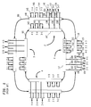
- node 1 comprises controllers 117 and 118 and selectors 119-121. Controller 117 is connected with ring 101, which carries signals in a clockwise direction, and controller 118 is connected with ring 100, which carries signals in a counterclockwise direction.
- the signals on each ring comprise six subrate channels, each of which is dedicated to communications between a pre-selected pair of basically identical nodes.
- Each node feeds three subrate receivers (not shown), which in the case of node 1 have lines 104, 107 and 110, respectively, as input.
- the channel carrying communications between nodes 2 and 1 would be extracted from ring 101 by controller 117 (by demultiplexing the signal on ring 101), and sent to selector 119 over line 102. Controller 118 would extract the associated channel off ring 100 and send it to selector 119 over line 103. Selector 119 would select one of the signals arriving on lines 102 and 103, based on the presence or absence of an error signal on either line. The selected signal would be sent to the receiver over line 104.
- a transmitter (not shown) would transmit two identical signals destined for node 2, one to controller 117 and one to controller 118, for reinsertion into the respective loops.
- Controllers 117 and 118 then multiplex the three channels originating from node 1 with the three through channels, and transmit the resultant higher level signals on their associated loops (loop 101 toward node 4 and loop 100 toward node 2). In this way, each node has two redundant communications paths to each of the other nodes, both paths being continuously active.
- FIG. 2 depicts the manner of interconnecting two interrelated nodes in the master-master relationship as disclosed by Lau; the two master rings are denoted by reference numerals 10 and 20, respectively.
- Each ring has an interposed master node shown as nodes 30 and 31, respectively.
- each node includes an arrangement of two controllers 11 and 12 and a selector 13; these components are basically the same as controllers 117 and 118 and selector bank 119-121 in node 1 of Lau.
- Nodes 30 and 31 are interconnected by unidirectional communication paths 33 and 34.
- node 30 the arrangement in FIG. 2 of node 30 is referred to below as an ADM (Add-Drop Multiplexer) node, whereas the arrangement of controllers 11 and 12, selector 13, input links 14 and 15, and output link 34 is referred to as a DM (Drop Multiplexer) node.
- ADM Address-Drop Multiplexer
- FIG. 3 depicts the manner in which two hybrid rings can be interconnected in a dual-hubbed arrangement to provide protection against node failures.
- FIG. 3 depicts the manner in which two hybrid rings can be interconnected in a dual-hubbed arrangement to provide protection against node failures.
- channels 303 destined for access ring 301 are added onto interoffice ring 302 by multiplexing them with "through" channels on ring 302, thus creating a channelized high level signal on ring 302.
- Ring 301 comprises two unidirectional communication paths 317 and 318 transmitting in opposing directions, and similarly ring 302 comprises two unidirectional paths 311 and 312.
- ring 302 operates at a higher level than ring 301 in a given hierarchical network.
- ADM 310 transmits these newly added channels in both the clockwise (CW) and counterclockwise (CCW) directions on ring 302 on paths 311 and 312, respectively.
- These newly added channels from node 310 travel through adjacent nodes 320 and 350 to the designated serving nodes, i.e., primary node 340 and secondary node 330, which distribute channels on ring 302 to various customer terminations 304-307 on ring 301.
- Channel assignments onto ring 301 are made at serving nodes 330 and 340.
- Channels from node 310 are routed to both primary and secondary serving nodes 340 and 330 via a so-called "drop-and-continue" property.
- the drop-and-continue property permits the same traffic to be delivered to the two serving nodes from the same direction. For instance, CCW traffic on path 312 is dropped off at DM 341 and passed to DM 331. Likewise, CW traffic on path 311 is dropped off at DM 331 and passed to DM 341.
- the continued signal is forwarded like a pass-through signal; in this way both primary 340 and secondary node 330 can select from equivalent signals.
- selectors 342 and 332 in the primary and secondary serving nodes 340 and 330, respectively are set up such that the preferred (or default) signal for traffic selection are opposite of each other, assuring that a break in ring 302 will not cause channel switching in both the serving nodes.
- selector 342 in DM 341 selects either the CW or CCW channel received from node 310, and this signal serves as the input to DM 360 via link 343.
- DM 360 transmits this signal in only the CCW direction, namely, path 318 on ring 301. This implies that a selector is needed only for each channel received from ADM node 310.
- traffic from customer terminations 304-307 on ring 301 is routed through ADM's 380 and 390 to both primary and secondary nodes 340 and 330 via the drop-and-continue property.
- Channel assignments onto ring 302 are made at serving nodes 340 and 330. Selected traffic out of primary and secondary nodes 340 and 330 is transmitted in only one direction on ring 302, opposite to each other, thus satisfying the hybrid ring requirement of having equivalent signals in the CW and CCW directions on interoffice ring 302.
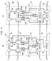
- the block diagram of FIG. 4 is illustrative of the routing of channel signals between interoffice ring 302 and access ring 301.
- DM 341 is shown to comprise controllers 345 and 346 as well as selector bank 342, which has been partitioned into two individual selectors 3421 and 3422.
- Selector 3421 is presently assigned to route signals to termination 304 (designated by "304" in selector 3421), and selector 3422 is assigned routing of signals for termination 307 ("307").
- Both controllers 345 and 346 feed channel signals to selector 342 and the appropriate channel is then routed to the assigned individual selectors 3421 or 3422.
- the output of selector 3421 is propagated over link 343 to DM 360.
- link 343 connects to controller 365 in DM 360; this controller couples to the CCW path of hybrid ring 301. Similar comments also apply to the routing of the channel signal destined for termination 307.
- controllers 365 and 366 and selector 361 in DM 360 are considered as exemplary.
- the channel assigned to selector 361 is termination 308, which is dropped from ADM 310.
- Controllers 365 and 366 feed duplicate signals from the two unidirectional rings of ring 301 to selector 361. The output of this selector is propagated over link 363 to controller 345 in DM 341.
- DM 331 similarly comprises controller 335 and 336 and selector bank 332, including selectors 3321 and 3322.
- serving node 330 is arranged in complementary manner to serving node 340, that is, node pair DM 341 and DM 360 serve one of the unidirectional rings in each hybrid; similarly, node pair DM 331 and DM 370 serve the other of the unidirectional rings. Accordingly, the operation of primary and secondary nodes 340 and 330 is symmetrical. With this arrangement, service will continue between ring 301 and ring 302 in the event of loss of primary node 340 or secondary node 330, including interconnecting links represented by links 333, 343, and 363, and there is always a path between interoffice and access rings with the loss of either node.
- both rings 301 and 302 are treated as autonomous, independent rings which makes for a robust network. For example, when there is a break in either ring, the operation in the other ring is not affected (i.e., there is no need to initiate fault recovery via channel switching). Any fault recovery is confined to the ring with the fault. This means that ring 302 can operate at a different channel selector level than ring 301 and vice versa. More notably, this configuration can survive.a simultaneous break in both the ring 301 and ring 302 networks without loss of communications between rings 301 and 302.
Landscapes
- Engineering & Computer Science (AREA)
- Computer Networks & Wireless Communication (AREA)
- Signal Processing (AREA)
- Small-Scale Networks (AREA)
- Electron Beam Exposure (AREA)
Claims (3)
- Schaltung zum Verbinden eines ersten Hybridring-Netzwerks (301) mit einem zweiten Hybridring-Netzwerk (302), wobei jeder Ring einen ersten und einen zweiten unidirektionalen Pfad enthält, wobei die Schaltung dadurch gekennzeichnet ist, daß sie folgendes aufweist:einen ersten autonomen Serverknoten (340), der mit den Hybridringen gekoppelt ist, zum Koppeln der unidirektionalen Pfade des ersten Hybridrings mit nur dem ersten unidirektionalen Pfad des zweiten Hybridrings, und zum Koppeln der unidirektionalen Pfade des zweiten Hybridrings mit nur dem zweiten unidirektionalen Pfad des ersten Hybridrings, undeinen zweiten autonomen Serverknoten (330), der mit den Hybridringen gekoppelt ist, zum Koppeln der unidirektionalen Pfade des ersten Hybridrings mit nur dem zweiten unidirektionalen Pfad des zweiten Hybridrings, und zum Koppeln der unidirektionalen Pfade des zweiten Hybridrings mit nur dem ersten unidirektionalen Pfad des ersten Hybridrings.
- Schaltung zum Verbinden eines ersten Hybridrings (301) mit einem zweiten Hybridring (302), wobei jeder Ring Signale auf Kanälen ausbreitet und jeder Ring erste und zweite unidirektionale Pfade enthält, dadurch gekennzeichnet, daß sie folgendes aufweist:einen ersten Serverknoten (340), der folgendes enthält:einen ersten Abzweig-Multiplexer DM (341), der im ersten Hybridring angeordnet ist, und einen zweiten Abzweig-Multiplexer DM (360), der im zweiten Hybridring angeordnet ist, wobei jeder Multiplexer folgendes enthält:eine erste und eine zweite Steuerung, wobei die erste Steuerung (345, 365) mit dem ersten unidirektionalen Pfad gekoppelt ist und die zweite Steuerung (346, 366) mit dem zweiten unidirektionalen Pfad des zugehörigen Hybridrings gekoppelt ist, undeinen Selektor (342, 361), der auf die erste und die zweite Steuerung antwortet, wobei der Selektor Selektorausgänge entsprechend den Kanälen hat, die sich zwischen den Hybridringen ausbreiten,eine erste unidirektionale Verbindung (343), die den Selektor im ersten DM mit der ersten Steuerung im zweiten DM verbindet, undeine zweite unidirektionale Verbindung (363), die den Selektor im zweiten DM mit der zweiten Steuerung im ersten DM verbindet, undeinen zweiten Serverknoten (330), der folgendes enthält:einen dritten Abzweig-Multiplexer (331), der im ersten Hybridring angeordnet ist, und einen vierten Abzweig-Multiplexer (370), der im zweiten Hybridring angeordnet ist, wobei der Multiplexer folgendes enthält:eine dritte und eine vierte Steuerung, wobei die dritte Steuerung (335) mit dem ersten unidirektionalen Pfad gekoppelt ist und die vierte Steuerung (336) mit dem zweiten unidirektionalen Pfad des zugehörigen Hybridrings gekoppelt ist, undeinen Selektor (332), der auf die dritte und die vierte Steuerung antwortet, wobei der Selektor Selektorausgänge entsprechend den Kanälen hat, die sich zwischen den Hybridringen ausbreiten,eine dritte unidirektionale Verbindung, die den Selektor im dritten DM mit der vierten Steuerung im vierten DM verbindet, undeine vierte unidirektionale Verbindung, die den Selektor im vierten DM mit der dritten Steuerung im dritten DM verbindet.
- Verfahren zum Übertragen multiplexter Signale zwischen einem ersten Hybridring-Netzwerk (301) und einem zweiten Hybridring-Netzwerk (302), wobei jeder Ring einen ersten und einen zweiten unidirektionalen Pfad enthält, die jeweils erste und zweite multiplexte Signale ausbreiten, wobei das Verfahren dadurch gekennzeichnet ist, daß es folgende Schritte aufweist:Übertragen eines ausgewählten der ersten oder zweiten multiplexten Signale des ersten Hybridrings durch einen ersten Serverknoten (340) zu nur dem ersten unidirektionalen Pfad des zweiten Hybridrings,Übertragen eines ausgewählten der ersten oder zweiten multiplexten Signale des zweiten Hybridrings durch einen zweiten Serverknoten (330) zu nur dem zweiten unidirektionalen Pfad des ersten Hybridrings,Übertragen eines ausgewählten der ersten oder zweiten multiplexten Signale des ersten Hybridrings durch einen zweiten Serverknoten zu nur dem zweiten unidirektionalen Pfad des zweiten Hybridrings, undÜbertragen eines ausgewählten der ersten oder zweiten multiplexten Signale des zweiten Hybridrings durch einen zweiten Serverknoten zu nur dem ersten unidirektionalen Pfad des ersten Hybridrings.
Applications Claiming Priority (3)
| Application Number | Priority Date | Filing Date | Title |
|---|---|---|---|
| US07/577,273 US5218604A (en) | 1990-08-31 | 1990-08-31 | Dual-hubbed arrangement to provide a protected ring interconnection |
| US577273 | 1990-08-31 | ||
| PCT/US1991/003156 WO1992004788A1 (en) | 1990-08-31 | 1991-05-07 | A dual-hubbed arrangement to provide a protected ring interconnection |
Publications (3)
| Publication Number | Publication Date |
|---|---|
| EP0545936A1 EP0545936A1 (de) | 1993-06-16 |
| EP0545936A4 EP0545936A4 (en) | 1994-08-24 |
| EP0545936B1 true EP0545936B1 (de) | 1999-09-08 |
Family
ID=24308011
Family Applications (1)
| Application Number | Title | Priority Date | Filing Date |
|---|---|---|---|
| EP91911538A Expired - Lifetime EP0545936B1 (de) | 1990-08-31 | 1991-05-07 | Anordnung mit doppel-mittelpunkt zur sicherstellung einer geschützten ringverbindung |
Country Status (6)
| Country | Link |
|---|---|
| US (1) | US5218604A (de) |
| EP (1) | EP0545936B1 (de) |
| JP (1) | JPH07112203B2 (de) |
| CA (1) | CA2090429C (de) |
| DE (1) | DE69131597T2 (de) |
| WO (1) | WO1992004788A1 (de) |
Families Citing this family (51)
| Publication number | Priority date | Publication date | Assignee | Title |
|---|---|---|---|---|
| US5384566A (en) * | 1991-10-15 | 1995-01-24 | Integrated Networks Corporation | Load sharing system for computer network protocols |
| JP2812834B2 (ja) * | 1992-03-18 | 1998-10-22 | 富士通株式会社 | 多重リング回線用ノード装置及びそのノード装置を用いた多重リング回線網 |
| US5440540A (en) * | 1992-03-26 | 1995-08-08 | Kremer; Wilhelm | Ring interworking between a bidirectional line-switched ring transmission system and another ring transmission system |
| US5442620A (en) * | 1992-03-26 | 1995-08-15 | At&T Corp. | Apparatus and method for preventing communications circuit misconnections in a bidirectional line-switched ring transmission system |
| US5341364A (en) * | 1992-06-02 | 1994-08-23 | At&T Bell Laboratories | Distributed switching in bidirectional multiplex section-switched ringtransmission systems |
| US5442623A (en) * | 1992-08-17 | 1995-08-15 | Bell Communications Research, Inc. | Passive protected self healing ring network |
| US5390164A (en) * | 1993-10-22 | 1995-02-14 | At&T Corp. | Ring interworking between bidirectional line-switched ring transmission systems |
| US5394389A (en) * | 1993-10-22 | 1995-02-28 | At&T Corp. | Ring interworking between bidirectional line-switched ring transmission systems and path-switched ring transmission systems |
| US5406549A (en) * | 1993-10-22 | 1995-04-11 | At&T Corp. | Ring interworking between path-switched ring transmission systems |
| US5742605A (en) * | 1994-02-28 | 1998-04-21 | Sprint Communications Co., L.P. | Synchronous optical network using a ring architecture |
| JPH07264223A (ja) * | 1994-03-18 | 1995-10-13 | Fujitsu Ltd | ネットワークの信号救済方法および装置 |
| JPH07264227A (ja) * | 1994-03-18 | 1995-10-13 | Fujitsu Ltd | 複合リング状ネットワーク制御方式 |
| SE515560C2 (sv) * | 1995-04-03 | 2001-08-27 | Ericsson Telefon Ab L M | Optiskt nät samt anordning och förfarande i detta |
| US5684789A (en) * | 1995-06-29 | 1997-11-04 | Lucent Technologies Inc. | Remote control, link independent A/B switch box with diagnostic loopback |
| US6076117A (en) * | 1995-11-13 | 2000-06-13 | Billings; Roger E. | Packet merging hub system for sequentially merging received data in a network hub into data packets before broadcasting to a plurality of destination computers |
| US6115747A (en) * | 1995-11-13 | 2000-09-05 | Roger E. Billings | Computer network interface that merges remote data received from other computers with local data before transmitting the merged data to a network |
| US6061730A (en) * | 1995-11-13 | 2000-05-09 | Billings; Roger E. | Methods and apparatus for communicating data in computer networks with separate packet assembly and packet broadcast channels |
| US5793981A (en) * | 1995-11-13 | 1998-08-11 | Billings; Roger E. | System for communicating data in a network using both a daisy chain link and separate broadcast links |
| US5761433A (en) * | 1995-11-13 | 1998-06-02 | Billings; Roger E. | System for communicating data in a network using both a daisy chain link and separate broadcast links |
| US7301953B1 (en) | 1996-10-22 | 2007-11-27 | Sprint Communications Company L.P. | Method and system for transporting a secondary communication signal with a primary communication signal |
| US7643500B1 (en) | 1996-10-22 | 2010-01-05 | Sprint Communications Company L.P. | Overhead replication for SONET signals |
| SE9702688D0 (sv) * | 1997-07-11 | 1997-07-11 | Ericsson Telefon Ab L M | A method and system for interconnicting ring networks |
| GB2332832B (en) * | 1997-12-23 | 2003-06-04 | Northern Telecom Ltd | Communication system and method of routing information therein |
| TW419917B (en) * | 1998-03-30 | 2001-01-21 | Toshiba Corp | Communication network system |
| US6147968A (en) * | 1998-10-13 | 2000-11-14 | Nortel Networks Corporation | Method and apparatus for data transmission in synchronous optical networks |
| US6639896B1 (en) | 1999-04-01 | 2003-10-28 | Diva Systems Corporation | Asynchronous serial interface (ASI) ring network for digital information distribution |
| US6826197B1 (en) | 1999-04-01 | 2004-11-30 | Sedna Patent Services, Llc | Data packet structure for digital information distribution |
| DE19922171B4 (de) * | 1999-05-12 | 2009-08-27 | Infineon Technologies Ag | Kommunikationssystem mit einem Kommunikationsbus |
| US6392990B1 (en) | 1999-07-23 | 2002-05-21 | Glenayre Electronics, Inc. | Method for implementing interface redundancy in a computer network |
| US6654341B1 (en) * | 1999-10-19 | 2003-11-25 | Ciena Corporation | Virtual line switching ring |
| US6959000B1 (en) | 2000-02-08 | 2005-10-25 | Lucent Technologies Inc. | Configuration management of a hybrid DCS-SONET ring network |
| DE10025283B4 (de) * | 2000-05-22 | 2005-12-08 | Fujitsu Siemens Computers Gmbh | Vorrichtung zur dynamischen Verbindung von mindestens zwei Datenringzellen |
| US7095714B2 (en) * | 2000-11-28 | 2006-08-22 | Kabushiki Kaisha Toshiba | Ring interconnection network system, node equipment, network management equipment, and path setting method |
| JP2002271354A (ja) * | 2001-03-06 | 2002-09-20 | Fujitsu Ltd | 光路切替装置及び、これを用いる光波長多重ダイバシティ通信システム |
| US20020141334A1 (en) * | 2001-03-28 | 2002-10-03 | Deboer Evert E. | Dynamic protection bandwidth allocation in BLSR networks |
| US7054264B2 (en) * | 2001-07-24 | 2006-05-30 | Corrigent Systems Ltd. | Interconnect and gateway protection in bidirectional ring networks |
| US7289428B2 (en) * | 2001-08-13 | 2007-10-30 | Tellabs Operations, Inc. | Inter-working mesh telecommunications networks |
| US7061859B2 (en) | 2001-08-30 | 2006-06-13 | Corrigent Systems Ltd. | Fast protection in ring topologies |
| EP1324543A1 (de) * | 2001-12-26 | 2003-07-02 | Alcatel | Verfahren zum Schutz von RPR Netzen mit erweiterter Topologie, insbesondere RPR Ring zu Ring und vermaschte Hauptnetze |
| DE60208150T2 (de) * | 2002-03-08 | 2006-06-22 | Alcatel | Verfahren zur Wiederherstellung nach Betriebstörungen in einem aus Ringen aufgebauten Kommunikationsnetz, ein zugehöriges Kommunikationsnetz und Netzelement |
| US6961306B2 (en) * | 2002-07-10 | 2005-11-01 | I/O Controls Corporation | Fiber optic control network and related method |
| US6965560B2 (en) | 2002-07-10 | 2005-11-15 | I/O Controls Corporation | Multi-tier, hierarchical fiber optic control network |
| US7046621B2 (en) | 2002-07-10 | 2006-05-16 | I/O Controls Corporation | Redundant multi-fiber optical ring network |
| CN100380258C (zh) * | 2002-09-16 | 2008-04-09 | 罗伯特-博希股份公司 | 运行至少两个相互连接的控制器的方法和计算系统 |
| US7545735B1 (en) * | 2003-03-11 | 2009-06-09 | Atrica Israel Ltd. | Scalable protection mechanism for hierarchical multicast service in ring based networks |
| US7613784B2 (en) * | 2003-05-22 | 2009-11-03 | Overland Storage, Inc. | System and method for selectively transferring block data over a network |
| DE10342249A1 (de) * | 2003-09-11 | 2005-04-07 | Siemens Ag | Verfahren zur permanenten redundanten Übertragung von Datentelegrammen in Kommunikationssystemen, insbesondere hierarchischen Ringsystemen |
| DE10342247A1 (de) * | 2003-09-11 | 2005-04-07 | Siemens Ag | Verfahren zur permanenten redundanten Übertragung von Datentelegrammen in Kommunikationssystemen, insbesondere hierarchischen Ringsystemen |
| JP4461485B2 (ja) * | 2005-04-05 | 2010-05-12 | 株式会社ジェイテクト | 分散制御装置 |
| CN100433686C (zh) * | 2006-05-17 | 2008-11-12 | 杭州华三通信技术有限公司 | 弹性分组环中相交环的环路检测方法和系统 |
| EP1995916A1 (de) * | 2007-05-24 | 2008-11-26 | Siemens Schweiz AG | Einrichtung zur Steuerung und/oder Überwachung und Datenabfrage von entlang eines Verkehrsnetzwerkes angeordneten dezentralen Funktionseinheiten |
Family Cites Families (7)
| Publication number | Priority date | Publication date | Assignee | Title |
|---|---|---|---|---|
| GB1229149A (de) * | 1969-07-28 | 1971-04-21 | ||
| IT1199859B (it) * | 1985-03-06 | 1989-01-05 | Cselt Centro Studi Lab Telecom | Rete locale integrata ad alta velo-cita'riconfigurabile |
| US4797882A (en) * | 1985-10-02 | 1989-01-10 | American Telephone And Telegraph Company, At&T Bell Laboratories | Mesh-based switching network |
| US4847837A (en) * | 1986-11-07 | 1989-07-11 | The United States Of America As Represented By The Administrator Of The National Aeronautics And Space Administration | Local area network with fault-checking, priorities and redundant backup |
| US4835763A (en) * | 1988-02-04 | 1989-05-30 | Bell Communications Research, Inc. | Survivable ring network |
| US5016244A (en) * | 1989-09-08 | 1991-05-14 | Honeywell Inc. | Method for controlling failover between redundant network interface modules |
| US4964120A (en) * | 1989-09-08 | 1990-10-16 | Honeywell Inc. | Method of detecting a cable fault and switching to a redundant cable in a universal local area network |
-
1990
- 1990-08-31 US US07/577,273 patent/US5218604A/en not_active Expired - Lifetime
-
1991
- 1991-05-07 CA CA002090429A patent/CA2090429C/en not_active Expired - Lifetime
- 1991-05-07 DE DE69131597T patent/DE69131597T2/de not_active Expired - Fee Related
- 1991-05-07 EP EP91911538A patent/EP0545936B1/de not_active Expired - Lifetime
- 1991-05-07 WO PCT/US1991/003156 patent/WO1992004788A1/en not_active Ceased
- 1991-05-07 JP JP3510178A patent/JPH07112203B2/ja not_active Expired - Lifetime
Also Published As
| Publication number | Publication date |
|---|---|
| EP0545936A4 (en) | 1994-08-24 |
| WO1992004788A1 (en) | 1992-03-19 |
| JPH05509447A (ja) | 1993-12-22 |
| JPH07112203B2 (ja) | 1995-11-29 |
| US5218604A (en) | 1993-06-08 |
| DE69131597D1 (de) | 1999-10-14 |
| CA2090429C (en) | 1999-07-06 |
| DE69131597T2 (de) | 2000-05-31 |
| EP0545936A1 (de) | 1993-06-16 |
| CA2090429A1 (en) | 1992-03-01 |
Similar Documents
| Publication | Publication Date | Title |
|---|---|---|
| EP0545936B1 (de) | Anordnung mit doppel-mittelpunkt zur sicherstellung einer geschützten ringverbindung | |
| EP0545932B1 (de) | Selbstheilendes, logische ringstrukturen gebrauchendes, maschennetzwerk | |
| US4835763A (en) | Survivable ring network | |
| US4633246A (en) | Time divison multiplex ring | |
| US6701085B1 (en) | Method and apparatus for data transmission in the wavelength-division multiplex method in an optical ring network | |
| EP0848873B1 (de) | Optisches uebertragungssystem | |
| US5003531A (en) | Survivable network using reverse protection ring | |
| US4648088A (en) | Distributed control time division multiplex ring communication apparatus | |
| JP3195461B2 (ja) | リングノード | |
| US6249510B1 (en) | Signal protection system for bi-direction ring network | |
| EP1004185B1 (de) | Verfahren und system zur verbindung von ringnetzen | |
| US5216666A (en) | 1:n ring-type signal protection apparatus | |
| US6579018B1 (en) | Four-fiber ring optical cross connect system using 4×4 switch matrices | |
| US5751696A (en) | Multiplexed-communications network having mixed protection against faults and errors | |
| US20040151499A1 (en) | Optical node system and switched connection method | |
| CN100440769C (zh) | 光环状系统 | |
| US7302180B2 (en) | Dual homing for DWDM networks in fiber rings | |
| US20010055309A1 (en) | System and method for communicating between distant regions | |
| JP3354116B2 (ja) | 波長多重光通信網 | |
| WO2001017151A1 (en) | Dual protection arrangement for fdm rings | |
| JP2531091B2 (ja) | インタ―ロッキング・リングの回線切替方式 | |
| CA1279132C (en) | Ring transmission system | |
| WO2002007348A1 (en) | Hybrid optical shared protection ring |
Legal Events
| Date | Code | Title | Description |
|---|---|---|---|
| PUAI | Public reference made under article 153(3) epc to a published international application that has entered the european phase |
Free format text: ORIGINAL CODE: 0009012 |
|
| 17P | Request for examination filed |
Effective date: 19930227 |
|
| AK | Designated contracting states |
Kind code of ref document: A1 Designated state(s): DE FR GB |
|
| A4 | Supplementary search report drawn up and despatched |
Effective date: 19940705 |
|
| AK | Designated contracting states |
Kind code of ref document: A4 Designated state(s): DE FR GB |
|
| 17Q | First examination report despatched |
Effective date: 19970605 |
|
| GRAG | Despatch of communication of intention to grant |
Free format text: ORIGINAL CODE: EPIDOS AGRA |
|
| GRAG | Despatch of communication of intention to grant |
Free format text: ORIGINAL CODE: EPIDOS AGRA |
|
| GRAH | Despatch of communication of intention to grant a patent |
Free format text: ORIGINAL CODE: EPIDOS IGRA |
|
| GRAH | Despatch of communication of intention to grant a patent |
Free format text: ORIGINAL CODE: EPIDOS IGRA |
|
| GRAA | (expected) grant |
Free format text: ORIGINAL CODE: 0009210 |
|
| AK | Designated contracting states |
Kind code of ref document: B1 Designated state(s): DE FR GB |
|
| REF | Corresponds to: |
Ref document number: 69131597 Country of ref document: DE Date of ref document: 19991014 |
|
| ET | Fr: translation filed | ||
| PLBE | No opposition filed within time limit |
Free format text: ORIGINAL CODE: 0009261 |
|
| STAA | Information on the status of an ep patent application or granted ep patent |
Free format text: STATUS: NO OPPOSITION FILED WITHIN TIME LIMIT |
|
| 26N | No opposition filed | ||
| REG | Reference to a national code |
Ref country code: GB Ref legal event code: IF02 |
|
| PGFP | Annual fee paid to national office [announced via postgrant information from national office to epo] |
Ref country code: DE Payment date: 20050727 Year of fee payment: 15 |
|
| PG25 | Lapsed in a contracting state [announced via postgrant information from national office to epo] |
Ref country code: DE Free format text: LAPSE BECAUSE OF NON-PAYMENT OF DUE FEES Effective date: 20061201 |
|
| REG | Reference to a national code |
Ref country code: GB Ref legal event code: 732E Free format text: REGISTERED BETWEEN 20090903 AND 20090909 |
|
| REG | Reference to a national code |
Ref country code: FR Ref legal event code: TP Ref country code: FR Ref legal event code: CD |
|
| PGFP | Annual fee paid to national office [announced via postgrant information from national office to epo] |
Ref country code: FR Payment date: 20100525 Year of fee payment: 20 |
|
| PGFP | Annual fee paid to national office [announced via postgrant information from national office to epo] |
Ref country code: GB Payment date: 20100401 Year of fee payment: 20 |
|
| REG | Reference to a national code |
Ref country code: GB Ref legal event code: PE20 Expiry date: 20110506 |
|
| PG25 | Lapsed in a contracting state [announced via postgrant information from national office to epo] |
Ref country code: GB Free format text: LAPSE BECAUSE OF EXPIRATION OF PROTECTION Effective date: 20110506 |