EP0545967B1 - Systeme de stimulateur cardiaque a frequence commandee utilisant l'intervalle ar pour la commande de la frequence - Google Patents
Systeme de stimulateur cardiaque a frequence commandee utilisant l'intervalle ar pour la commande de la frequence Download PDFInfo
- Publication number
- EP0545967B1 EP0545967B1 EP91914576A EP91914576A EP0545967B1 EP 0545967 B1 EP0545967 B1 EP 0545967B1 EP 91914576 A EP91914576 A EP 91914576A EP 91914576 A EP91914576 A EP 91914576A EP 0545967 B1 EP0545967 B1 EP 0545967B1
- Authority
- EP
- European Patent Office
- Prior art keywords
- atrial
- pacing
- interval
- rate
- pacing system
- Prior art date
- Legal status (The legal status is an assumption and is not a legal conclusion. Google has not performed a legal analysis and makes no representation as to the accuracy of the status listed.)
- Revoked
Links
- 230000001746 atrial effect Effects 0.000 claims abstract description 78
- 230000002861 ventricular Effects 0.000 claims abstract description 30
- 210000002837 heart atrium Anatomy 0.000 claims description 7
- 230000007423 decrease Effects 0.000 claims description 6
- 238000012886 linear function Methods 0.000 claims 1
- 230000001965 increasing effect Effects 0.000 abstract description 13
- 230000008859 change Effects 0.000 abstract description 12
- 230000003247 decreasing effect Effects 0.000 abstract description 10
- 238000000034 method Methods 0.000 abstract description 7
- 102100026827 Protein associated with UVRAG as autophagy enhancer Human genes 0.000 description 9
- 101710102978 Protein associated with UVRAG as autophagy enhancer Proteins 0.000 description 9
- 230000004044 response Effects 0.000 description 7
- 230000000747 cardiac effect Effects 0.000 description 4
- 238000010586 diagram Methods 0.000 description 4
- 238000012544 monitoring process Methods 0.000 description 3
- 238000004904 shortening Methods 0.000 description 3
- 230000000638 stimulation Effects 0.000 description 3
- 230000000694 effects Effects 0.000 description 2
- 230000000763 evoking effect Effects 0.000 description 2
- 230000005284 excitation Effects 0.000 description 2
- 230000034225 regulation of ventricular cardiomyocyte membrane depolarization Effects 0.000 description 2
- 230000004936 stimulating effect Effects 0.000 description 2
- 230000008901 benefit Effects 0.000 description 1
- 230000002146 bilateral effect Effects 0.000 description 1
- 238000004364 calculation method Methods 0.000 description 1
- 238000004891 communication Methods 0.000 description 1
- 238000001514 detection method Methods 0.000 description 1
- 230000009977 dual effect Effects 0.000 description 1
- 238000011156 evaluation Methods 0.000 description 1
- 238000011835 investigation Methods 0.000 description 1
- 238000012545 processing Methods 0.000 description 1
- 230000004043 responsiveness Effects 0.000 description 1
- 230000011664 signaling Effects 0.000 description 1
- 230000002269 spontaneous effect Effects 0.000 description 1
- 230000001360 synchronised effect Effects 0.000 description 1
Images


Classifications
-
- A—HUMAN NECESSITIES
- A61—MEDICAL OR VETERINARY SCIENCE; HYGIENE
- A61N—ELECTROTHERAPY; MAGNETOTHERAPY; RADIATION THERAPY; ULTRASOUND THERAPY
- A61N1/00—Electrotherapy; Circuits therefor
- A61N1/18—Applying electric currents by contact electrodes
- A61N1/32—Applying electric currents by contact electrodes alternating or intermittent currents
- A61N1/36—Applying electric currents by contact electrodes alternating or intermittent currents for stimulation
- A61N1/362—Heart stimulators
- A61N1/365—Heart stimulators controlled by a physiological parameter, e.g. heart potential
- A61N1/368—Heart stimulators controlled by a physiological parameter, e.g. heart potential comprising more than one electrode co-operating with different heart regions
-
- A—HUMAN NECESSITIES
- A61—MEDICAL OR VETERINARY SCIENCE; HYGIENE
- A61N—ELECTROTHERAPY; MAGNETOTHERAPY; RADIATION THERAPY; ULTRASOUND THERAPY
- A61N1/00—Electrotherapy; Circuits therefor
- A61N1/18—Applying electric currents by contact electrodes
- A61N1/32—Applying electric currents by contact electrodes alternating or intermittent currents
- A61N1/36—Applying electric currents by contact electrodes alternating or intermittent currents for stimulation
- A61N1/362—Heart stimulators
- A61N1/365—Heart stimulators controlled by a physiological parameter, e.g. heart potential
- A61N1/368—Heart stimulators controlled by a physiological parameter, e.g. heart potential comprising more than one electrode co-operating with different heart regions
- A61N1/3682—Heart stimulators controlled by a physiological parameter, e.g. heart potential comprising more than one electrode co-operating with different heart regions with a variable atrioventricular delay
Definitions
- the subject invention relates to cardiac pacemaker systems, and, more particularly, implantable cardiac pacemakers which deliver atrial pacing pulses at an adjustable rate based upon monitoring of patient conditions.
- Rate responsive pacemaker systems are widely available in the art. Rate responsive systems contain means for monitoring at least one patient variable and for determining an indicated pacing rate as a function of such sensed pacing variable, so as to control pacing rate optimally in terms of the patient condition. Such rate responsive pacemakers have gained wide acceptance as providing an improved response to the patient's physiological needs, as compared to programmable fixed rate pacemakers. Although atrial-based pacemakers, i.e. atrial synchronous or atrial sequential pacemakers, as well as DDD pacemakers, may in some patients provide an ideal form of rate responsiveness, such pacemakers are not satisfactory for many patients with cardiac conditions.
- a physiological parameter which has been utilized for rate control by the assignee of this invention is the QT interval, as disclosed in the U.S. Patent to Rickards, No. 4,228,803 and the U.S. patent to Wittkampf et al, No. 4,305,396.
- the QT interval is in fact the interval between a delivered pacing stimulus and a subsequent evoked T-wave, and has been utilized as a parameter indicative of physiological demand for heart output, and thus pacing rate.
- the use of QT interval as a control parameter in a single chamber pacing system has the advantage that no additional sensor, or external connecting lead, is required, since the ventricular electrode is utilized for obtaining the QT information.
- the evoked QT interval is not available. It would be desirable to have a DDDR pacing system or an AAIR pacing system, which does not need an additional sensor, but which can rely on the pacing lead or leads utilized to deliver the stimulus signals. Because of this, utilization of the AV interval (more accurately the AR interval between a delivered atrial stimulus pulse or sensed P-wave, and sensed QRS ventricular depolarization) is a candidate control parameter.
- European specification EP-A-0 255 899 discloses a cardiac pacemaker having a variable stimulation rate, the rate being controlled directly by a measure of the time interval between an electrical pulse at the atrial electrode and the associated excitation signal in the ventricle.
- the evaluation means is coupled to the timing means and evaluates the measured time interval.
- the operating stimulation rate of the pulse generator is changed based upon the measured time interval.
- this reference specifically shows the monitoring electrode connected to the ventricle for sensing excitation signals in response to the electrical pulses at the stimulation electrode.
- leads are inserted into both the atrial and ventricular chambers, such that a means for timing out the AV interval is present.
- a single chamber AAI pacer only an atrial lead is utilized, leaving the problem of determining the timing of the R signal in relation to the delivered atrial stimulus.
- Applicants have overcome that problem, by determining that the ventricular depolarization, or V signal, can be sensed by an atrial electrode, i.e. the far field ventricular R wave signal can be separated out timewise and accurately sensed.
- the ability to use the AV interval as a rate indicator in a single lead AAI pacemaker is based upon accurate detection of the far field ventricular deflection portion of the signal sensed in the atrium.
- a pacing system as set out in claims 1 and 19 for delivering atrial stimulus pulses, having means for determining the patient AV interval and increasing or decreasing pacing interval as a function of such determination.
- the AV interval is compared with a reference in order to determine direction of change of pacing rate, the reference being updated each pacing cycle in accordance with a predetermined correlation between change of pacing interval and change of AV reference.
- the system also makes provision for adjusting the AV reference, and thus the pacing rate, to shift rate control at upper rate limit and lower rate limit in a manner to bring the AV reference into line with sensed AV time interval, thereby adapting the pacer response to patient conditions.
- an AAIR pacing system and method are provided for sensing the far field ventricular R wave signal from the atrial electrode that delivers the atrial stimulus pulses, thereby providing single chamber atrial pacing utilizing a single atrial lead.
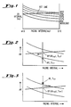
- Figure 1 presents a graph showing a plurality of patient heart curves correlating pacing interval and AV interval for respective different workload conditions, having superimposed thereon a reference line correlating the pacemaker working relationship between AV interval and pacing interval.
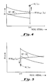
- Figure 2 is a set of curves illustrating the increase of pacing rate under conditions when the measured AV interval is found to be less than the AV reference.
- Figure 3 presents curves illustrating a pacing system response to decreased pacing rate when measured AV interval is found to be greater than the AV reference.
- Figure 4 presents curves illustrating adjustment of the AV reference when the pacing system is operating at lower rate limit.
- Figure 5 presents curves illustrating adjustment of the AV reference interval when the pacing system is operating at upper rate limit.
- Figure 6A is a block diagram of a DDDR pacing system in accordance with this invention
- Figure 6B is a block diagram of an AAIR pacing system in accordance with this invention.
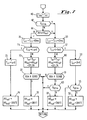
- Figure 7 is a software flow diagram illustrating a method of controlling atrial pacing rate as a function of AV.
- AV is used substantially interchangeably with AR.
- AR interval could be referred to.
- patient heart curves are illustrated which show the variation of AV interval with pacing interval for five different workload values.
- a reference line is shown superimposed over the heart curves, which as illustrated provides a linear relationship between the pacing interval and changes of the AV interval.
- This reference line, or working line is used in the algorithm of this invention, to link pacing intervals and AV intervals. Note that it extends from zero workload at LRL, to maximum workload at URL.
- the AV interval which corresponds with a certain pacing interval is the AV ref value; at each beat the AV interval is measured and compared with the AV ref interval which corresponds to the just completed actual pacing interval.
- the invention is illustrated by a linear relationship, which provides a constant slope or correlation between change in pacing interval and change in AV ref .
- the reference line need not be linear, and optimum results can be obtained for any given patient by adopting a non-linear reference curve to the patient heartbeat curves.
- the pacing system may preferably respond with larger incremental steps at lower pacing rates, than at higher pacing rates which yields a non-linear reference curve.
- the slope may be positive (as shown), negative or in fact zero. If the slope is zero, AV ref is a constant, and pacing rate is changed in a direction to make the patient AV move toward AV ref .
- the principle of the algorithm of this invention is illustrated in a situation where pacing rate is increased due to a sensed shortening of the AV interval.
- the reference point RP is the point on the reference line established during the last pacing cycle.
- the measured value of AV is seen to be less than AV ref , signaling a decrease in interval (in accordance with the arrow) and a corresponding increase in pacing rate.
- a sensed shortening of the AV interval results in a pacing system response with an increased atrial stimulus rate.
- the curves illustrate a decrease in the pacing rate (increase in pacing interval) when an increase in AV interval is sensed.
- the pacing interval is increased 12.8 ms and the AR reference interval is increased by the same increment as it is decreased corresponding to a shortening of the AV interval.
- the pacing interval is adapted by increasing it or decreasing it by a fixed amount, e.g., by 12.8 ms; and the value of AR ref is changed according to the slope of the reference curve. If the measured AR is less than AR ref , then the pacing interval is decreased.
- the AR ref can either be increased or decreased, or remain unchanged, depending upon the slope (positive, zero or negative).
- the change in AR ref can be toward the measured AR interval or away from it, depending on the slope.
- the pacing interval and the AV ref interval are continuously coupled. However, if operation of the pacing system takes the rate to either upper or lower limit, then there is decoupling of the pacing interval and the AV ref interval, effected by a change in the AV ref value only.
- AV ref is incremented by a predetermined factor referred to as drift. This effectively shifts the entire reference line vertically.
- FIGS 6A and 6B there are shown block diagrams illustrative of DDDR and AAIR versions respectively of this invention. It is to be understood that the system of this invention may be utilized in either the dual chamber or single chamber embodiment, and in either case may be in communication with an external programmer (not shown) in a manner well known in the pacemaker industry.
- the hardware and software elements represented by Figures 6A and 6B are well known in the art, as are the techniques of timing out intervals and microprocessor control of pacing functions.
- an implantable pacer at 25 having connected to it an external lead 28 having at least one electrode at about its distal tip adapted to be implanted in the patient's atrium A. It also is connected to an external electrode 30 having at least one electrode at about the distal tip thereof adapted to be implanted in the patient's ventricle. It is to be understood that the system and method of this invention may be practiced using either unilateral or bilateral leads.
- an atrial generator 27 is provided for generating atrial stimulus signals, the output of which is connected to lead 28.
- a ventricular generator 29 for generating ventricular stimulus pulses is connected to lead 30.
- Lead 28 is also connected to A sense circuitry 31, while lead 30 is connected to V sense circuitry 32.
- the A sense circuitry senses atrial heartbeats and may be used to operate the atrial channel in a demand mode. Likewise the V sense circuitry senses the occurrences of natural ventricular responses, or heartbeats, in a well known manner.
- Timer circuitry 33 is suitably used for timing out calculated atrial stimulating intervals, ventricular stimulating intervals, AV intervals, and the like, in a well known fashion. Timer 33 is shown controlled by logic such as that illustrated by a microprocessor ( ⁇ p) at 34. Timing signals are suitably generated under control of microprocessor 34 to provide sense windows to control the sensing of the atrial and ventricular signals at circuits 31 and 32 respectively, in a well known manner. Logic under the control of microprocessor 34 also controls the timing of delivery of atrial pulses from generator 27 and ventricular pulses from generator 28.
- V sense circuitry 38 adapted to sense the far field ventricular signal (R wave) as discussed hereinabove.
- V sense circuitry 38 may in fact be the same sensing hardware as A sense circuitry 31, controlled by different window signals generated by timer 33 and microprocessor 34.
- V sense circuitry 38 comprises conventional hardware having a time response adapted to the known morphology, amplitude and slew rate of the far field ventricular signal sensed by atrial lead 28.
- the first negative ventricular deflections from the sensed far field signal are expected to have a mean of 1.42 mV; a mean duration of 28.9 ms, and a slew rate of 0.05 V/sec.
- the pacemaker first sets the atrial escape interval T aai to the calculated interval T rr , thus establishing atrial pacing rate.
- the pacer determines whether a ventricular stimulus pulse has been delivered. If no, meaning that the natural QRS was sensed, the pacer goes to block 44 in the program. If yes, meaning that no QRS was sensed during the time out of the AV interval, the program branches to block 50.
- a new calculated pacing interval T rr' is computed equal to the prior interval (T rr ) incremented by 12.8 ms.
- This increment in pacing interval which results in a decrease of rate, is performed because of the recognition that the information from the patient's heart concerning AV interval is not present. Under these circumstances, the pacer takes the atrial stimulus rate toward the lower rate limit, by adding a predetermined increment to the interval.
- the program goes to block 60 where the new pacing interval T rr is set equal to T rr' .
- the AV ref is incremented by adding a predetermined amount referred to as delta, corresponding to the slope of the reference line. The value of delta is programmable. As shown at block 63, where the last ventricular event was a V stimulus pulse, the program then exits.
- the program goes to 44 where it is determined whether the measured AV interval is greater than or equal to AV ref . If yes, reflecting an increase in AV, the program branches to block 50 where pacing interval is incremented. See the illustration of Fig. 3. A drift factor will be added at block 56 or subtracted at block 64, depending upon whether the newly computed pacing interval T rr' has increased beyond lrl. If it has, then the program shifts the reference line upward by adding a drift increment at 56, to couple pacing at LRL to the actual AV delay of the patient. See the illustration of Fig. 4.
- T rr' is less than lrl
- the program continues to block 60, as above.
- AV ref is decremented by drift at 64. This drift figure is introduced to increase the internal pacing rate in order to override the heart's intrinsic rate, i.e, the pacer drifts toward a rate at which an atrial stimulus (A stim ) results. This overriding is done in order that the pacemaker can update AV information such that when atrial stimulus signals have to be delivered, they are done so at approximately the desired pacing rate.
- AV ref is adjusted by subtracting the drift amount (suitably 100 ms) in order to adjust the reference curve toward the patient's actual AV value at URL. See the illustration of Fig. 5.
- the interval T rr is adjusted at 76 by setting it equal to the calculated T rr' .
- the new AV ref point is calculated by subtracting the predetermined amount delta from the prior AV ref .
- the determination is made as to whether there have been sixteen consecutive A sense signals. If yes, meaning that overdrive is desired, AV ref is decremented by the drift constant at 78, which biases the atrial pacing rate toward a higher rate.
- the pacing system adapts by incrementing the pacing interval one step (reducing rate) and adapting AV ref according to the slope programmed in the system. If AV interval is less than AV ref , then the pacing interval is decreased one step (increasing rate) and AV ref is adapted downward according to the slope.
- the pacer drifts toward the measured AR interval by decrementing AV ref by the drift increment.
- the pacer drifts toward the measured AR interval by increasing AV ref by the drift increment.
- AV ref is decremented one drift increment in order to increase pacing rate.
- an AV interval reading also occurs after sensed atrial beats.
- the AV interval is then expected to be shorter than the AV interval after an atrial pacing event. This induces a kind of hysteresis. If there are sensed atrial beats, the rate will tend to increase, but when pacing takes over, the rate will tend to decrease. This effect is countered by introducing an offset in AR ref for sensed beats. However, whenever a V stimulus has been delivered, indicating loss of R wave, the reference position is frozen and there is no drift.
- AV (or AR) interval As the control parameter, the software of Fig. 7 is modified to leave out any steps involving V stim . Thus, elements 42, 55 and 63, and the "yes" paths branching therefrom, are not utilized. AV time intervals are obtained by using the far field sensing as discussed above and, of course, the source of the interval data has no effect on the software operation.
Landscapes
- Health & Medical Sciences (AREA)
- Cardiology (AREA)
- Heart & Thoracic Surgery (AREA)
- Life Sciences & Earth Sciences (AREA)
- Biophysics (AREA)
- Physiology (AREA)
- Engineering & Computer Science (AREA)
- Biomedical Technology (AREA)
- Nuclear Medicine, Radiotherapy & Molecular Imaging (AREA)
- Radiology & Medical Imaging (AREA)
- Animal Behavior & Ethology (AREA)
- General Health & Medical Sciences (AREA)
- Public Health (AREA)
- Veterinary Medicine (AREA)
- Electrotherapy Devices (AREA)
- Measurement And Recording Of Electrical Phenomena And Electrical Characteristics Of The Living Body (AREA)
Abstract
Claims (19)
- Système régulateur pour une régulation à sensibilité fréquentielle des oreillettes d'un patient, ce système étant pourvu d'un générateur auriculaire (27) adapté pour produire et envoyer des impulsions de stimulus auriculaire à une fréquence auriculaire variable, de moyens (28, 31) de détection auriculaire adaptés pour détecter les pulsations auriculaires et de moyens d'analyse AV (31, 32, 33) adaptés pour déterminer l'intervalle de temps AV s'écoulant entre un événement auriculaire et la détection d'une pulsation ventriculaire lui succédant, caractérisé par des moyens de détection de champ lointain (28, 38) pourvus d'une électrode placée dans l'oreillette du patient et adaptée pour détecter les pulsations ventriculaires de champ lointain répondant à des pulsations auriculaires; des moyens de calcul de référence (60, 76) adaptés pour fixer une valeur de référence AV correspondant à l'intervalle AV déterminé, des moyens de comparaison adaptés pour comparer l'intervalle AV à la référence AV (44); et des moyens (50, 70) de réglage de la fréquence adaptés pour faire varier la fréquence auriculaire et donc, l'intervalle de régulation auriculaire, en fonction de la comparaison établie.
- Système régulateur selon la revendication 1, dans lequel les moyens de calcul de référence corrigent la valeur de référence AV consécutivement à une variation de l'intervalle de régulation auriculaire.
- Système régulateur selon la revendication 2, dans lequel les moyens de calcul de référence diminuent la valeur de référence AV en lui soustrayant un incrément prédéfini lorsque l'on détermine une valeur de l'intervalle AV inférieure à la valeur de référence AV (76).
- Système régulateur selon la revendication 2, dans lequel les moyens de calcul de référence augmentent la valeur de référence AV en lui ajoutant un incrément prédéfini lorsque l'on détermine une valeur de l'intervalle AV supérieure à la valeur de référence AV (60).
- Système régulateur selon la revendication 1, comprenant, en outre, des moyens (29) adaptés pour envoyer des stimuli ventriculaires au ventricule du patient lorsqu'aucune pulsation ventriculaire n'a été détectée, et des moyens (56) adaptés pour incrémenter encore l'intervalle de régulation auriculaire consécutivement à l'envoi d'un stimulus ventriculaire.
- Système régulateur selon la revendication 1, comprenant, en outre, des moyens (61, 77) adaptés pour déterminer si un modèle prédéfini de pulsations auriculaires naturelles s'est produit, et des moyens (64, 74) adaptés pour diminuer la valeur de référence AV d'un incrément prédéfini consécutivement à l'analyse du modèle de pulsations auriculaires naturelles, amenant ainsi le système régulateur à prendre le pas sur les pulsations auriculaires naturelles, de manière à envoyer un stimulus auriculaire.
- Système régulateur selon la revendication 1, dans lequel les moyens de calcul de référence agissent à chaque cycle du système régulateur.
- Système régulateur selon la revendication 7, dans lequel les moyens de calcul de référence corrigent la valeur de référence AV avec un premier incrément prédéfini et en ce que les moyens de réglage de la fréquence modifient l'intervalle de régulation auriculaire avec un deuxième incrément prédéfini.
- Système régulateur selon la revendication 8, comprenant des moyens adaptés pour programmer les premier et deuxième incréments.
- Système régulateur selon la revendication 9, dans lequel le rapport entre les premier et deuxième incréments est maintenu sensiblement constant pour toutes les fréquences de régulation auriculaire.
- Système régulateur selon la revendication 10, dans lequel le générateur auriculaire peut être réglé sur n'importe quelle fréquence d'une gage de fréquences prédéfinie et en ce que la relation entre les premier et deuxième incréments est une fonction non-linéaire de la fréquence auriculaire.
- Système régulateur selon la revendication 8, comprenant des moyens adaptés pour fixer les premier et deuxième incréments en leur donnant une valeur plus grande aux fréquences auriculaires basses qu'aux fréquences auriculaires élevées.
- Système régulateur selon la revendication 1, comprenant un stimulateur cardiaque implanté et un fil unique connecté à celui-ci, le fil auriculaire unique étant pourvu d'une électrode adaptée pour être placée dans l'oreillette du patient et étant pourvu d'un arrangement permettant à des électrodes de détecter les pulsations ventriculaires de champ lointain, ainsi que les pulsations auriculaires.
- Système régulateur selon la revendication 1, dans lequel les moyens de calcul de référence sont des moyens adaptés pour modifier la valeur de référence AV à chaque fois que la fréquence de régulation auriculaire est changée.
- Système régulateur selon la revendication 1, comprenant des moyens (74) adaptés pour apporter une correction supplémentaire à la valeur de référence AV lorsque l'intervalle d'échappement modifié correspond à une fréquence supérieure à une fréquence limite supérieure prédéfinie.
- Système régulateur selon la revendication 1, comprenant des moyens (56) adaptés pour apporter une correction supplémentaire à la valeur de référence AV lorsque l'intervalle d'échappement modifié correspond à une fréquence inférieure à une fréquence limite inférieure prédéfinie.
- Système régulateur selon la revendication 1, comportant un stimulateur cardiaque de type DDDR.
- Système régulateur selon la revendication 1, comportant un stimulateur cardiaque de type AAIR.
- Système régulateur pourvu de moyens adaptés pour commander la fréquence d'envoi d'impulsions de stimulus auriculaire à une oreillette d'un patient, comportant un stimulateur cardiaque (25) pourvu d'un générateur (27) de stimulus auriculaire et d'un fil auriculaire (28) reliant au moins une électrode située dans l'oreillette au stimulateur cardiaque, ce dernier étant pourvu de moyens (33) de chronométrage adaptés pour mesurer l'intervalle de temps AV s'écoulant entre l'envoi d'impulsions auriculaires et la détection d'événements ventriculaires, ce système régulateur étant caractérisé par des moyens de détection (38) adaptés pour détecter des événéments ventriculaires de champ lointain à partir d'au moins une électrode, les moyens de chronométrage recevant les événéments ventriculaires détectés, et des moyens (33, 34) de réglage de la fréquence adaptés pour corriger la fréquence de régulation auriculaire qui est fonction de l'intervalle AV déterminé.
Applications Claiming Priority (3)
| Application Number | Priority Date | Filing Date | Title |
|---|---|---|---|
| US575238 | 1990-08-30 | ||
| US07/575,238 US5144950A (en) | 1990-08-30 | 1990-08-30 | Rate controlled pacemaker system using ar interval for rate control |
| PCT/EP1991/001511 WO1992004076A1 (fr) | 1990-08-30 | 1991-08-08 | Systeme de stimulateur cardiaque a frequence commandee utilisant l'intervalle ar pour la commande de la frequence |
Publications (2)
| Publication Number | Publication Date |
|---|---|
| EP0545967A1 EP0545967A1 (fr) | 1993-06-16 |
| EP0545967B1 true EP0545967B1 (fr) | 1994-12-07 |
Family
ID=24299481
Family Applications (1)
| Application Number | Title | Priority Date | Filing Date |
|---|---|---|---|
| EP91914576A Revoked EP0545967B1 (fr) | 1990-08-30 | 1991-08-08 | Systeme de stimulateur cardiaque a frequence commandee utilisant l'intervalle ar pour la commande de la frequence |
Country Status (8)
| Country | Link |
|---|---|
| US (1) | US5144950A (fr) |
| EP (1) | EP0545967B1 (fr) |
| JP (1) | JPH06502554A (fr) |
| AU (1) | AU647172B2 (fr) |
| CA (1) | CA2088241A1 (fr) |
| DE (1) | DE69105738T2 (fr) |
| ES (1) | ES2065052T3 (fr) |
| WO (1) | WO1992004076A1 (fr) |
Families Citing this family (135)
| Publication number | Priority date | Publication date | Assignee | Title |
|---|---|---|---|---|
| US5228438A (en) * | 1991-10-08 | 1993-07-20 | Siemens Pacesetter, Inc. | Implantable pacemaker including means and method of terminating a pacemaker-mediated tachycardia during rate adaptive pacing |
| EP0578793B1 (fr) * | 1992-02-03 | 1996-11-20 | Medtronic, Inc. | Systeme de stimulateur cardiaque a chambre double utilise pour fournir des impulsions auriculaires synchrones |
| US5247929A (en) * | 1992-02-04 | 1993-09-28 | Vitatron Medical, B.V. | Dual chamber pacemaker with AV extension and PMT control |
| SE9202630D0 (sv) * | 1992-09-14 | 1992-09-14 | Hans Schueller | Pacemaker |
| US5312447A (en) * | 1992-09-24 | 1994-05-17 | Vitatron Medical, B.V. | Pacemaker with improved inhibit and trigger control |
| US5312452A (en) * | 1992-11-03 | 1994-05-17 | Cardiac Pacemakers, Inc. | Cardiac rhythm management device with automatic optimization of performance related pacing parameters |
| US5340361A (en) * | 1992-11-13 | 1994-08-23 | Siemens Pacesetter, Inc. | Implantable pacemaker having adaptive AV interval adoptively shortened to assure ventricular pacing |
| US5741308A (en) * | 1992-11-13 | 1998-04-21 | Pacesetter, Inc. | Dual-chamber implantable pacemaker and method of operating same for automatically setting the pacemaker's AV interval as a function of a natural measured conduction time |
| US5814077A (en) * | 1992-11-13 | 1998-09-29 | Pacesetter, Inc. | Pacemaker and method of operating same that provides functional atrial cardiac pacing with ventricular support |
| US5334220A (en) * | 1992-11-13 | 1994-08-02 | Siemens Pacesetter, Inc. | Dual-chamber implantable pacemaker having an adaptive AV interval that prevents ventricular fusion beats and method of operating same |
| US5330511A (en) * | 1993-01-19 | 1994-07-19 | Vitatron Medical B.V. | Dual chamber pacemaker with automatically optimized AV delay |
| US5411531A (en) * | 1993-09-23 | 1995-05-02 | Medtronic, Inc. | Method and apparatus for control of A-V interval |
| US5514163A (en) | 1995-02-21 | 1996-05-07 | Medtronic, Inc. | Dual chamber pacing system and method with optimized adjustment of the AV escape interval for treating cardiomyopathy |
| US5626620A (en) * | 1995-02-21 | 1997-05-06 | Medtronic, Inc. | Dual chamber pacing system and method with continual adjustment of the AV escape interval so as to maintain optimized ventricular pacing for treating cardiomyopathy |
| US5527347A (en) | 1995-02-21 | 1996-06-18 | Medtronic, Inc. | Dual chamber pacing system and method with automatic adjustment of the AV escape interval for treating cardiomyopathy |
| DE69628906T2 (de) * | 1995-09-29 | 2004-05-19 | Medtronic, Inc., Minneapolis | Anpassungsfähige suche der av verzögerung |
| US5683426A (en) * | 1996-08-29 | 1997-11-04 | Pacesetter, Inc. | Apparatus and method for detecting the progression of AV nodal block and atrial capture |
| DE19758109A1 (de) * | 1997-12-17 | 1999-06-24 | Biotronik Mess & Therapieg | Herzstimulator |
| US6370656B1 (en) * | 1998-11-19 | 2002-04-09 | Compaq Information Technologies, Group L. P. | Computer system with adaptive heartbeat |
| DE19859653A1 (de) | 1998-12-15 | 2000-06-21 | Biotronik Mess & Therapieg | Selbstkalibrierender ratenadaptiver Herzschrittmacher |
| US7738955B2 (en) * | 2000-12-21 | 2010-06-15 | Medtronic, Inc. | System and method for ventricular pacing with AV interval modulation |
| US7245966B2 (en) | 2000-12-21 | 2007-07-17 | Medtronic, Inc. | Ventricular event filtering for an implantable medical device |
| US9931509B2 (en) | 2000-12-21 | 2018-04-03 | Medtronic, Inc. | Fully inhibited dual chamber pacing mode |
| US6694189B2 (en) * | 2001-03-07 | 2004-02-17 | Medtronic, Inc. | Rate adaptive pacemaker system with dual sensing component and method of using same |
| US7248924B2 (en) * | 2004-10-25 | 2007-07-24 | Medtronic, Inc. | Self limited rate response |
| US7542799B2 (en) * | 2005-01-21 | 2009-06-02 | Medtronic, Inc. | Implantable medical device with ventricular pacing protocol |
| US7593773B2 (en) * | 2005-01-21 | 2009-09-22 | Medtronic, Inc. | Implantable medical device with ventricular pacing protocol including progressive conduction search |
| US8391990B2 (en) | 2005-05-18 | 2013-03-05 | Cardiac Pacemakers, Inc. | Modular antitachyarrhythmia therapy system |
| US7925344B2 (en) * | 2006-01-20 | 2011-04-12 | Medtronic, Inc. | System and method of using AV conduction timing |
| US8046063B2 (en) | 2006-02-28 | 2011-10-25 | Medtronic, Inc. | Implantable medical device with adaptive operation |
| US7894898B2 (en) * | 2006-06-15 | 2011-02-22 | Medtronic, Inc. | System and method for ventricular interval smoothing following a premature ventricular contraction |
| US7869872B2 (en) * | 2006-06-15 | 2011-01-11 | Medtronic, Inc. | System and method for determining intrinsic AV interval timing |
| US7783350B2 (en) * | 2006-06-15 | 2010-08-24 | Medtronic, Inc. | System and method for promoting intrinsic conduction through atrial timing modification and calculation of timing parameters |
| US7565196B2 (en) * | 2006-06-15 | 2009-07-21 | Medtronic, Inc. | System and method for promoting intrinsic conduction through atrial timing |
| US7502647B2 (en) | 2006-07-31 | 2009-03-10 | Medtronic, Inc. | Rate smoothing pacing modality with increased ventricular sensing |
| US7720537B2 (en) | 2006-07-31 | 2010-05-18 | Medtronic, Inc. | System and method for providing improved atrial pacing based on physiological need |
| US7715914B2 (en) * | 2006-07-31 | 2010-05-11 | Medtronic, Inc. | System and method for improving ventricular sensing |
| US7502646B2 (en) * | 2006-07-31 | 2009-03-10 | Medtronic, Inc. | Pacing mode event classification with rate smoothing and increased ventricular sensing |
| US7515958B2 (en) | 2006-07-31 | 2009-04-07 | Medtronic, Inc. | System and method for altering pacing modality |
| US7689281B2 (en) | 2006-07-31 | 2010-03-30 | Medtronic, Inc. | Pacing mode event classification with increased ventricular sensing |
| US7856269B2 (en) | 2006-07-31 | 2010-12-21 | Medtronic, Inc. | System and method for determining phsyiologic events during pacing mode operation |
| US8244354B2 (en) * | 2009-02-27 | 2012-08-14 | Medtronic, Inc. | System and method for conditional biventricular pacing |
| WO2010099382A1 (fr) * | 2009-02-27 | 2010-09-02 | Medtronic, Inc. | Système et procédé de stimulation biventriculaire conditionnelle |
| US8265750B2 (en) * | 2009-02-27 | 2012-09-11 | Medtronic, Inc. | System and method for conditional biventricular pacing |
| US8923963B2 (en) | 2012-10-31 | 2014-12-30 | Medtronic, Inc. | Leadless pacemaker system |
| US9808633B2 (en) * | 2012-10-31 | 2017-11-07 | Medtronic, Inc. | Leadless pacemaker system |
| US9789319B2 (en) | 2013-11-21 | 2017-10-17 | Medtronic, Inc. | Systems and methods for leadless cardiac resynchronization therapy |
| US9592391B2 (en) | 2014-01-10 | 2017-03-14 | Cardiac Pacemakers, Inc. | Systems and methods for detecting cardiac arrhythmias |
| WO2015106007A1 (fr) | 2014-01-10 | 2015-07-16 | Cardiac Pacemakers, Inc. | Procédés et systèmes pour communication améliorée entre des dispositifs médicaux |
| US9492671B2 (en) | 2014-05-06 | 2016-11-15 | Medtronic, Inc. | Acoustically triggered therapy delivery |
| US9669224B2 (en) | 2014-05-06 | 2017-06-06 | Medtronic, Inc. | Triggered pacing system |
| EP3185952B1 (fr) | 2014-08-28 | 2018-07-25 | Cardiac Pacemakers, Inc. | Système implantable pour le suivi du rythme cardiaque et un procédé associé pour déclencher une période de suppression par un second dispositif |
| ES2713231T3 (es) | 2015-02-06 | 2019-05-20 | Cardiac Pacemakers Inc | Sistemas para el suministro seguro de una terapia de estimulación eléctrica |
| US9669230B2 (en) | 2015-02-06 | 2017-06-06 | Cardiac Pacemakers, Inc. | Systems and methods for treating cardiac arrhythmias |
| WO2016130477A2 (fr) | 2015-02-09 | 2016-08-18 | Cardiac Pacemakers, Inc. | Dispositif médical implantable comportant une étiquette d'identification radio-opaque |
| US11285326B2 (en) | 2015-03-04 | 2022-03-29 | Cardiac Pacemakers, Inc. | Systems and methods for treating cardiac arrhythmias |
| US10050700B2 (en) | 2015-03-18 | 2018-08-14 | Cardiac Pacemakers, Inc. | Communications in a medical device system with temporal optimization |
| WO2016149262A1 (fr) | 2015-03-18 | 2016-09-22 | Cardiac Pacemakers, Inc. | Communications dans un système de dispositif médical avec une évaluation de qualité de liaison |
| WO2017031221A1 (fr) | 2015-08-20 | 2017-02-23 | Cardiac Pacemakers, Inc. | Systèmes et procédés de communication entre des dispositifs médicaux |
| CN108136187B (zh) | 2015-08-20 | 2021-06-29 | 心脏起搏器股份公司 | 用于医疗装置之间的通信的系统和方法 |
| US9956414B2 (en) | 2015-08-27 | 2018-05-01 | Cardiac Pacemakers, Inc. | Temporal configuration of a motion sensor in an implantable medical device |
| US9968787B2 (en) | 2015-08-27 | 2018-05-15 | Cardiac Pacemakers, Inc. | Spatial configuration of a motion sensor in an implantable medical device |
| US10226631B2 (en) | 2015-08-28 | 2019-03-12 | Cardiac Pacemakers, Inc. | Systems and methods for infarct detection |
| EP3341076B1 (fr) | 2015-08-28 | 2022-05-11 | Cardiac Pacemakers, Inc. | Systèmes et procédés pour l'administration de thérapie et la détection de signal sensible au comportement |
| WO2017040115A1 (fr) | 2015-08-28 | 2017-03-09 | Cardiac Pacemakers, Inc. | Système de détection de tamponnade |
| US10092760B2 (en) | 2015-09-11 | 2018-10-09 | Cardiac Pacemakers, Inc. | Arrhythmia detection and confirmation |
| WO2017062806A1 (fr) | 2015-10-08 | 2017-04-13 | Cardiac Pacemakers, Inc. | Dispositifs et procédés pour ajuster des fréquences de stimulation dans un dispositif médical implantable |
| EP3389775B1 (fr) | 2015-12-17 | 2019-09-25 | Cardiac Pacemakers, Inc. | Communication menée dans un système de dispositif médical |
| US10905886B2 (en) | 2015-12-28 | 2021-02-02 | Cardiac Pacemakers, Inc. | Implantable medical device for deployment across the atrioventricular septum |
| WO2017127548A1 (fr) | 2016-01-19 | 2017-07-27 | Cardiac Pacemakers, Inc. | Dispositifs permettant de recharger sans fil une batterie rechargeable d'un dispositif médical implantable |
| EP3411113B1 (fr) | 2016-02-04 | 2019-11-27 | Cardiac Pacemakers, Inc. | Système de pose avec capteur de force pour dispositif cardiaque sans fil |
| US9731138B1 (en) | 2016-02-17 | 2017-08-15 | Medtronic, Inc. | System and method for cardiac pacing |
| WO2017173275A1 (fr) | 2016-03-31 | 2017-10-05 | Cardiac Pacemakers, Inc. | Dispositif médical implantable à batterie rechargeable |
| US9802055B2 (en) | 2016-04-04 | 2017-10-31 | Medtronic, Inc. | Ultrasound powered pulse delivery device |
| US10668294B2 (en) | 2016-05-10 | 2020-06-02 | Cardiac Pacemakers, Inc. | Leadless cardiac pacemaker configured for over the wire delivery |
| US10328272B2 (en) | 2016-05-10 | 2019-06-25 | Cardiac Pacemakers, Inc. | Retrievability for implantable medical devices |
| CN109414582B (zh) | 2016-06-27 | 2022-10-28 | 心脏起搏器股份公司 | 使用皮下感测p波进行再同步起搏管理的心脏治疗系统 |
| US11207527B2 (en) | 2016-07-06 | 2021-12-28 | Cardiac Pacemakers, Inc. | Method and system for determining an atrial contraction timing fiducial in a leadless cardiac pacemaker system |
| WO2018009392A1 (fr) | 2016-07-07 | 2018-01-11 | Cardiac Pacemakers, Inc. | Stimulateur cardiaque sans fil utilisant des mesures de pression pour la vérification de la capture de stimulation |
| EP3487579B1 (fr) | 2016-07-20 | 2020-11-25 | Cardiac Pacemakers, Inc. | Système de repère de synchronisation de contraction auriculaire dans un stimulateur cardiaque sans fil. |
| EP3500342B1 (fr) | 2016-08-19 | 2020-05-13 | Cardiac Pacemakers, Inc. | Dispositif médical implantable trans-septal |
| WO2018039335A1 (fr) | 2016-08-24 | 2018-03-01 | Cardiac Pacemakers, Inc. | Thérapie intégrée de resynchronisation cardiaque à dispositifs multiples utilisant l'onde p pour stimuler la synchronisation. |
| US10870008B2 (en) | 2016-08-24 | 2020-12-22 | Cardiac Pacemakers, Inc. | Cardiac resynchronization using fusion promotion for timing management |
| WO2018057318A1 (fr) | 2016-09-21 | 2018-03-29 | Cardiac Pacemakers, Inc. | Dispositif de stimulation sans fil muni d'un boîtier qui abrite des composants interne du dispositif de stimulation sans fil et fonctionne comme boîtier de batterie et borne d'une batterie interne |
| WO2018057626A1 (fr) | 2016-09-21 | 2018-03-29 | Cardiac Pacemakers, Inc. | Moniteur cardiaque implantable |
| US10758737B2 (en) | 2016-09-21 | 2020-09-01 | Cardiac Pacemakers, Inc. | Using sensor data from an intracardially implanted medical device to influence operation of an extracardially implantable cardioverter |
| US10463305B2 (en) | 2016-10-27 | 2019-11-05 | Cardiac Pacemakers, Inc. | Multi-device cardiac resynchronization therapy with timing enhancements |
| EP3532159B1 (fr) | 2016-10-27 | 2021-12-22 | Cardiac Pacemakers, Inc. | Système de pose de dispositif médical implantable avec capteur intégré |
| EP3532161B1 (fr) | 2016-10-27 | 2023-08-30 | Cardiac Pacemakers, Inc. | Dispositif médical implantable à capteur de pression |
| US10561330B2 (en) | 2016-10-27 | 2020-02-18 | Cardiac Pacemakers, Inc. | Implantable medical device having a sense channel with performance adjustment |
| US10413733B2 (en) | 2016-10-27 | 2019-09-17 | Cardiac Pacemakers, Inc. | Implantable medical device with gyroscope |
| EP3532160B1 (fr) | 2016-10-27 | 2023-01-25 | Cardiac Pacemakers, Inc. | Dispositif séparé pour gérer l'énergie d'impulsion de stimulation d'un stimulateur cardiaque |
| US10617874B2 (en) | 2016-10-31 | 2020-04-14 | Cardiac Pacemakers, Inc. | Systems and methods for activity level pacing |
| WO2018081721A1 (fr) | 2016-10-31 | 2018-05-03 | Cardiac Pacemakers, Inc | Systèmes de stimulation de niveau d'activité |
| US10583301B2 (en) | 2016-11-08 | 2020-03-10 | Cardiac Pacemakers, Inc. | Implantable medical device for atrial deployment |
| EP3538213B1 (fr) | 2016-11-09 | 2023-04-12 | Cardiac Pacemakers, Inc. | Systèmes et dispositifs pour régler des paramètres d'impulsion de stimulation cardiaque pour un dispositif de stimulation cardiaque |
| US10894163B2 (en) | 2016-11-21 | 2021-01-19 | Cardiac Pacemakers, Inc. | LCP based predictive timing for cardiac resynchronization |
| US11147979B2 (en) | 2016-11-21 | 2021-10-19 | Cardiac Pacemakers, Inc. | Implantable medical device with a magnetically permeable housing and an inductive coil disposed about the housing |
| US10639486B2 (en) | 2016-11-21 | 2020-05-05 | Cardiac Pacemakers, Inc. | Implantable medical device with recharge coil |
| US10881869B2 (en) | 2016-11-21 | 2021-01-05 | Cardiac Pacemakers, Inc. | Wireless re-charge of an implantable medical device |
| EP3541473B1 (fr) | 2016-11-21 | 2020-11-11 | Cardiac Pacemakers, Inc. | Stimulateur cardiaque sans sonde à communication multimodale |
| US11207532B2 (en) | 2017-01-04 | 2021-12-28 | Cardiac Pacemakers, Inc. | Dynamic sensing updates using postural input in a multiple device cardiac rhythm management system |
| WO2018140623A1 (fr) | 2017-01-26 | 2018-08-02 | Cardiac Pacemakers, Inc. | Dispositif sans fil présentant des composants surmoulés |
| WO2018140797A1 (fr) | 2017-01-26 | 2018-08-02 | Cardiac Pacemakers, Inc. | Dispositif implantable sans fil à fixation amovible |
| US10835753B2 (en) | 2017-01-26 | 2020-11-17 | Cardiac Pacemakers, Inc. | Intra-body device communication with redundant message transmission |
| US10905872B2 (en) | 2017-04-03 | 2021-02-02 | Cardiac Pacemakers, Inc. | Implantable medical device with a movable electrode biased toward an extended position |
| AU2018248361B2 (en) | 2017-04-03 | 2020-08-27 | Cardiac Pacemakers, Inc. | Cardiac pacemaker with pacing pulse energy adjustment based on sensed heart rate |
| WO2019036600A1 (fr) | 2017-08-18 | 2019-02-21 | Cardiac Pacemakers, Inc. | Dispositif médical implantable avec capteur de pression |
| WO2019036568A1 (fr) | 2017-08-18 | 2019-02-21 | Cardiac Pacemakers, Inc. | Dispositif médical implantable comprenant un concentrateur de flux et une bobine de réception disposée autour du concentrateur de flux |
| JP6938778B2 (ja) | 2017-09-20 | 2021-09-22 | カーディアック ペースメイカーズ, インコーポレイテッド | 複数の作動モードを備えた移植式医療用装置 |
| US11185703B2 (en) | 2017-11-07 | 2021-11-30 | Cardiac Pacemakers, Inc. | Leadless cardiac pacemaker for bundle of his pacing |
| US11813463B2 (en) | 2017-12-01 | 2023-11-14 | Cardiac Pacemakers, Inc. | Leadless cardiac pacemaker with reversionary behavior |
| EP3717063B1 (fr) | 2017-12-01 | 2023-12-27 | Cardiac Pacemakers, Inc. | Systèmes pour détecter des repères de synchronisation de contraction auriculaire et pour déterminer un intervalle cardiaque à partir d'un stimulateur cardiaque sans fil implanté de manière ventriculaire |
| CN111417433B (zh) | 2017-12-01 | 2024-04-30 | 心脏起搏器股份公司 | 从心室植入的无引线心脏起搏器检测心室充盈期间心房收缩定时基准的方法和系统 |
| CN111432874A (zh) | 2017-12-01 | 2020-07-17 | 心脏起搏器股份公司 | 从心室植入的无引线心脏起搏器检测搜索窗口内心房收缩定时基准的方法和系统 |
| US11529523B2 (en) | 2018-01-04 | 2022-12-20 | Cardiac Pacemakers, Inc. | Handheld bridge device for providing a communication bridge between an implanted medical device and a smartphone |
| CN111556773A (zh) | 2018-01-04 | 2020-08-18 | 心脏起搏器股份公司 | 无逐搏通信的双腔起搏 |
| JP2021518192A (ja) | 2018-03-23 | 2021-08-02 | メドトロニック,インコーポレイテッド | VfA心臓再同期治療 |
| CN111886046B (zh) | 2018-03-23 | 2025-05-27 | 美敦力公司 | Av同步vfa心脏治疗 |
| CN111936046B (zh) | 2018-03-23 | 2024-06-28 | 美敦力公司 | 用于心动过速的vfa心脏治疗 |
| US10596383B2 (en) | 2018-04-03 | 2020-03-24 | Medtronic, Inc. | Feature based sensing for leadless pacing therapy |
| US11235161B2 (en) | 2018-09-26 | 2022-02-01 | Medtronic, Inc. | Capture in ventricle-from-atrium cardiac therapy |
| US11951313B2 (en) | 2018-11-17 | 2024-04-09 | Medtronic, Inc. | VFA delivery systems and methods |
| US12296177B2 (en) | 2018-12-21 | 2025-05-13 | Medtronic, Inc. | Delivery systems and methods for left ventricular pacing |
| US11679265B2 (en) | 2019-02-14 | 2023-06-20 | Medtronic, Inc. | Lead-in-lead systems and methods for cardiac therapy |
| US11697025B2 (en) | 2019-03-29 | 2023-07-11 | Medtronic, Inc. | Cardiac conduction system capture |
| US11213676B2 (en) | 2019-04-01 | 2022-01-04 | Medtronic, Inc. | Delivery systems for VfA cardiac therapy |
| US11712188B2 (en) | 2019-05-07 | 2023-08-01 | Medtronic, Inc. | Posterior left bundle branch engagement |
| US11305127B2 (en) | 2019-08-26 | 2022-04-19 | Medtronic Inc. | VfA delivery and implant region detection |
| US11813466B2 (en) | 2020-01-27 | 2023-11-14 | Medtronic, Inc. | Atrioventricular nodal stimulation |
| US12543992B2 (en) | 2020-03-30 | 2026-02-10 | Medtronic, Inc. | Pacing efficacy determination using a representative morphology of external cardiac signals |
| US11911168B2 (en) | 2020-04-03 | 2024-02-27 | Medtronic, Inc. | Cardiac conduction system therapy benefit determination |
| US12605103B2 (en) | 2020-05-21 | 2026-04-21 | Medtronic, Inc. | QRS detection and bracketing |
| US12465770B2 (en) | 2020-07-31 | 2025-11-11 | Medtronic, Inc. | Coronary sinus conduction system pacing and delivery |
| US11813464B2 (en) | 2020-07-31 | 2023-11-14 | Medtronic, Inc. | Cardiac conduction system evaluation |
Citations (5)
| Publication number | Priority date | Publication date | Assignee | Title |
|---|---|---|---|---|
| EP0218739A1 (fr) * | 1985-10-14 | 1987-04-22 | Schleifring und Apparatebau GmbH | Joint rotatif optique pour la transmission à voies multiples de signaux lumineux |
| EP0255899A1 (fr) * | 1986-07-31 | 1988-02-17 | Werner Prof. Dr.-Ing. Irnich | Stimulateur cardiaque à fréquence adaptable |
| US5172694A (en) * | 1991-05-30 | 1992-12-22 | Vitatron Medical B.V. | Single pacing lead and method utilizing two different floating bipoles |
| US5400796A (en) * | 1992-10-28 | 1995-03-28 | Siemens-Elema Ab | Device for identifying atrial depolarization |
| US5427949A (en) * | 1991-03-07 | 1995-06-27 | Dade International Inc. | Biosynthetic cerebrospinal fluid control |
Family Cites Families (16)
| Publication number | Priority date | Publication date | Assignee | Title |
|---|---|---|---|---|
| USRE28003E (en) * | 1969-06-12 | 1974-05-07 | Electronic demand heart pacemaker with different pacing and standby rates | |
| US3656487A (en) * | 1969-06-12 | 1972-04-18 | Medtronic Inc | Electronic demand heart pacemaker with different pacing and standby rates |
| US3857399A (en) * | 1970-03-24 | 1974-12-31 | F Zacouto | Heart pacer |
| GB1424355A (en) * | 1972-03-11 | 1976-02-11 | Kent Cambridge Medical Ltd | Cardiac pacers |
| US4284082A (en) * | 1979-12-12 | 1981-08-18 | Medtronic B.V.Kerkrade | Ventricular synchronized atrial pacemaker and method of operation |
| US4387717A (en) * | 1980-10-03 | 1983-06-14 | Research Corporation | Pacer internal cardiac electrogram sensing system |
| US4493325A (en) * | 1982-05-03 | 1985-01-15 | Medtronic, Inc. | Tachyarrhythmia pacer |
| DE3247264A1 (de) * | 1982-12-21 | 1984-06-28 | Siemens AG, 1000 Berlin und 8000 München | Bifokaler herzschrittmacher mit zwei unipolaren elektroden |
| US4527568A (en) * | 1983-12-27 | 1985-07-09 | Vitafin N.V. | Dual chamber pacer with alternative rate adaptive means and method |
| US4644954A (en) * | 1984-01-10 | 1987-02-24 | Vitafin N.V. | Rate adaptive pacemaker apparatus and method |
| US4686988A (en) * | 1984-10-19 | 1987-08-18 | Sholder Jason A | Pacemaker system and method for measuring and monitoring cardiac activity and for determining and maintaining capture |
| DE3535568A1 (de) * | 1985-10-04 | 1987-04-09 | Siemens Ag | Vorhofgesteuerter herzschrittmacher |
| DE3535543A1 (de) * | 1985-10-04 | 1987-04-09 | Siemens Ag | Vorhofgesteuerter herzschrittmacher |
| US4799486A (en) * | 1987-03-13 | 1989-01-24 | Cardiac Pacemakers, Inc. | Refractoriless atrial sensing in dual chamber pacemakers |
| US4856524A (en) * | 1988-08-29 | 1989-08-15 | Intermedics, Inc. | A-V responsive rate adaptive pacemaker |
| US4972834A (en) * | 1988-09-30 | 1990-11-27 | Vitatron Medical B.V. | Pacemaker with improved dynamic rate responsiveness |
-
1990
- 1990-08-30 US US07/575,238 patent/US5144950A/en not_active Expired - Fee Related
-
1991
- 1991-08-08 DE DE69105738T patent/DE69105738T2/de not_active Revoked
- 1991-08-08 AU AU83326/91A patent/AU647172B2/en not_active Ceased
- 1991-08-08 EP EP91914576A patent/EP0545967B1/fr not_active Revoked
- 1991-08-08 WO PCT/EP1991/001511 patent/WO1992004076A1/fr not_active Ceased
- 1991-08-08 ES ES91914576T patent/ES2065052T3/es not_active Expired - Lifetime
- 1991-08-08 CA CA002088241A patent/CA2088241A1/fr not_active Abandoned
- 1991-08-08 JP JP3513428A patent/JPH06502554A/ja active Pending
Patent Citations (5)
| Publication number | Priority date | Publication date | Assignee | Title |
|---|---|---|---|---|
| EP0218739A1 (fr) * | 1985-10-14 | 1987-04-22 | Schleifring und Apparatebau GmbH | Joint rotatif optique pour la transmission à voies multiples de signaux lumineux |
| EP0255899A1 (fr) * | 1986-07-31 | 1988-02-17 | Werner Prof. Dr.-Ing. Irnich | Stimulateur cardiaque à fréquence adaptable |
| US5427949A (en) * | 1991-03-07 | 1995-06-27 | Dade International Inc. | Biosynthetic cerebrospinal fluid control |
| US5172694A (en) * | 1991-05-30 | 1992-12-22 | Vitatron Medical B.V. | Single pacing lead and method utilizing two different floating bipoles |
| US5400796A (en) * | 1992-10-28 | 1995-03-28 | Siemens-Elema Ab | Device for identifying atrial depolarization |
Non-Patent Citations (1)
| Title |
|---|
| J. Beyer, F. Weber and B. Lüderitz, "Long-Term Results with Atrial Pacing and Atrial Triggered Pacemaker Systems", Book from Second European Symposium on Cardiac Pacing, Florence, May 3rd to May 6th, 1981, pages 655 - 658 * |
Also Published As
| Publication number | Publication date |
|---|---|
| JPH06502554A (ja) | 1994-03-24 |
| US5144950A (en) | 1992-09-08 |
| AU647172B2 (en) | 1994-03-17 |
| DE69105738D1 (de) | 1995-01-19 |
| CA2088241A1 (fr) | 1992-03-01 |
| DE69105738T2 (de) | 1995-06-29 |
| WO1992004076A1 (fr) | 1992-03-19 |
| AU8332691A (en) | 1992-03-30 |
| EP0545967A1 (fr) | 1993-06-16 |
| ES2065052T3 (es) | 1995-02-01 |
Similar Documents
| Publication | Publication Date | Title |
|---|---|---|
| US5144950A (en) | Rate controlled pacemaker system using ar interval for rate control | |
| EP0361517B1 (fr) | Système de stimulateur cardiaque a taux adaptif | |
| US4856524A (en) | A-V responsive rate adaptive pacemaker | |
| US5065759A (en) | Pacemaker with optimized rate responsiveness and method of rate control | |
| EP0621055B1 (fr) | Stimulateur cardiaque avec ajustement de son rythme selon les informations issues d'un capteur en fonction du rythme sinusal détecté | |
| EP0596598B1 (fr) | Dispositif de contrôle du rythme cardiaque à optimalisation automatique des paramètres de stimulation | |
| US4644954A (en) | Rate adaptive pacemaker apparatus and method | |
| US5549649A (en) | Programmable pacemaker including an atrial rate filter for deriving a filtered atrial rate used for switching pacing modes | |
| US5527347A (en) | Dual chamber pacing system and method with automatic adjustment of the AV escape interval for treating cardiomyopathy | |
| EP0652029B1 (fr) | Système de stimulation double chambre avec fréquence adaptative avec réglage automatique des paramètres d'opération | |
| US8626289B2 (en) | Method and system for delivering cardiac resynchronization therapy with variable atrio-ventricular delay | |
| US5749906A (en) | Dual chamber pacing system and method with continual adjustment of the AV escape interval so as to maintain optimized ventricular pacing for treating cardiomyopathy | |
| US5226413A (en) | Rate responsive pacemaker and method for automatically initializing the same | |
| EP0841075B1 (fr) | Système de stimulation cardiaque bi-cavité permettant le réglage de l'intervalle AV | |
| EP0870516B1 (fr) | Stimulateur cardiaque à détection améliorée de la réaction évoquée et du signal de répolarisation | |
| US7389141B2 (en) | Biatrial pacing optimization for biventricular pacing | |
| US5944743A (en) | Pacemaker system and method with special function rate response | |
| EP0148486B1 (fr) | Appareil d'entraînement se conformant à la fréquence | |
| EP0861677B1 (fr) | Stimulateur cardiaque à hystérèse améliorée |
Legal Events
| Date | Code | Title | Description |
|---|---|---|---|
| PUAI | Public reference made under article 153(3) epc to a published international application that has entered the european phase |
Free format text: ORIGINAL CODE: 0009012 |
|
| 17P | Request for examination filed |
Effective date: 19930323 |
|
| AK | Designated contracting states |
Kind code of ref document: A1 Designated state(s): BE DE ES FR GB IT NL SE |
|
| 17Q | First examination report despatched |
Effective date: 19931005 |
|
| GRAA | (expected) grant |
Free format text: ORIGINAL CODE: 0009210 |
|
| AK | Designated contracting states |
Kind code of ref document: B1 Designated state(s): BE DE ES FR GB IT NL SE |
|
| REF | Corresponds to: |
Ref document number: 69105738 Country of ref document: DE Date of ref document: 19950119 |
|
| EAL | Se: european patent in force in sweden |
Ref document number: 91914576.3 |
|
| REG | Reference to a national code |
Ref country code: ES Ref legal event code: FG2A Ref document number: 2065052 Country of ref document: ES Kind code of ref document: T3 |
|
| ET | Fr: translation filed | ||
| ITF | It: translation for a ep patent filed | ||
| PLBI | Opposition filed |
Free format text: ORIGINAL CODE: 0009260 |
|
| 26 | Opposition filed |
Opponent name: BIOTRONIK MESS- UND THERAPIEGERAETE GMBH & CO INGE Effective date: 19950907 |
|
| NLR1 | Nl: opposition has been filed with the epo |
Opponent name: BIOTRONIK MESS- UND THERAPIEGERAETE GMBH & CO INGE |
|
| PLBF | Reply of patent proprietor to notice(s) of opposition |
Free format text: ORIGINAL CODE: EPIDOS OBSO |
|
| PGFP | Annual fee paid to national office [announced via postgrant information from national office to epo] |
Ref country code: FR Payment date: 19960729 Year of fee payment: 6 |
|
| PGFP | Annual fee paid to national office [announced via postgrant information from national office to epo] |
Ref country code: GB Payment date: 19960731 Year of fee payment: 6 |
|
| PGFP | Annual fee paid to national office [announced via postgrant information from national office to epo] |
Ref country code: ES Payment date: 19960812 Year of fee payment: 6 Ref country code: BE Payment date: 19960812 Year of fee payment: 6 |
|
| PGFP | Annual fee paid to national office [announced via postgrant information from national office to epo] |
Ref country code: SE Payment date: 19960819 Year of fee payment: 6 |
|
| PGFP | Annual fee paid to national office [announced via postgrant information from national office to epo] |
Ref country code: NL Payment date: 19960831 Year of fee payment: 6 |
|
| PG25 | Lapsed in a contracting state [announced via postgrant information from national office to epo] |
Ref country code: GB Free format text: LAPSE BECAUSE OF NON-PAYMENT OF DUE FEES Effective date: 19970808 |
|
| PG25 | Lapsed in a contracting state [announced via postgrant information from national office to epo] |
Ref country code: SE Free format text: LAPSE BECAUSE OF NON-PAYMENT OF DUE FEES Effective date: 19970809 Ref country code: ES Free format text: LAPSE BECAUSE OF NON-PAYMENT OF DUE FEES Effective date: 19970809 |
|
| PG25 | Lapsed in a contracting state [announced via postgrant information from national office to epo] |
Ref country code: BE Free format text: LAPSE BECAUSE OF NON-PAYMENT OF DUE FEES Effective date: 19970831 |
|
| PGFP | Annual fee paid to national office [announced via postgrant information from national office to epo] |
Ref country code: DE Payment date: 19971028 Year of fee payment: 7 |
|
| BERE | Be: lapsed |
Owner name: VITATRON MEDICAL B.V. Effective date: 19970831 |
|
| PG25 | Lapsed in a contracting state [announced via postgrant information from national office to epo] |
Ref country code: NL Free format text: LAPSE BECAUSE OF NON-PAYMENT OF DUE FEES Effective date: 19980301 |
|
| GBPC | Gb: european patent ceased through non-payment of renewal fee |
Effective date: 19970808 |
|
| PG25 | Lapsed in a contracting state [announced via postgrant information from national office to epo] |
Ref country code: FR Free format text: LAPSE BECAUSE OF NON-PAYMENT OF DUE FEES Effective date: 19980430 |
|
| EUG | Se: european patent has lapsed |
Ref document number: 91914576.3 |
|
| NLV4 | Nl: lapsed or anulled due to non-payment of the annual fee |
Effective date: 19980301 |
|
| REG | Reference to a national code |
Ref country code: FR Ref legal event code: ST |
|
| PLAW | Interlocutory decision in opposition |
Free format text: ORIGINAL CODE: EPIDOS IDOP |
|
| PLAW | Interlocutory decision in opposition |
Free format text: ORIGINAL CODE: EPIDOS IDOP |
|
| PG25 | Lapsed in a contracting state [announced via postgrant information from national office to epo] |
Ref country code: DE Free format text: LAPSE BECAUSE OF NON-PAYMENT OF DUE FEES Effective date: 19990601 |
|
| RDAH | Patent revoked |
Free format text: ORIGINAL CODE: EPIDOS REVO |
|
| RDAG | Patent revoked |
Free format text: ORIGINAL CODE: 0009271 |
|
| STAA | Information on the status of an ep patent application or granted ep patent |
Free format text: STATUS: PATENT REVOKED |
|
| 27W | Patent revoked |
Effective date: 19990815 |