EP0545986B1 - Procede de fonctionnement d'un vehicule mobile guide par fil, dans l'air ou l'eau et dispositif de mise en application du procede - Google Patents
Procede de fonctionnement d'un vehicule mobile guide par fil, dans l'air ou l'eau et dispositif de mise en application du procede Download PDFInfo
- Publication number
- EP0545986B1 EP0545986B1 EP91914948A EP91914948A EP0545986B1 EP 0545986 B1 EP0545986 B1 EP 0545986B1 EP 91914948 A EP91914948 A EP 91914948A EP 91914948 A EP91914948 A EP 91914948A EP 0545986 B1 EP0545986 B1 EP 0545986B1
- Authority
- EP
- European Patent Office
- Prior art keywords
- support
- vehicle
- wire
- buoyancy
- reconnaissance
- Prior art date
- Legal status (The legal status is an assumption and is not a legal conclusion. Google has not performed a legal analysis and makes no representation as to the accuracy of the status listed.)
- Expired - Lifetime
Links
- XLYOFNOQVPJJNP-UHFFFAOYSA-N water Substances O XLYOFNOQVPJJNP-UHFFFAOYSA-N 0.000 title claims abstract description 13
- 238000000034 method Methods 0.000 title claims abstract description 9
- 238000004804 winding Methods 0.000 claims abstract description 12
- 239000000463 material Substances 0.000 claims description 2
- 230000007423 decrease Effects 0.000 claims 1
- 239000013307 optical fiber Substances 0.000 description 4
- 230000005540 biological transmission Effects 0.000 description 3
- 238000004891 communication Methods 0.000 description 2
- 241000251729 Elasmobranchii Species 0.000 description 1
- 239000004677 Nylon Substances 0.000 description 1
- 230000001133 acceleration Effects 0.000 description 1
- 230000003213 activating effect Effects 0.000 description 1
- 230000015572 biosynthetic process Effects 0.000 description 1
- 238000004364 calculation method Methods 0.000 description 1
- 230000003247 decreasing effect Effects 0.000 description 1
- 238000002592 echocardiography Methods 0.000 description 1
- 230000000694 effects Effects 0.000 description 1
- 239000000835 fiber Substances 0.000 description 1
- 239000011152 fibreglass Substances 0.000 description 1
- 238000005755 formation reaction Methods 0.000 description 1
- 238000003032 molecular docking Methods 0.000 description 1
- 229920001778 nylon Polymers 0.000 description 1
- 239000004033 plastic Substances 0.000 description 1
- 230000011514 reflex Effects 0.000 description 1
- 239000002990 reinforced plastic Substances 0.000 description 1
- 238000012876 topography Methods 0.000 description 1
- 239000003643 water by type Substances 0.000 description 1
Images




Classifications
-
- G—PHYSICS
- G01—MEASURING; TESTING
- G01V—GEOPHYSICS; GRAVITATIONAL MEASUREMENTS; DETECTING MASSES OR OBJECTS; TAGS
- G01V1/00—Seismology; Seismic or acoustic prospecting or detecting
- G01V1/38—Seismology; Seismic or acoustic prospecting or detecting specially adapted for water-covered areas
- G01V1/3843—Deployment of seismic devices, e.g. of streamers
-
- B—PERFORMING OPERATIONS; TRANSPORTING
- B63—SHIPS OR OTHER WATERBORNE VESSELS; RELATED EQUIPMENT
- B63C—LAUNCHING, HAULING-OUT, OR DRY-DOCKING OF VESSELS; LIFE-SAVING IN WATER; EQUIPMENT FOR DWELLING OR WORKING UNDER WATER; MEANS FOR SALVAGING OR SEARCHING FOR UNDERWATER OBJECTS
- B63C11/00—Equipment for dwelling or working underwater; Means for searching for underwater objects
- B63C11/48—Means for searching for underwater objects
-
- F—MECHANICAL ENGINEERING; LIGHTING; HEATING; WEAPONS; BLASTING
- F42—AMMUNITION; BLASTING
- F42B—EXPLOSIVE CHARGES, e.g. FOR BLASTING, FIREWORKS, AMMUNITION
- F42B22/00—Marine mines, e.g. launched by surface vessels or submarines
- F42B22/10—Moored mines
- F42B22/14—Moored mines at a variable depth setting
- F42B22/16—Moored mines at a variable depth setting using mechanical means, e.g. plummet and float
Definitions
- the present invention relates to a method to operate a control wire-guided, in air or water, movable vehicle and a device for carrying out the method.
- the invention has emerged when starting from problems concerning underwater vehicles or put in another way, torpedoes and will therefore mainly be symbolizefied with such.
- the present problem exist, however, also in an application with air vehicles and also in this case it can be solved in the same way, so the invention relates also to such vehicles.
- a possible solution to the raised problem is to use some form of a wire-guided torpedo-mine, that is a wire guided torpedo that rests on a support on the bottom until it is activated, whereupon it swims away on its commission. It is in this case possible to have an operator on the shore, connected to the support with a cable, for example an optical fibre, for communication and possibly also an usual two-wire cable for power supply.
- a cable for example an optical fibre, for communication and possibly also an usual two-wire cable for power supply.
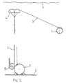
- the embodiment that is shown in the figures relates to a reconnaissance and/or weapon system for underwater use and comprises a vehicle 1, in the following in the description of this system called torpedo, and a support 2 for it.
- the support is connected with an operator site, preferably on the shore, with a wire connection.
- This wire which is intended to lie still, preferably has a higher density than that of water, so it lies on the bottom.
- the support 2 is connected to the torpedo 1 with a wire 3, here called the control wire, which has a density somewhat lower than that of water. The wire will therefore float in the water and does therefore not strive to lie down on the bottom.
- wire magazines from which the wire is fed out, when the torpedo leaves.
- wire magazines both in the support 2 and the torpedo 1.
- a wire magazine in one end of the wire is enough.
- a reconnaissance torpedo travels about for quite a long time, during which the distance to the support is reduced from time to time, moreover it returns at intervals to a rest position on the support. In this case a wire magazine that is able to wind or reel the wire back is needed. Also in the case with a weapon torpedo this can be of interest as the target can make sharp turns etc.
- the invention overcomes by being provided with a device 4 having buoyancy, in this underwater application in the following called float, connected to the support 2 and being arranged to be able to raise the control wire 3 from the bottom 5 to a position close to the surface 6.
- the float 4 consists of a floating body that is attached to one or more lines 7, which are possible to wind on a winding apparatus 8.
- the winding apparatus can be controlled to unwind and then wind a suitable part of the line or lines 7.
- the control wire 3 runs from the support 2, through a hole in the float 4 and further to the torpedo 1.
- line or lines 7 are provided with transversal struts 9. They thereby create a device looking like a rope-ladder.
- the distance between the struts 9 is suitably shorter than the length of the adjacent struts 9, which will prevent them from getting entangled by one strut being stuck into an adjacent gap.
- the "rope-ladder” is suitably designed with gradually shorter struts counted from the support 2 towards the float 4 and thereby it also has a decreasing distance between the struts.
- the "rope-ladder” hereby becomes more difficult to detect with a hydroacoustical sensor, as the interference between reflexes from the struts is avoided.
- the struts 9 can be made of tubes of fibreglass reinforced plastic. Through the tubes, between the longitudinal lines 7, a nylon line is drawn, which is of the same kind as the one the longitudinal lines are made from.
- the outer diameter of the struts could for instance be 7 mm and their inner diameter 5 mm.
- the float 4 is a toroid, and the control wire 3 runs through the central hole of the toroid.
- the toroid consists of a hard and smooth shell, made for instance of plastic, which on the inside is filled up with a pressure resistant floating material, for instance bonocell.
- accumulators in the support 2. These can either be charged via the wire from the operator site or from thermic batteries in the support, which are activated as the need for charging current arises. Also in the torpedo 1 there are accumulatos, that are charged from the support 2, when the torpedo is in its rest position.
- the float 4 can either at first be released an adapted length by means of the winding apparatus 8 and then the torpedo 1 be released from a locking device, for example in the form of a motor-driven or magneticly driven male contact on the torpedo, which is in contact with a female contact on the support, the contacts are also at the same time used to feed charging current. Then the torpedo is givenbuoyancy, for instance by emplying a water-bag in the torpedo or by activating water-jets in the torpedo directed downwards. Thereafter the propulsion engines are started. Alternatively the torpedo 1 can be released before the float 4 or on the whole at the same time.
- a locking device for example in the form of a motor-driven or magneticly driven male contact on the torpedo, which is in contact with a female contact on the support, the contacts are also at the same time used to feed charging current. Then the torpedo is givenbuoyancy, for instance by emplying a water-bag
- the corresponding technique can, after a certain adjustment, be used also for atmosphere vehicles, such as wire guided helicopters or propelled airships.
- control wire 3 in the underwater case is an optical fibre, it must have a special water-resistant sheath, which will make it thicker. It is, however, easy to give it a density that is somewhat lower than that of water.
- the wire 3 can for obvious reasons not be lighter than air, but an optical fibre does not in this case need an advanced sheath and can be made very thin and light, so that the wire tension between the vehicle and the lifting device 4 can keep it up.
Landscapes
- Life Sciences & Earth Sciences (AREA)
- Physics & Mathematics (AREA)
- Engineering & Computer Science (AREA)
- Acoustics & Sound (AREA)
- General Life Sciences & Earth Sciences (AREA)
- Mechanical Engineering (AREA)
- Geology (AREA)
- Remote Sensing (AREA)
- Oceanography (AREA)
- General Physics & Mathematics (AREA)
- Geophysics (AREA)
- Environmental & Geological Engineering (AREA)
- Ocean & Marine Engineering (AREA)
- General Engineering & Computer Science (AREA)
- Aiming, Guidance, Guns With A Light Source, Armor, Camouflage, And Targets (AREA)
- Control Of Position, Course, Altitude, Or Attitude Of Moving Bodies (AREA)
- Toys (AREA)
- Emergency Lowering Means (AREA)
- Fire-Extinguishing By Fire Departments, And Fire-Extinguishing Equipment And Control Thereof (AREA)
Abstract
Claims (10)
- Procédé pour faire fonctionner un véhicule mobile (1) guidé par fil de commande, dans l'air ou l'eau, à partir d'un support (2), caractérisé en ce que le véhicule et/ou le support est muni d'un magasin de fil pour le fil de commande (3), en ce que le support est muni d'un appareil d'enroulement (8) et d'un dispositif de flotteur (4) fixé à une ou plusieurs lignes (7) disposées pour être enroulées ou dévidées par l'appareil d'enroulement (8) et présentant une position de repos sur le support ou au voisinage du support, en ce que le fil de commande (3) du véhicule est tiré du support à travers un trou formé dans le dispositif de flotteur (4), en ce qu'au moment du lancement du véhicule (1) on fait dévider à l'appareil d'enroulement (8) une longueur prédéterminée de la ligne ou des lignes (7) de façon que le dispositif de flotteur (4) monte jusqu'à la hauteur permise par la ligne ou les lignes, tandis que le fil de commande (3) est tiré hors du magasin ou des magasins de fil, et en ce que le véhicule (1), est amené à quitter le support (2), avant, après ou en même temps que le dispositif de flotteur (4) et puis, pendant le mouvement, doit recevoir une information de guidage provenant du support, et éventuellement renvoyer une information provenant d'un détecteur installé dans le véhicule.
- Procédé selon la revendication 1, caractérisé en ce que le véhicule (1), au retour vers sa position de repos, est tout d'abord guidé jusqu'à une position située au-dessus du support (2), après quoi, dans un ordre optionnel ou simultanément, le dispositif de flotteur (4) est tiré vers le bas par l'appareil d'enroulement (8) jusqu'à sa position de repos, tandis qu'on fait descendre le véhicule jusqu'à sa position de repos.
- Système de reconnaissance et/ou système d'arme comprenant un véhicule mobile (1) guidé par fil de commande, dans l'air ou l'eau, et un support (2) pour celui-ci, caractérisé en ce que le véhicule et/ou le support comporte un magasin de fil pour le fil de commande (3), en ce que le support est muni d'un appareil d'enroulement (8) et d'un dispositif de flotteur (4) fixé à une ou plusieurs lignes (7) disposées pour être enroulées ou dévidées par l'appareil d'enroulement (8), et présentant une position de repos sur le support ou au voisinage du support (2), et en ce que le fil de commande (3) du véhicule est tiré du support à travers un trou formé dans le dispositif de flotteur (4), vers le véhicule.
- Système de reconnaissance et/ou système d'arme selon la revendication 3, caractérisé en ce que la ligne ou les lignes (7) sont constituées de deux lignes qui sont munies d'entretoises transversales (9) suivant leurs longueurs, de manière à créer un dispositif en forme d'échelle de corde dans lequel la distance entre les entretoises est plus courte que la longueur des entretoises adjacentes.
- Système de reconnaissance et/ou système d'arme selon la revendication 4, caractérisé en ce que la longueur des entretoises (9) diminue lorsqu'on va du support vers le dispositif de flotteur (4).
- Système de reconnaissance et/ou système d'arme selon la revendication 4 ou 5, caractérisé en ce que les entretoises (9) sont constituées par des tubes dans lesquels passe une ligne transversale entre les lignes longitudinales (7), cette ligne transversale étant réalisée dans le même matériau que les lignes longitudinales.
- Système de reconnaissance et/ou système d'arme selon l'une des revendication 3 à 6, caractérisé en ce que le dispositif de flotteur (4) est un toroïde et en ce que le fil de commande passe dans son trou central.
- Système de reconnaissance et/ou système d'arme selon l'une des revendication 3 à 7, caractérisé en ce que le système est un système sous-marin dans lequel le véhicule (1) est une torpille de reconnaissance ou une torpille offensive et en ce que le fil de commande (3) présente une densité légèrement plus faible que celle de l'eau.
- Système de reconnaissance et/ou système d'arme selon l'une des revendication 3 à 7, caractérisé en ce que le système est un système atmosphérique dans lequel le véhicule (1) est un aéronef ayant un système de propulsion.
- Système de reconnaissance et/ou système d'arme selon l'une des revendication 3 à 7, caractérisé en ce que le système est un système atmosphérique dans lequel le véhicule (1) est un hélicoptère commandé à distance.
Applications Claiming Priority (3)
| Application Number | Priority Date | Filing Date | Title |
|---|---|---|---|
| SE9002760A SE466927B (sv) | 1990-08-29 | 1990-08-29 | Saett att operera med en traadstyrd, i luft eller vatten roerlig farkost och en anordning foer att genomfoera saettet |
| SE9002760 | 1990-08-29 | ||
| PCT/SE1991/000560 WO1992004590A1 (fr) | 1990-08-29 | 1991-08-23 | Procede de fonctionnement d'un vehicule mobile guide par fil, dans l'air ou l'eau et dispositif de mise en application du procede |
Publications (2)
| Publication Number | Publication Date |
|---|---|
| EP0545986A1 EP0545986A1 (fr) | 1993-06-16 |
| EP0545986B1 true EP0545986B1 (fr) | 1995-07-05 |
Family
ID=20380231
Family Applications (1)
| Application Number | Title | Priority Date | Filing Date |
|---|---|---|---|
| EP91914948A Expired - Lifetime EP0545986B1 (fr) | 1990-08-29 | 1991-08-23 | Procede de fonctionnement d'un vehicule mobile guide par fil, dans l'air ou l'eau et dispositif de mise en application du procede |
Country Status (8)
| Country | Link |
|---|---|
| US (1) | US5377164A (fr) |
| EP (1) | EP0545986B1 (fr) |
| CA (1) | CA2088362A1 (fr) |
| DE (1) | DE69111071D1 (fr) |
| FI (1) | FI930895A0 (fr) |
| NO (1) | NO302439B1 (fr) |
| SE (1) | SE466927B (fr) |
| WO (1) | WO1992004590A1 (fr) |
Cited By (1)
| Publication number | Priority date | Publication date | Assignee | Title |
|---|---|---|---|---|
| CN104076399A (zh) * | 2014-06-06 | 2014-10-01 | 中国石油集团东方地球物理勘探有限责任公司 | 一种扇贝养殖区海底电缆地震采集施工方法 |
Families Citing this family (6)
| Publication number | Priority date | Publication date | Assignee | Title |
|---|---|---|---|---|
| FR2722164B1 (fr) * | 1994-07-08 | 1996-09-13 | Eca | Procede perfectionne de destruction d'un objet sous-marin, notamment d'une mine immergee |
| US5503059A (en) * | 1995-01-03 | 1996-04-02 | Pacholok; David R. | Vehicle disabling device and method |
| US5637826A (en) * | 1996-02-07 | 1997-06-10 | The United States Of America As Represented By The Secretary Of The Navy | Method and apparatus for optimal guidance |
| US6738314B1 (en) | 2003-01-31 | 2004-05-18 | L3 Communications Corporation | Autonomous mine neutralization system |
| US6712312B1 (en) * | 2003-01-31 | 2004-03-30 | The United States Of America As Represented By The Secretary Of The Navy | Reconnaissance using unmanned surface vehicles and unmanned micro-aerial vehicles |
| WO2008093289A1 (fr) * | 2007-01-31 | 2008-08-07 | Armscor Business (Pty) Ltd T/A Institute For Maritime Technology | Système de bouée sous-marine |
Family Cites Families (5)
| Publication number | Priority date | Publication date | Assignee | Title |
|---|---|---|---|---|
| US2422337A (en) * | 1940-04-19 | 1947-06-17 | Chilowsky Constantin | Submarine detecting buoy |
| US3161168A (en) * | 1961-09-28 | 1964-12-15 | Loral Electronics Corp | Submarine self-propelling device |
| US4004265A (en) * | 1974-08-02 | 1977-01-18 | Sanders Associates, Inc. | Self-propelled array system |
| US4557697A (en) * | 1982-07-22 | 1985-12-10 | Institut Okeanologii Imeni P.P. Shirshova | Method of delivering to ocean bottom and raising to surface of station for deep water researches and design of station delivered using said method |
| US4794575A (en) * | 1987-10-02 | 1988-12-27 | The United States Of America As Represented By The Secretary Of The Navy | Submarine launched sea-state buoy (SLSSB) |
-
1990
- 1990-08-29 SE SE9002760A patent/SE466927B/sv not_active IP Right Cessation
-
1991
- 1991-08-23 DE DE69111071T patent/DE69111071D1/de not_active Expired - Lifetime
- 1991-08-23 CA CA002088362A patent/CA2088362A1/fr not_active Abandoned
- 1991-08-23 EP EP91914948A patent/EP0545986B1/fr not_active Expired - Lifetime
- 1991-08-23 US US08/039,323 patent/US5377164A/en not_active Expired - Fee Related
- 1991-08-23 WO PCT/SE1991/000560 patent/WO1992004590A1/fr not_active Ceased
-
1993
- 1993-02-26 FI FI930895A patent/FI930895A0/fi unknown
- 1993-02-26 NO NO930730A patent/NO302439B1/no unknown
Cited By (2)
| Publication number | Priority date | Publication date | Assignee | Title |
|---|---|---|---|---|
| CN104076399A (zh) * | 2014-06-06 | 2014-10-01 | 中国石油集团东方地球物理勘探有限责任公司 | 一种扇贝养殖区海底电缆地震采集施工方法 |
| CN104076399B (zh) * | 2014-06-06 | 2017-03-01 | 中国石油集团东方地球物理勘探有限责任公司 | 一种扇贝养殖区海底电缆地震采集施工方法 |
Also Published As
| Publication number | Publication date |
|---|---|
| NO930730L (no) | 1993-04-29 |
| US5377164A (en) | 1994-12-27 |
| SE466927B (sv) | 1992-04-27 |
| DE69111071D1 (de) | 1995-08-10 |
| NO930730D0 (no) | 1993-02-26 |
| FI930895A7 (fi) | 1993-02-26 |
| CA2088362A1 (fr) | 1992-03-01 |
| WO1992004590A1 (fr) | 1992-03-19 |
| SE9002760D0 (sv) | 1990-08-29 |
| FI930895A0 (fi) | 1993-02-26 |
| NO302439B1 (no) | 1998-03-02 |
| SE9002760L (sv) | 1992-03-01 |
| EP0545986A1 (fr) | 1993-06-16 |
Similar Documents
| Publication | Publication Date | Title |
|---|---|---|
| US3880103A (en) | Tethered mine hunting system | |
| US4004265A (en) | Self-propelled array system | |
| US20200010193A1 (en) | Method and Apparatus for Unmanned Aerial Maritime Float Vehicle That Sense and Report Relevant Data from Physical and Operational Environment | |
| US6600695B1 (en) | Method and apparatus for retrieving an unmanned underwater vehicle | |
| US8831393B2 (en) | Unmanned underwater vehicle and device for connection of an optical waveguide cable to an unmanned underwater vehicle | |
| US4272835A (en) | Master buoy system for acoustic array deployment, using underwater glide bodies remotely launched from a submerged pod | |
| US4185580A (en) | Submarine system | |
| US8817574B2 (en) | Method and system of a compound buoy | |
| NO20151033L (no) | Aktiv styring av marine seismiske kilder | |
| JP2813558B2 (ja) | 海中物体破壊方法 | |
| EP3835834A1 (fr) | Noeud de capteur | |
| WO2009023058A2 (fr) | Véhicule sous-marin hybride autonome ou actionné à distance | |
| JP6595900B2 (ja) | 自律型無人潜水機 | |
| EP0545986B1 (fr) | Procede de fonctionnement d'un vehicule mobile guide par fil, dans l'air ou l'eau et dispositif de mise en application du procede | |
| US20140060417A1 (en) | Unmanned Underwater Vehicle Launcher | |
| US6536743B2 (en) | Fixed umbilical cable flotation docking head | |
| US4494938A (en) | Master buoy system for acoustic array deployment, using underwater glide bodies remotely launched from a submerged pod | |
| Ferguson | The Theseus autonomous underwater vehicle. Two successful missions | |
| US5248978A (en) | Underwater guide vehicle for removal of submerged and floating navigational hazards | |
| US5419512A (en) | Towed fiber optic data link payout system | |
| US3946695A (en) | Self-deploying multiple anchor mooring systems | |
| Murashima et al. | Thin cable system for ROV and AUV in JAMSTEC | |
| US6612244B1 (en) | Method and device for destroying drifting sea mines | |
| DE102017128319A1 (de) | Boje zur Unterstützung der Navigation und/oder Kommunikation eines U-Bootes | |
| Aoki et al. | Development of deep sea free swimming ROV" UROV7K" |
Legal Events
| Date | Code | Title | Description |
|---|---|---|---|
| PUAI | Public reference made under article 153(3) epc to a published international application that has entered the european phase |
Free format text: ORIGINAL CODE: 0009012 |
|
| 17P | Request for examination filed |
Effective date: 19930325 |
|
| AK | Designated contracting states |
Kind code of ref document: A1 Designated state(s): CH DE DK ES FR GB GR IT LI |
|
| 17Q | First examination report despatched |
Effective date: 19941212 |
|
| RAP1 | Party data changed (applicant data changed or rights of an application transferred) |
Owner name: FOERSVARETS FORSKNINGSANSTALT |
|
| GRAA | (expected) grant |
Free format text: ORIGINAL CODE: 0009210 |
|
| AK | Designated contracting states |
Kind code of ref document: B1 Designated state(s): CH DE DK ES FR GB GR IT LI |
|
| PG25 | Lapsed in a contracting state [announced via postgrant information from national office to epo] |
Ref country code: ES Free format text: THE PATENT HAS BEEN ANNULLED BY A DECISION OF A NATIONAL AUTHORITY Effective date: 19950705 Ref country code: FR Effective date: 19950705 Ref country code: LI Effective date: 19950705 Ref country code: DK Effective date: 19950705 Ref country code: GR Free format text: LAPSE BECAUSE OF FAILURE TO SUBMIT A TRANSLATION OF THE DESCRIPTION OR TO PAY THE FEE WITHIN THE PRESCRIBED TIME-LIMIT Effective date: 19950705 Ref country code: CH Effective date: 19950705 Ref country code: IT Free format text: LAPSE BECAUSE OF FAILURE TO SUBMIT A TRANSLATION OF THE DESCRIPTION OR TO PAY THE FEE WITHIN THE PRE;WARNING: LAPSES OF ITALIAN PATENTS WITH EFFECTIVE DATE BEFORE 2007 MAY HAVE OCCURRED AT ANY TIME BEFORE 2007. THE CORRECT EFFECTIVE DATE MAY BE DIFFERENT FROM THE ONE RECORDED.SCRIBED TIME-LIMIT Effective date: 19950705 |
|
| REF | Corresponds to: |
Ref document number: 69111071 Country of ref document: DE Date of ref document: 19950810 |
|
| PG25 | Lapsed in a contracting state [announced via postgrant information from national office to epo] |
Ref country code: GB Effective date: 19951005 |
|
| PG25 | Lapsed in a contracting state [announced via postgrant information from national office to epo] |
Ref country code: DE Effective date: 19951006 |
|
| REG | Reference to a national code |
Ref country code: CH Ref legal event code: PL |
|
| EN | Fr: translation not filed | ||
| PLBE | No opposition filed within time limit |
Free format text: ORIGINAL CODE: 0009261 |
|
| STAA | Information on the status of an ep patent application or granted ep patent |
Free format text: STATUS: NO OPPOSITION FILED WITHIN TIME LIMIT |
|
| GBPC | Gb: european patent ceased through non-payment of renewal fee |
Effective date: 19951005 |
|
| 26N | No opposition filed |