EP0546505A1 - Connecteur de puissance à distribution de courant - Google Patents
Connecteur de puissance à distribution de courant Download PDFInfo
- Publication number
- EP0546505A1 EP0546505A1 EP92120918A EP92120918A EP0546505A1 EP 0546505 A1 EP0546505 A1 EP 0546505A1 EP 92120918 A EP92120918 A EP 92120918A EP 92120918 A EP92120918 A EP 92120918A EP 0546505 A1 EP0546505 A1 EP 0546505A1
- Authority
- EP
- European Patent Office
- Prior art keywords
- receptacle
- connector
- contact
- contacts
- fingers
- Prior art date
- Legal status (The legal status is an assumption and is not a legal conclusion. Google has not performed a legal analysis and makes no representation as to the accuracy of the status listed.)
- Ceased
Links
Images


Classifications
-
- H—ELECTRICITY
- H01—ELECTRIC ELEMENTS
- H01R—ELECTRICALLY-CONDUCTIVE CONNECTIONS; STRUCTURAL ASSOCIATIONS OF A PLURALITY OF MUTUALLY-INSULATED ELECTRICAL CONNECTING ELEMENTS; COUPLING DEVICES; CURRENT COLLECTORS
- H01R12/00—Structural associations of a plurality of mutually-insulated electrical connecting elements, specially adapted for printed circuits, e.g. printed circuit boards [PCB], flat or ribbon cables, or like generally planar structures, e.g. terminal strips, terminal blocks; Coupling devices specially adapted for printed circuits, flat or ribbon cables, or like generally planar structures; Terminals specially adapted for contact with, or insertion into, printed circuits, flat or ribbon cables, or like generally planar structures
- H01R12/70—Coupling devices
- H01R12/7088—Arrangements for power supply
-
- H—ELECTRICITY
- H01—ELECTRIC ELEMENTS
- H01R—ELECTRICALLY-CONDUCTIVE CONNECTIONS; STRUCTURAL ASSOCIATIONS OF A PLURALITY OF MUTUALLY-INSULATED ELECTRICAL CONNECTING ELEMENTS; COUPLING DEVICES; CURRENT COLLECTORS
- H01R12/00—Structural associations of a plurality of mutually-insulated electrical connecting elements, specially adapted for printed circuits, e.g. printed circuit boards [PCB], flat or ribbon cables, or like generally planar structures, e.g. terminal strips, terminal blocks; Coupling devices specially adapted for printed circuits, flat or ribbon cables, or like generally planar structures; Terminals specially adapted for contact with, or insertion into, printed circuits, flat or ribbon cables, or like generally planar structures
- H01R12/50—Fixed connections
- H01R12/51—Fixed connections for rigid printed circuits or like structures
- H01R12/55—Fixed connections for rigid printed circuits or like structures characterised by the terminals
- H01R12/58—Fixed connections for rigid printed circuits or like structures characterised by the terminals terminals for insertion into holes
-
- H—ELECTRICITY
- H01—ELECTRIC ELEMENTS
- H01R—ELECTRICALLY-CONDUCTIVE CONNECTIONS; STRUCTURAL ASSOCIATIONS OF A PLURALITY OF MUTUALLY-INSULATED ELECTRICAL CONNECTING ELEMENTS; COUPLING DEVICES; CURRENT COLLECTORS
- H01R13/00—Details of coupling devices of the kinds covered by groups H01R12/70 or H01R24/00 - H01R33/00
- H01R13/02—Contact members
- H01R13/10—Sockets for co-operation with pins or blades
- H01R13/11—Resilient sockets
- H01R13/113—Resilient sockets co-operating with pins or blades having a rectangular transverse section
-
- Y—GENERAL TAGGING OF NEW TECHNOLOGICAL DEVELOPMENTS; GENERAL TAGGING OF CROSS-SECTIONAL TECHNOLOGIES SPANNING OVER SEVERAL SECTIONS OF THE IPC; TECHNICAL SUBJECTS COVERED BY FORMER USPC CROSS-REFERENCE ART COLLECTIONS [XRACs] AND DIGESTS
- Y10—TECHNICAL SUBJECTS COVERED BY FORMER USPC
- Y10S—TECHNICAL SUBJECTS COVERED BY FORMER USPC CROSS-REFERENCE ART COLLECTIONS [XRACs] AND DIGESTS
- Y10S439/00—Electrical connectors
- Y10S439/947—PCB mounted connector with ground terminal
Definitions
- This invention relates to a power connector for interconnecting power between circuit boards or the like.
- U.S. Patent Number 4,755,145 teaches an electrically connecting circuit board system featuring bus bars on the upper surface of a backplane board which are engaged by fork-like contacts mounted on a daughter board. In this way, power is supplied to a daughter board to supply components on such board with power.
- the bus bars utilized in the patented system are open with the mating fork-like contacts shrouded in a housing.
- bus bars are positioned side by side on the backplane board to carry different power levels in terms of voltage and current and the bus bars are made relatively heavy in terms of current capacity. As compared with the solid bus bars of the system, the individual contacts on the daughter board are relatively small and fragile.
- the present invention includes a power connector comprised of mating plug and receptacle contacts, each including a series of relatively small posts adapted to fit within and be joined to the thin conductive trace formed by additive or subtractive processes on circuit boards including backplanes, mother boards, and daughter boards.
- Each of the contacts has a common, heavy, current-carrying portion joined to the post portions adapted to handle currents in the tens of amperes range.
- the plug contact includes a blade joining a plurality of posts that are on centers to fit with a daughter board and further includes a housing that links the plug contact mechanically to a signal connector also mounted on a daughter board.
- the receptacle contact includes a plurality of spring fingers which engage the plug contact upon insertion of the plug into the receptacle in a manner allowing repeated engagement and disengagement of the plug within the receptacle, with minimum wear of the contact traces on the plug caused by the fingers of the receptacle. This is accomplished by staggering the fingers so that they engage the surface of the plug at different points with respect to the axis of insertion of the plug within the receptacle.
- the receptacle further includes a plurality of posts which are of a size and on centers to mate with holes and be terminated to conductive traces on or within a mother board.
- the receptacle is "probe-proof" meaning that an operator assembling or disassembling boards cannot touch the circuits of the receptacle half and further, that extraneous conductive material cannot short out the power circuits by falling across an exposed bus bar or across exposed contacts on the mother board.
- the invention contemplates uses of the power contact in multiples to carry power and/or ground circuits to mother and daughter board circuits, of different current levels and/or different voltage levels as required by the components carried on a daughter board.
- an assembly 10 includes a backplane or mother board 12 is shown in relation to a daughter board 24.
- board 12 is interconnected to multiple boards 24 that carry a variety of components and operate together through circuits in the boards to provide an overall system function such as for a computer, communication equipment and the like.
- Each of the boards 12 and 24 includes a series of circuits of conductive traces formed by etching away thin copper foil or electroplating onto sheets of insulating and dielectric material with layers of such sheets being bonded together to form circuits distributed on the surfaces of the boards or within the boards.
- These circuits include signal pathways that extend between components and, additionally, circuits that carry power and ground connections to the various components.
- a signal connector 16 includes a housing 18, typically of plastic and insulating material, containing arrays of contacts 20 that provide signal interconnections. In using the term signal interconnections, it is recognized that certain of the contacts 20 typically include ground and signal levels that form part of the signal transmission used by the system. This is to be distinguished from the power utilized to power components which manipulate, store, and treat such signals.
- a complementary mating connector 28 is shown positioned above connector 16 and includes mating contacts 32, the mating ends not being shown, adapted to engage the contacts 20.
- the connector 28 includes a housing 30 of dielectric and insulating material carrying the arrays of contacts 32 that extend through right angle bends to define arrays of posts 34 on centers to fit within the holes 25 of board 24.
- the connector 28 further includes a surrounding, conductive stiffener 36 that serves to add mechanical rigidity to connector 28 and shield the signal paths of the contacts 32.
- the dove-tailed relief 38 that operates in conjunction with an extending portion of stiffener 36 to receive, align and position a power plug contact 40.
- the power plug contact 40 includes a pair of contact blades 42 beveled at 44 for entry into a mating receptacle 70, and extending rearwardly of the blade 42 a flat portion 46 having an array of posts 48 along one side.
- the posts 48 are of a dimension and on centers to fit within holes 26 of board 24 and join circuits of such board to the common conductive plate portion 46.
- Current flowing in the plug contact blade 42 will thus be distributed to the posts 48 and to the relatively fine conductive traces of board 24.
- Blades 42 further includes a series of bumps or projections 50, as shown in Figures 1, 2, and 3 that operate in cooperation with the receptacle to assure good, low-resistance interface with the receptacle.
- Plug contact 40 includes an insulating housing 52 that is utilized to join blades 42 and link such blades to the signal connector 28 through a dove tail surface 54 that fits within the surface 38, allowing the plug contact 40 to be positioned just adjacent to and aligned with connector 28.
- insulating housing 52 that is utilized to join blades 42 and link such blades to the signal connector 28 through a dove tail surface 54 that fits within the surface 38, allowing the plug contact 40 to be positioned just adjacent to and aligned with connector 28.
- housing 30 is utilized to join blades 42 and link such blades to the signal connector 28 through a dove tail surface 54 that fits within the surface 38, allowing the plug contact 40 to be positioned just adjacent to and aligned with connector 28.
- the recessed relationship of housing 30 with respect to the stiffener 36 and the end thereof facilitating the mounting of the plug contact 40 in a manner tied to the signal connector 28.
- housing 56 of insulating and dielectric material which includes a pair of apertures 58, beveled at 60, leading through the housing as also shown in Figures 2 and 3.
- Housing 56 includes feet 66 which provide an offset from the upper surface of board 12.
- the housing 56 may be seen to include an interior ledge in the form of a surface 68 that engages a portion of a receptacle contact 70.
- the receptacle contact 70 includes a plate portion 72 and a plurality of posts 74 extending downwardly from such portion of a size and on centers to fit within the holes 14 of board 12 and to join the circuits in or on such board.
- Receptacle contact 70 includes extending from the edges 78, a plurality of contact fingers 80-82 that are rounded in the manner indicated in Figure 1 and particularly in Figures 4 and 5.
- the contact fingers 80, 82 represent the leading and trailing contact fingers on each side of portion 72.
- contact fingers 80 are the shortest with the contact fingers 82 being the longest of the sets of four that are provided on receptacle contact 70.
- the fingers 82 curl around in a circular fashion to define contact points 83 which engage the edge surfaces of the blade 42 of the plug contact 40.
- the plug contact 40 is engaged with the receptacle contact 70, progressively with the blade 44 entering through the bevel edge 60 of housing 56 down into the interior recess 58 with the bevel 44 assisting in such insertion as is required.
- the bumps 50 engage the portion 72 of contact 70 and operate in conjunction with the thickness of blade 42 to cause the upper surface of the blade to engage the fingers 80-82 and drive such fingers resiliently upward to define points of contact having a normal force sufficient to develop a low resistance, stable electrical interface.
- the fingers 80-82 are of different lengths to position the contact points in a staggered manner so that the tracks of engagement of the ends of the spring fingers are not aligned. This assures two advantageous results with respect to the power contact of the invention.
- the engagement of the fingers is progressive so that the ramp or entry force of the blade 42 into the receptacle contact 70 is only that of a pair of fingers; fingers 80 first engaging contact 42 followed by the next set of fingers, and then the next, and finally the fingers 82 engaging the contact 42 last as it is inserted.
- a second advantage is that the ends of the spring fingers do not run in a common track with respect to the blade 42, the staggering providing separate and independent tracks to minimize wear to that of a single, relatively small spring finger rather than a large spring finger, reducing wear both by the size of the spring finger and the fact that the fingers have different tracks.
- the use of multiple fingers additionally distributes current flow in the contact 70.
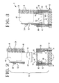
- Figure 4 represents a version of the receptacle connector of the invention showing some six positions for receptacle contact 70.
- the sectioning to the top of the view shows the disposition of the cavity 58 in the lower part of a housing 56 with respect to the various holes 14 in board 12, shown in phantom, and the lower part of the Figure shows the relationship of the engagement between blade and receptacle and contact fingers.
- Figure 4 also shows the bevel 60 which facilitates insertions of plug contacts by guiding such contacts through an engagement with the bevel 44 thereon into the housing 56 and into the receptacles 70.
- Figure 5 shows an alternative version of the housing 56' including features similar to those heretofore described but with the receptacle contact 70' reduced in width along with the housing apertures 58', bevels 60' in relationship to holes 14' of board 12.
- the contacts of Figure 5 include only four posts rather than the six shown in the embodiment with respect to Figure 4.
- the invention contemplates the use of blade and receptacle contacts having either fewer or greater numbers of posts than illustrated with appropriate dimensional changes to the housings. From Figures 4 and 5, it should be appreciated that the invention contemplates uses of the power connector of the invention singly or in multiples with different power connectors utilized for different current circuits or different voltages to include carrying not only power but ground circuits through the boards.
- the power contacts in the invention should be made of high conductivity material, typically a copper alloy, with the receptacle contact having spring characteristics so as to develop adequate normal forces of engagement through the elastic deformation of the fingers 80-82 in engagement with the edges of the blade.
- the invention also contemplates that the advantages herein taught may be achieved through different arrangements of one or more rows of spring fingers defining the receptacle, the positioning of such fingers operating to minimize ramp forces during insertion and to provide redundancy of contact with minimum wear to the blade portion of the power contact.
- the use of the term board is intended to include both rigid and flexible circuits utilized for packaging.
- the present power connector is profile compatible with Z-Pack and offers probe protection by virtue of the toaster cover 56.
- the blades 42 may be of different lengths thereby providing for sequencing.
- the contacts 80,82 are staggered so that each traces a new path along the blade thereby minimizing wear of the blade. This design permits distribution of the power over several points of contact 74 with the board metalization.
Landscapes
- Coupling Device And Connection With Printed Circuit (AREA)
Applications Claiming Priority (2)
| Application Number | Priority Date | Filing Date | Title |
|---|---|---|---|
| US806946 | 1991-12-11 | ||
| US07/806,946 US5158471A (en) | 1991-12-11 | 1991-12-11 | Power connector with current distribution |
Publications (1)
| Publication Number | Publication Date |
|---|---|
| EP0546505A1 true EP0546505A1 (fr) | 1993-06-16 |
Family
ID=25195189
Family Applications (1)
| Application Number | Title | Priority Date | Filing Date |
|---|---|---|---|
| EP92120918A Ceased EP0546505A1 (fr) | 1991-12-11 | 1992-12-08 | Connecteur de puissance à distribution de courant |
Country Status (3)
| Country | Link |
|---|---|
| US (1) | US5158471A (fr) |
| EP (1) | EP0546505A1 (fr) |
| JP (1) | JPH05251125A (fr) |
Cited By (8)
| Publication number | Priority date | Publication date | Assignee | Title |
|---|---|---|---|---|
| WO1996007220A1 (fr) * | 1994-08-29 | 1996-03-07 | The Whitaker Corporation | Raccord electrique a structure de support integree |
| US6089877A (en) * | 1997-06-26 | 2000-07-18 | Siemens Aktiengesellschaft | Plug connector |
| EP1085608A1 (fr) * | 1999-09-17 | 2001-03-21 | TVM Group, Inc. | Connecteur d'alimentation à double contact |
| EP0765004B1 (fr) * | 1995-09-20 | 2001-04-11 | The Whitaker Corporation | Connecteur pour bus d'installation électrique |
| WO2002060013A1 (fr) * | 2001-01-25 | 2002-08-01 | Teradyne, Inc. | Connecteur de puissance du type tranche integree |
| CN1096126C (zh) * | 1994-06-24 | 2002-12-11 | 惠特克公司 | 具有组合支撑结构的电连接器 |
| WO2003085785A1 (fr) * | 2002-03-29 | 2003-10-16 | Teradyne, Inc. | Connecteur de matrice a contacts electriques integres |
| EP3518261A1 (fr) * | 2014-12-16 | 2019-07-31 | Hamilton Sundstrand Corporation | Montage de contacteur intégré, système de distribution de puissance et procédé |
Families Citing this family (65)
| Publication number | Priority date | Publication date | Assignee | Title |
|---|---|---|---|---|
| US5340320A (en) * | 1993-06-25 | 1994-08-23 | The Whitaker Corporation | Shield for a header having right angle electrical terminals |
| US5487673A (en) * | 1993-12-13 | 1996-01-30 | Rockwell International Corporation | Package, socket, and connector for integrated circuit |
| ES1028624Y (es) * | 1994-07-20 | 1995-07-01 | Mecanismos Aux Ind | Hembrilla de potencia perfeccionada. |
| US5591035A (en) * | 1994-10-06 | 1997-01-07 | The Whitaker Corporation | Electrical connector with shortened contact |
| US5630720A (en) * | 1995-03-28 | 1997-05-20 | The Whitaker Corporation | Self polarizing electrical contact |
| US5702257A (en) * | 1996-02-29 | 1997-12-30 | The Whitaker Corporation | Electrical connector and terminal therefor |
| DE19618497A1 (de) * | 1996-05-08 | 1997-11-13 | Amp Holland | Elektrische Verbinderanordnung |
| US5882214A (en) * | 1996-06-28 | 1999-03-16 | The Whitaker Corporation | Electrical connector with contact assembly |
| US7314377B2 (en) * | 1998-04-17 | 2008-01-01 | Fci Americas Technology, Inc. | Electrical power connector |
| US6319075B1 (en) * | 1998-04-17 | 2001-11-20 | Fci Americas Technology, Inc. | Power connector |
| US20020098743A1 (en) * | 1998-04-17 | 2002-07-25 | Schell Mark S. | Power connector |
| US6095821A (en) * | 1998-07-22 | 2000-08-01 | Molex Incorporated | Card edge connector with improved reference terminals |
| US6015299A (en) * | 1998-07-22 | 2000-01-18 | Molex Incorporated | Card edge connector with symmetrical board contacts |
| JP2000251977A (ja) * | 1999-02-26 | 2000-09-14 | Fujitsu Ltd | 電源供給端子 |
| US6123554A (en) * | 1999-05-28 | 2000-09-26 | Berg Technology, Inc. | Connector cover with board stiffener |
| CN1230948C (zh) * | 1999-06-29 | 2005-12-07 | 3M创新有限公司 | 电源及引导连接器 |
| US6315605B1 (en) | 2000-05-09 | 2001-11-13 | Fci Americas Technology, Inc. | Printed circuit board stiffener assembly |
| US6843657B2 (en) | 2001-01-12 | 2005-01-18 | Litton Systems Inc. | High speed, high density interconnect system for differential and single-ended transmission applications |
| US6910897B2 (en) | 2001-01-12 | 2005-06-28 | Litton Systems, Inc. | Interconnection system |
| US6979202B2 (en) | 2001-01-12 | 2005-12-27 | Litton Systems, Inc. | High-speed electrical connector |
| US6394818B1 (en) * | 2001-03-27 | 2002-05-28 | Hon Hai Precision Ind. Co., Ltd. | Power connector |
| JP2003077564A (ja) * | 2001-08-31 | 2003-03-14 | Mitsumi Electric Co Ltd | メモリカード用コネクタ |
| US6716045B2 (en) | 2001-12-10 | 2004-04-06 | Robinson Nugent, Inc. | Connector with increased creepage |
| US6890221B2 (en) * | 2003-01-27 | 2005-05-10 | Fci Americas Technology, Inc. | Power connector with male and female contacts |
| US20040147169A1 (en) | 2003-01-28 | 2004-07-29 | Allison Jeffrey W. | Power connector with safety feature |
| US6780027B2 (en) | 2003-01-28 | 2004-08-24 | Fci Americas Technology, Inc. | Power connector with vertical male AC power contacts |
| US6848950B2 (en) * | 2003-05-23 | 2005-02-01 | Fci Americas Technology, Inc. | Multi-interface power contact and electrical connector including same |
| CN2674672Y (zh) * | 2003-12-06 | 2005-01-26 | 富士康(昆山)电脑接插件有限公司 | 电源连接器 |
| CN2682660Y (zh) * | 2003-12-06 | 2005-03-02 | 富士康(昆山)电脑接插件有限公司 | 电连接器 |
| CN101882718B (zh) * | 2003-12-31 | 2012-11-21 | Fci公司 | 电源触头及包括电源触头的连接器 |
| US6923661B1 (en) | 2004-06-17 | 2005-08-02 | Molex Incorporated | Power connector for mounting on a circuit board |
| CN2728007Y (zh) | 2004-08-05 | 2005-09-21 | 富士康(昆山)电脑接插件有限公司 | 电连接器 |
| JP2006049130A (ja) * | 2004-08-05 | 2006-02-16 | D D K Ltd | 電気コネクタ |
| US20060035488A1 (en) * | 2004-08-12 | 2006-02-16 | International Business Machines Corp. | Connector with conductors exposed to exterior air to facilitate heat removal |
| CN2735587Y (zh) * | 2004-08-17 | 2005-10-19 | 富士康(昆山)电脑接插件有限公司 | 电源连接器 |
| JP2006101603A (ja) * | 2004-09-28 | 2006-04-13 | Sansha Electric Mfg Co Ltd | ラックマウント電源装置の信号線接続構造 |
| US7001189B1 (en) * | 2004-11-04 | 2006-02-21 | Molex Incorporated | Board mounted power connector |
| CN2757374Y (zh) * | 2004-11-18 | 2006-02-08 | 富士康(昆山)电脑接插件有限公司 | 电连接器 |
| US20060128197A1 (en) * | 2004-12-10 | 2006-06-15 | Mcgowan Daniel B | Board mounted power connector |
| US7354282B2 (en) * | 2005-06-15 | 2008-04-08 | Molex Incorporated | Electrical connector having blade terminals |
| JP4834385B2 (ja) * | 2005-11-22 | 2011-12-14 | 株式会社日立製作所 | プリント基板および電子装置 |
| US7376215B2 (en) * | 2005-12-27 | 2008-05-20 | Honeywell International Inc. | Measurement of ash composition using scanning high voltage X-ray sensor |
| US7604489B2 (en) * | 2007-11-13 | 2009-10-20 | Fci Americas Technology, Inc. | μTCA-compliant power contacts |
| US7934961B2 (en) * | 2008-06-11 | 2011-05-03 | Tyco Electronics Corporation | Low profile contact |
| US8092235B2 (en) * | 2008-07-24 | 2012-01-10 | Tyco Electronics Corporation | Connector assembly with grouped contacts |
| USD619099S1 (en) | 2009-01-30 | 2010-07-06 | Fci Americas Technology, Inc. | Electrical connector |
| US8323049B2 (en) | 2009-01-30 | 2012-12-04 | Fci Americas Technology Llc | Electrical connector having power contacts |
| US8403707B2 (en) * | 2010-06-22 | 2013-03-26 | Alltop Electronics (Suzhou) Co., Ltd | Power connector with improved retaining member for being flexibly assembled to power contact |
| CN102299442B (zh) * | 2010-06-22 | 2013-07-10 | 凡甲电子(苏州)有限公司 | 电源连接器 |
| US8262395B2 (en) * | 2010-12-27 | 2012-09-11 | Chief Land Electronic Co., Ltd. | Power connector assembly with improved terminals |
| US8348680B2 (en) | 2011-05-19 | 2013-01-08 | Tyco Electronics Corporation | Daughter card assemblies |
| US8277265B1 (en) * | 2011-06-20 | 2012-10-02 | Tyco Electronics Corporation | Electrical connector for mating in two directions |
| TWM420094U (en) * | 2011-08-26 | 2012-01-01 | Aces Electronic Co Ltd | Plug connector, jack connector and their assembly |
| TWM420093U (en) * | 2011-08-26 | 2012-01-01 | Aces Electronic Co Ltd | Plug connector, jack connector and their assembly |
| TWM420072U (en) * | 2011-08-26 | 2012-01-01 | Aces Electronic Co Ltd | Plug connector, jack connector and their assembly |
| KR101488266B1 (ko) * | 2013-08-06 | 2015-01-30 | 주식회사 유니드 | 착탈형 전기 접속 구조와 이를 구비한 전기 접속용 커넥터, 반도체 패키지 조립체 및 전자기기 |
| US9385500B2 (en) * | 2013-08-26 | 2016-07-05 | FCI Asia Pte. Ltd. | Electrical connector including fins |
| US20150064968A1 (en) * | 2013-08-28 | 2015-03-05 | Tyco Electronics Corporation | Receptacle assembly having a plurality of termination points |
| US9172162B2 (en) * | 2014-02-24 | 2015-10-27 | Tyco Electronics Corporation | Circuit board connector |
| KR101689546B1 (ko) * | 2015-01-22 | 2016-12-26 | 주식회사 유니드 | 착탈형 전기 접속 구조와 이를 구비하는 전자기기 |
| CN206712064U (zh) * | 2017-05-25 | 2017-12-05 | 莫列斯有限公司 | 大电流连接器及大电流连接装置 |
| US11811159B2 (en) | 2020-03-27 | 2023-11-07 | Sung-Yu Chen | Terminal with leaf spring extending rearward from support at both side walls |
| CN214478325U (zh) * | 2020-03-27 | 2021-10-22 | 陈松佑 | 具分流结构的电连接器及分流装置 |
| US12322890B2 (en) * | 2020-06-29 | 2025-06-03 | Microsoft Technology Licensing, Llc | Systems and methods for improving safety on electronic device connections |
| JP2025515525A (ja) * | 2022-05-09 | 2025-05-20 | ヤザキ ノース アメリカ,インコーポレイテッド | 適合ピンアダプタ板 |
Citations (5)
| Publication number | Priority date | Publication date | Assignee | Title |
|---|---|---|---|---|
| CH378967A (de) * | 1960-02-17 | 1964-06-30 | Stin | Löt- und schraubfreie Steckverbindung mit zwei als Steckelemente ausgebildeten elektrischen Leitern |
| FR1371211A (fr) * | 1963-04-23 | 1964-09-04 | Connecteur électrique, plus particulièrement connecteur à fiche | |
| US3183471A (en) * | 1963-02-08 | 1965-05-11 | Thomas & Betts Corp | Electrical terminal and connection |
| DE2428846A1 (de) * | 1974-06-14 | 1976-01-02 | Daut & Rietz Kg | Anordnung zum anbringen von flachen steckerstiften an leiterplatten o.dgl. |
| US4405189A (en) * | 1981-08-13 | 1983-09-20 | Amp Incorporated | Narrow profile power distribution block |
Family Cites Families (4)
| Publication number | Priority date | Publication date | Assignee | Title |
|---|---|---|---|---|
| US4077694A (en) * | 1975-06-24 | 1978-03-07 | Amp Incorporated | Circuit board connector |
| US4241381A (en) * | 1979-04-04 | 1980-12-23 | Amp Incorporated | Bus bar assembly for circuit cards |
| US4755145A (en) * | 1982-11-12 | 1988-07-05 | Teradyne, Inc. | Electrically connecting circuit board system |
| JPS61271765A (ja) * | 1985-05-24 | 1986-12-02 | アムプ インコ−ポレ−テツド | 電気コネクタ |
-
1991
- 1991-12-11 US US07/806,946 patent/US5158471A/en not_active Expired - Fee Related
-
1992
- 1992-12-08 EP EP92120918A patent/EP0546505A1/fr not_active Ceased
- 1992-12-10 JP JP4352206A patent/JPH05251125A/ja active Pending
Patent Citations (5)
| Publication number | Priority date | Publication date | Assignee | Title |
|---|---|---|---|---|
| CH378967A (de) * | 1960-02-17 | 1964-06-30 | Stin | Löt- und schraubfreie Steckverbindung mit zwei als Steckelemente ausgebildeten elektrischen Leitern |
| US3183471A (en) * | 1963-02-08 | 1965-05-11 | Thomas & Betts Corp | Electrical terminal and connection |
| FR1371211A (fr) * | 1963-04-23 | 1964-09-04 | Connecteur électrique, plus particulièrement connecteur à fiche | |
| DE2428846A1 (de) * | 1974-06-14 | 1976-01-02 | Daut & Rietz Kg | Anordnung zum anbringen von flachen steckerstiften an leiterplatten o.dgl. |
| US4405189A (en) * | 1981-08-13 | 1983-09-20 | Amp Incorporated | Narrow profile power distribution block |
Cited By (10)
| Publication number | Priority date | Publication date | Assignee | Title |
|---|---|---|---|---|
| CN1096126C (zh) * | 1994-06-24 | 2002-12-11 | 惠特克公司 | 具有组合支撑结构的电连接器 |
| WO1996007220A1 (fr) * | 1994-08-29 | 1996-03-07 | The Whitaker Corporation | Raccord electrique a structure de support integree |
| EP0765004B1 (fr) * | 1995-09-20 | 2001-04-11 | The Whitaker Corporation | Connecteur pour bus d'installation électrique |
| US6089877A (en) * | 1997-06-26 | 2000-07-18 | Siemens Aktiengesellschaft | Plug connector |
| EP1085608A1 (fr) * | 1999-09-17 | 2001-03-21 | TVM Group, Inc. | Connecteur d'alimentation à double contact |
| US6280245B1 (en) | 1999-09-17 | 2001-08-28 | Tvm Group, Inc. | Dual contact power connector |
| WO2002060013A1 (fr) * | 2001-01-25 | 2002-08-01 | Teradyne, Inc. | Connecteur de puissance du type tranche integree |
| US6592381B2 (en) | 2001-01-25 | 2003-07-15 | Teradyne, Inc. | Waferized power connector |
| WO2003085785A1 (fr) * | 2002-03-29 | 2003-10-16 | Teradyne, Inc. | Connecteur de matrice a contacts electriques integres |
| EP3518261A1 (fr) * | 2014-12-16 | 2019-07-31 | Hamilton Sundstrand Corporation | Montage de contacteur intégré, système de distribution de puissance et procédé |
Also Published As
| Publication number | Publication date |
|---|---|
| JPH05251125A (ja) | 1993-09-28 |
| US5158471A (en) | 1992-10-27 |
Similar Documents
| Publication | Publication Date | Title |
|---|---|---|
| US5158471A (en) | Power connector with current distribution | |
| US5055069A (en) | Connectors with ground structure | |
| US5139426A (en) | Adjunct power connector | |
| EP1939989B1 (fr) | Appareil de connexion | |
| US6592381B2 (en) | Waferized power connector | |
| US6371813B2 (en) | Connector apparatus | |
| EP0520283B1 (fr) | Connecteur avec structure de mise à la masse | |
| EP0460975B1 (fr) | Connecteurs avec structure de mise à la terre | |
| US4867696A (en) | Laminated bus bar with power tabs | |
| US4331370A (en) | Connection system for printed circuit boards | |
| EP1087300B1 (fr) | Ensemble de barre de bus d'ordinateur | |
| US7517240B2 (en) | Fine pitch electrical connector | |
| US4869676A (en) | Connector assembly for use between mother and daughter circuit boards | |
| EP0107288A1 (fr) | Ensemble de connecteur électrique pour terminaison de câble électrique plat blindé | |
| US6290514B1 (en) | Low-inductance low-resistance electrical connector | |
| WO1989002166A1 (fr) | Dispositif de connexion enfichable modulaire permettant une alimentation souple d'appareils electroniques | |
| US6402525B2 (en) | Power connector for connection to a printed circuit board | |
| EP0643449A1 (fr) | Connecteur pour câble-ruban | |
| US5876221A (en) | Surface mount contact assembly for printed circuit board | |
| CN1262049C (zh) | 电连接器组件 |
Legal Events
| Date | Code | Title | Description |
|---|---|---|---|
| PUAI | Public reference made under article 153(3) epc to a published international application that has entered the european phase |
Free format text: ORIGINAL CODE: 0009012 |
|
| AK | Designated contracting states |
Kind code of ref document: A1 Designated state(s): DE FR GB IT NL |
|
| 17P | Request for examination filed |
Effective date: 19931215 |
|
| 17Q | First examination report despatched |
Effective date: 19950420 |
|
| GRAG | Despatch of communication of intention to grant |
Free format text: ORIGINAL CODE: EPIDOS AGRA |
|
| STAA | Information on the status of an ep patent application or granted ep patent |
Free format text: STATUS: THE APPLICATION HAS BEEN REFUSED |
|
| 18R | Application refused |
Effective date: 19960826 |