EP0547037A1 - Procédé et dispositif pour la réalisation d'expérimentation par RMN - Google Patents
Procédé et dispositif pour la réalisation d'expérimentation par RMN Download PDFInfo
- Publication number
- EP0547037A1 EP0547037A1 EP93200416A EP93200416A EP0547037A1 EP 0547037 A1 EP0547037 A1 EP 0547037A1 EP 93200416 A EP93200416 A EP 93200416A EP 93200416 A EP93200416 A EP 93200416A EP 0547037 A1 EP0547037 A1 EP 0547037A1
- Authority
- EP
- European Patent Office
- Prior art keywords
- pulse
- sample
- magnetisation
- sin
- sinusoidal function
- Prior art date
- Legal status (The legal status is an assumption and is not a legal conclusion. Google has not performed a legal analysis and makes no representation as to the accuracy of the status listed.)
- Withdrawn
Links
- 238000000034 method Methods 0.000 title claims abstract description 17
- 238000012565 NMR experiment Methods 0.000 title 1
- 238000005481 NMR spectroscopy Methods 0.000 claims abstract description 14
- 230000000977 initiatory effect Effects 0.000 claims 1
- 230000005855 radiation Effects 0.000 claims 1
- 239000000523 sample Substances 0.000 description 25
- 239000011159 matrix material Substances 0.000 description 13
- XLYOFNOQVPJJNP-UHFFFAOYSA-N water Substances O XLYOFNOQVPJJNP-UHFFFAOYSA-N 0.000 description 8
- 230000004044 response Effects 0.000 description 6
- 230000003595 spectral effect Effects 0.000 description 6
- 238000001727 in vivo Methods 0.000 description 5
- 238000010586 diagram Methods 0.000 description 4
- 230000000694 effects Effects 0.000 description 4
- 230000004807 localization Effects 0.000 description 4
- 229910052709 silver Inorganic materials 0.000 description 4
- 239000004332 silver Substances 0.000 description 4
- 238000001228 spectrum Methods 0.000 description 4
- 239000002131 composite material Substances 0.000 description 3
- 230000005284 excitation Effects 0.000 description 3
- 238000002474 experimental method Methods 0.000 description 3
- 230000035945 sensitivity Effects 0.000 description 3
- 230000008901 benefit Effects 0.000 description 2
- 238000003384 imaging method Methods 0.000 description 2
- 238000001208 nuclear magnetic resonance pulse sequence Methods 0.000 description 2
- 230000000717 retained effect Effects 0.000 description 2
- 238000004611 spectroscopical analysis Methods 0.000 description 2
- 241001465754 Metazoa Species 0.000 description 1
- 230000001447 compensatory effect Effects 0.000 description 1
- 230000008878 coupling Effects 0.000 description 1
- 238000010168 coupling process Methods 0.000 description 1
- 238000005859 coupling reaction Methods 0.000 description 1
- 230000001351 cycling effect Effects 0.000 description 1
- 230000007423 decrease Effects 0.000 description 1
- 230000003247 decreasing effect Effects 0.000 description 1
- 238000001514 detection method Methods 0.000 description 1
- 238000011161 development Methods 0.000 description 1
- 230000005415 magnetization Effects 0.000 description 1
- 230000014759 maintenance of location Effects 0.000 description 1
- 238000005259 measurement Methods 0.000 description 1
- 230000003278 mimic effect Effects 0.000 description 1
- 230000010355 oscillation Effects 0.000 description 1
- 230000001151 other effect Effects 0.000 description 1
- 238000000819 phase cycle Methods 0.000 description 1
- 230000008569 process Effects 0.000 description 1
- 238000001472 pulsed field gradient Methods 0.000 description 1
- 238000011160 research Methods 0.000 description 1
- 241000894007 species Species 0.000 description 1
- 230000001629 suppression Effects 0.000 description 1
- 238000010408 sweeping Methods 0.000 description 1
- 238000012360 testing method Methods 0.000 description 1
- 230000035899 viability Effects 0.000 description 1
Images

Classifications
-
- G—PHYSICS
- G01—MEASURING; TESTING
- G01R—MEASURING ELECTRIC VARIABLES; MEASURING MAGNETIC VARIABLES
- G01R33/00—Arrangements or instruments for measuring magnetic variables
- G01R33/20—Arrangements or instruments for measuring magnetic variables involving magnetic resonance
- G01R33/44—Arrangements or instruments for measuring magnetic variables involving magnetic resonance using nuclear magnetic resonance [NMR]
- G01R33/446—Multifrequency selective RF pulses, e.g. multinuclear acquisition mode
Definitions
- This invention relates to nuclear magnetic resonance (NMR) methods.
- One NMR method makes use of the so called "surface coil” defined herein as a coil which provides an inhomogeneous radio frequency magnetic field.
- the surface coil has proven to be a useful device for irradiation and detection of tissue regions near to the surface of animal or human subjects, particularly for in vivo NMR spectroscopy.
- the gross inhomogeneity of the rf field provided by a surface coil leads to complications. If the surface coil is used to transmit a simple square rf pulse, maximum positive signals will be excited from sample regions where the pulse angle 0 is 90°, no signals can be excited in regions where 0 is 180 °or 360 and maximum negative signals will be generated from regions where 0 is 270 and so on, where signal excitation is given by sin 0.
- the sensitivity of the coil to a sample point is proportional to the pulse angle 0 that can be induced at that point, and so the coil is more sensitive to surface regions closest to it.
- detected signal is proportional to 0 sin 0.
- a further complication is that various signal regions have a complicated shape.
- the sample is excited in a grossly non-uniform manner, but on the other hand only crude localisation of the signal from the sample is achieved, so the surface coil is far from ideal from either point of view.
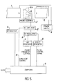
- the apparatus illustrated in Figure 5 comprises a magnet assembly having north and south poles 1 and 2, and a sample support 3, positioned to support the sample, for example a human patient, between the pole pieces 1 and 2.
- the magnet assembly may be a permanent magnet assembly, but is preferably a superconducting electro-magnet, powered by a power supply 4.
- Rf generator 5 is provided to supply an Rf signal to a sample on the sample support, by means of an Rf coil 6.
- the Rf coil 6 is mounted on a probe assembly 7 of conventional form.
- An Rf receiver 8 is connected to a suitable receiving antenna, which may be the coil 6, or may be one or more other coils of conventional form, for example a coil 6a as illustrated schematically in Figure 5.
- the Rf generator 5 and Rf receiver 8 are connected to a computer 9, programmed and arranged to control the phase and frequency of Rf signals produced by the Rf generator 5, and to receive signals from the Rf receiver 8 and process them as indicated herein, in order to obtain the desired NMR signal.
- a pulse generator 10 is also controlled by computer 9.
- the output from the pulse generator 10 is fed to an Rf modulator 11, which modulates the Rf signal produced by the Rf generator 5, thereby to produce the desired sequence of Rf pulses.
- the sequence of Rf pulses is amplified by Rf amplifier 12, which not only controls the overall amplitude of Rf pulse signals fed to the probe assembly 7, but also, by means of control link 13, can control the relative amplitudes of indivdual Rf pulses, under the control of the computer 9.
- the computer 9 is so programmed and arranged as to produce the desired pulse range, as disclosed herein, according to methods which are generally known per se.
- the diagram illustrates magnetisation component spin-locked AH (Hz) off-resonance by the effective field B at an angle a to the transverse plane of the rotating frame.
- AH spin-locked AH
- the spin-locked component will be sin a times the initial z magnetisation. If AH is then reduced to zero adiabatically the spin-locked component follows B down to the x axis and may be detected.
- the spin-locked magnetisation component is at an angle a to the transverse plane and aligned with the effective field B, where a and B are given by
- the spin-lock pulse is switched on in the presence of the field gradient, then at sample points where ⁇ H>B 1 , the initial angle a is large and most of the initial z magnetisation would be spin-locked along B.
- this spin-locked component would be rotated down to the transverse plane and could be detected after switching off the rf pulse - this is known as "half adiabatic passage" in traditional NMR spectroscopy (Ref 4). If the field gradient is perpendicular to the surface coil with the zero-crossing plane of the gradient aligned with the sample surface, then the initial AH is small and B 1 is large at the sample surface.
- the initial angle a is small and little of the initial z magnetisation would be spin-locked at the sample surface.
- a large proportion of maximum possible signal could be detected from moderate depths into the sample, with suppression of surface signals, a crude but potentially useful form of sample localisation.
- the length of the spin-lock pulse on either side of the gradient switching point needs to be randomised over a series of transients to eliminate any residual un-locked magnetisation not dephased by the switched gradient (Ref 3).
- the most efficient mathematical form of the time profile of the gradient switching to obey inequality (2) also needs to be established before the conditions of practical viability of this method are known.
- the amplitude of the rf pulse may be increased from zero as its frequency is swept onto resonance.
- the exact form of this amplitude/frequency modulation is determined by the need to obtain maximum efficiency with respect to inequality (2).
- the component of magnetisation still aligned with z (ie. B) at the end of the pulse is given by the f zz term of matrix (11) described in M. R. Bendall and D. T. Pegg, Magn. Reson. Med. 2, 91 (1985) (Ref 5), with a' and ⁇ " in place of a and 0', which is This is the component which can be considered to have "followed" the rotating B field down to the y axis of Fig. 1, or undergone half adiabatic passage.
- the final y component is more than 90% of the initial z magnetisation for A/v>3 (ie
- a suitable rotation matrix such as matrix (11) of Ref (5).
- phase modulation was used instead. Since phase is the integral of frequency, the phase was modulated as (A/2 ⁇ v) sin 2 ⁇ vt using 256 pulse increments.
- An obvious first demonstration utilized a small water phantom at the centre of a larger surface coil. The sin/cos pulse induced a similar signal response to that provided by a 90 square pulse, and the phase and amplitude of the signal was remarkably insensitive to changing the transmitter pulse power.
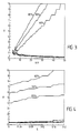
- Figure 2 shows one-dimensional images of the signal response from a column of water placed perpendicularly on top of the surface call wire.
- the figure illustrates signal responses as a function of distance in the xy plane from a 7 cm diameter surface coil for a 12.5 cm long perpendicular column of water, for square pulses (continuous curves numbered 1 to 11) and for the sin/cos pulse (dashed curve).
- the square pulse lengths were 40, 50, 70, 100, 133, 160, 200, 250, 300, 400 and 500 us respectively.
- the maximum possible signal decreases with distance from the coil in accordance with the decreasing sensitivity of the coil to remote samples.
- the square pulses (of x phase) and the sin/cos pulses were followed by a 25ms spin-lock pulse of y phase, during the central 5 ms of which a read-out gradient was switched on.
- the read-out gradient was weak (60 Hz/cm) and the zero-crossing point was near the remote end of the water column so that signal loss from off-resonance effects in the gradient was less than 2%.
- the long spin-lock pulse ensured that any unlocked components were efficiently dephased.
- Figure 2 also illustrates the interference that must be generated between positive and negative signals, resulting in signal loss, when using long square pulses to sample increased depths, and that this is avoided by use of the sin/cos pulse.
- the sin/cos pulse should be useful in maximising signal-to-noise in in vivo spectroscopy in situations where localisation beyond that determined by the sensitivity of the surface coil is not required.
- the importance of maximising S/N using complex pulses has been recognised (M. S. Silver, R.I. Joseph and D. I. Hoult, J. Magn. Reson. 59, 347 (1984) (Ref 7)).
- There may also be applications in high-resolution NMR since the pulse is superior to the best available 90 composite pulse R. Tycko, H.M. Cho, E. Schneider and A. Pines, J. Magn. Reson. 61 90 (1985) (Ref 6)).
- other pulses such as one half of the sech/tanh pulse of Silver et al may be used.
- the adiabatic 90 excitation pulse described can readily excite more than 90% of possible NMR signal across a factor of 10 variation in rf field strength and over a reasonable spectral width.
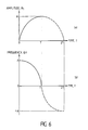
- This rf pulse is an amplitude/frequency modulated pulse called a "sin/cos" pulse during which the amplitude and frequency are modulated as one quarter of a complete cycle of sine and cosine functions respectively.
- Doubling the length of the pulse to one half of complete sine and cosine cycles generates a 180 inversion pulse which is similarly insensitive to variation in the B 1 field and is related to the sech/tanh inversion pulse of Silver et al (Ref 7).
- the sin/cos 180 inversion pulse is useful over a reasonable spectral width, or it may be utilised in a pulsed field gradient for slice selection in imaging or localised spectroscopy.
- Our calculations indicate that the sin/cos 180 ° pulse has an advantage in length and sometimes maximum required rf power over the equivalent sech/tanh pulse for these applications.
- a 180 inversion pulse could also function as a 180° refocusing pulse especially since it can be readily shown that for any pulse the proportion of z magnetisation that is inverted is exactly equivalent to the proportion of transverse magnetisation that is refocused (M. R. Bendall and D. T. Pegg, J. Magn Reson. 63 494 (1985)(Ref 8)).
- the phase of the refocused magnetisation be constant under the relevant variable conditions which in our case are variable B 1 and variable resonance offset AH.
- both the sin/cos and sech/tanh 180 °pulses generate refocused magnetisation with widely varying phase depending on the magnitude of Bi. We show below that this phase problem can be eliminated or reduced by inverting the effective field, B, halfway through the pulse. We signify these "B flips" by (+-) added to our previous nomenclature, eg. sin/cos(+-).
- f xx , fy x f x y and fyy are of course the individual components of x and y magnetisation resulting from unit x or y magnetisation prior to the pulse as expressed by These terms may be calculated for any complex pulse by splitting it into a sufficiently large number (1000 increments or greater) of successive square pulses with corresponding successive application of the Bloch equations. Alternatively and equivalently, the effect of the successive pulse increments can be calculated by successive application of matrix (8). Generally the phase is constant (zero) except at the B flip where it is inverted (180° ).
- a refocusing pulse is one which inverts x magnetisation but retains y magnetisation (or vice versa).
- x magnetisation will be spin locked by the initial conditions of large B 1 on-resonance and remain spin locked as the effective field rotates up to the z axis midway through the pulse and then down to the -x axis, ie. x magnetisation is cleanly inverted.
- a pulse must also invert z magnetisation, ie. it must rotate a plane of spins 180° around the y axis.
- any good 180° plane rotation pulse we know that the sin/cos 180 ° pulse inverts z magnetisation, and this property will be retained by including a B flip as in the sin/cos (+-) pulse, ie. the pulse is described by
- the refocused component is more than 90% of initial transverse magnetisation for A/v >4 and more than 95% for A/v>7, and there are no phase problems. Note that if the initial rf has y phase, x magnetisation is restrained and y magnetisation is inverted by the sin/cos (+ -) pulse.
- a complex refocusing pulse is only suitable for practical application if it can be used under variable conditions of rf power across a reasonable spectral width.
- S the frequency offset of a nucleus from the centre of the spectrum
- v allows for variation of B 1 because of rf homogeneity or experimental misetting.
- Figure 3 is a contour plot of the magnitude of the refocussed component versus the variables v and A/v.
- the excellent phase properties of the pulse are retained for variable B 1 with no significant phase variation ( «1 °) for the ranges of A/v and v shown in Figure 3.
- the on-resonance 90 pulse time for a square pulse provided by a surface coil is 100 ⁇ s at the centre of a region of interest then a 5.7 ms sin/cos (+ -) pulse will refocus more than 90% of all transverse magnetization across a factor of 8 variation of the B 1 field around this region centre, and across a spectral width of ⁇ 350Hz.
- introduction of the effective field (B) flip satisfactorily eliminates the potential phase problem which otherwise prevents the use of adiabatic pulses as refocusing pulses, but retains the insensitivity of the pulse to rf inhomogenity.
- the sech/tanh 180° inversion pulse of Silver et al may also be converted to a refocusing pulse by inclusion of a B flip as in sech/tanh (+-).
- our preliminary calculations indicate that the sin/cos (+ -) pulse has an advantage in terms of the length of the pulse needed to achieve the same purpose.
- Figure 6 shows an example radiofrequency pulse sequence.
- a sin/cos radiofrequency pulse the amplitude of the radiofrequency signal is modulated as a sine function (a), and the frequency of the radiofrequency signal is concurrently modulated as a cosine function (b).
- b the frequency of the radiofrequency signal
Landscapes
- Physics & Mathematics (AREA)
- High Energy & Nuclear Physics (AREA)
- Condensed Matter Physics & Semiconductors (AREA)
- General Physics & Mathematics (AREA)
- Magnetic Resonance Imaging Apparatus (AREA)
Priority Applications (1)
| Application Number | Priority Date | Filing Date | Title |
|---|---|---|---|
| EP93200416A EP0547037A1 (fr) | 1985-11-20 | 1986-11-20 | Procédé et dispositif pour la réalisation d'expérimentation par RMN |
Applications Claiming Priority (3)
| Application Number | Priority Date | Filing Date | Title |
|---|---|---|---|
| GB8528551 | 1985-11-20 | ||
| GB858528551A GB8528551D0 (en) | 1985-11-20 | 1985-11-20 | Performing n m r experiment |
| EP93200416A EP0547037A1 (fr) | 1985-11-20 | 1986-11-20 | Procédé et dispositif pour la réalisation d'expérimentation par RMN |
Related Parent Applications (1)
| Application Number | Title | Priority Date | Filing Date |
|---|---|---|---|
| EP86906727.2 Division | 1986-11-20 |
Publications (1)
| Publication Number | Publication Date |
|---|---|
| EP0547037A1 true EP0547037A1 (fr) | 1993-06-16 |
Family
ID=26133658
Family Applications (1)
| Application Number | Title | Priority Date | Filing Date |
|---|---|---|---|
| EP93200416A Withdrawn EP0547037A1 (fr) | 1985-11-20 | 1986-11-20 | Procédé et dispositif pour la réalisation d'expérimentation par RMN |
Country Status (1)
| Country | Link |
|---|---|
| EP (1) | EP0547037A1 (fr) |
-
1986
- 1986-11-20 EP EP93200416A patent/EP0547037A1/fr not_active Withdrawn
Non-Patent Citations (2)
| Title |
|---|
| JOURNAL OF MAGNETIC RESONANCE vol. 59, 1984, ORLANDO, MN US pages 347 - 351 M.S.SILVER & AL 'HIGHLY SELECTIVE ..' * |
| JOURNAL OF MAGNETIC RESONANCE vol. 59, 1984, ORLANDO, MN US pages 406 406 - 429 M.R.BENDALL 'ELIMINATION OF HIGH-FLUX SIGNALS NEAR SURFACE COILS AND FIELD GRADIENT SAMPLE LOCALIZATION USING DEPTH PULSES' CHAPTER :INTRODUCTION AND CONCLUSION * |
Similar Documents
| Publication | Publication Date | Title |
|---|---|---|
| EP0248039B1 (fr) | Mesure de la resonance magnetique nucleaire (rnm) par regulation du champ magnetique effectif | |
| EP0086972B2 (fr) | Méthode de formation d'images à RMN surmontant les effets T2* dans un champ magnétique statique non-homogène | |
| US4297637A (en) | Method and apparatus for mapping lines of nuclear density within an object using nuclear magnetic resonance | |
| US4318043A (en) | Method and apparatus for rapid NMR imaging of nuclear densities within an object | |
| Fram et al. | Rapid calculation of T1 using variable flip angle gradient refocused imaging | |
| US4254778A (en) | Imaging systems | |
| EP0091008B1 (fr) | Méthode de formation d'image RMN en trois dimensions utilisant une excitation sélective | |
| US4999580A (en) | magnetic resonance imaging and spectroscopy using a single excitation pulse for simultaneous spatial and spectral selectivity | |
| US5019784A (en) | Time symmetric pulse to uniformly rotate magnetization vectors by an arbitrary angle in the presence of large B1 inhomogeneities and resonance offsets | |
| Talagala et al. | Introduction to magnetic resonance imaging | |
| Conolly et al. | A selective adiabatic spin-echo pulse | |
| US6452387B1 (en) | Catalyzing the transient response in steady-state MRI sequences | |
| Garwood et al. | Magnetic resonance imaging with adiabatic pulses using a single surface coil for RF transmission and signal detection | |
| US4985677A (en) | Magnetic resonance imaging and spectroscopy using an excitation pulse for multiple-dimensional selectivity | |
| Bendall | Elimination of high-flux signals near surface coils and field gradient sample localization using depth pulses | |
| US5189371A (en) | Method and means for magnetic resonance imaging and spectroscopy using two-dimensional selective adiabatic PI pulses | |
| US4654591A (en) | NMR flow imaging using bi-phasic excitation field gradients | |
| US4803432A (en) | Short echo NMR imaging of sodium | |
| De Graaf et al. | Single‐shot, B1‐insensitive slice selection with a gradient‐modulated adiabatic pulse, BISS‐8 | |
| CA2004007C (fr) | Methodes de saisie de signaux de resonance magnetique | |
| EP0478632B1 (fr) | Methodes d'imagerie par resonance magnetique nucleaire | |
| US4914392A (en) | Amplitude and frequency/phase modulated pulses to achieve plane rotations of nuclear spin magnetization vectors with inhomogeneous B1 | |
| Conolly et al. | Sweep-diagram analysis of selective adiabatic pulses | |
| EP0259998B1 (fr) | Procédés d'imagerie de solides par des techniques RMN | |
| US4743850A (en) | Method of mapping the nuclear magnetic properties of an object to be examined |
Legal Events
| Date | Code | Title | Description |
|---|---|---|---|
| PUAI | Public reference made under article 153(3) epc to a published international application that has entered the european phase |
Free format text: ORIGINAL CODE: 0009012 |
|
| 17P | Request for examination filed |
Effective date: 19930222 |
|
| AC | Divisional application: reference to earlier application |
Ref document number: 248039 Country of ref document: EP |
|
| AK | Designated contracting states |
Kind code of ref document: A1 Designated state(s): CH DE FR GB LI NL |
|
| 17Q | First examination report despatched |
Effective date: 19941216 |
|
| GRAH | Despatch of communication of intention to grant a patent |
Free format text: ORIGINAL CODE: EPIDOS IGRA |
|
| STAA | Information on the status of an ep patent application or granted ep patent |
Free format text: STATUS: THE APPLICATION IS DEEMED TO BE WITHDRAWN |
|
| 18D | Application deemed to be withdrawn |
Effective date: 19960326 |