EP0547264A1 - Dispositif de sécurité pour commande d'une boîte de vitesses de véhicule automobile - Google Patents
Dispositif de sécurité pour commande d'une boîte de vitesses de véhicule automobile Download PDFInfo
- Publication number
- EP0547264A1 EP0547264A1 EP91121777A EP91121777A EP0547264A1 EP 0547264 A1 EP0547264 A1 EP 0547264A1 EP 91121777 A EP91121777 A EP 91121777A EP 91121777 A EP91121777 A EP 91121777A EP 0547264 A1 EP0547264 A1 EP 0547264A1
- Authority
- EP
- European Patent Office
- Prior art keywords
- locking
- selector
- gearbox
- rods
- dowels
- Prior art date
- Legal status (The legal status is an assumption and is not a legal conclusion. Google has not performed a legal analysis and makes no representation as to the accuracy of the status listed.)
- Withdrawn
Links
- 230000007935 neutral effect Effects 0.000 claims abstract description 27
- 230000008878 coupling Effects 0.000 claims abstract description 13
- 238000010168 coupling process Methods 0.000 claims abstract description 13
- 238000005859 coupling reaction Methods 0.000 claims abstract description 13
- 230000000717 retained effect Effects 0.000 claims description 2
- 230000007704 transition Effects 0.000 claims description 2
- 238000006073 displacement reaction Methods 0.000 abstract description 2
- 238000004519 manufacturing process Methods 0.000 description 3
- 238000010276 construction Methods 0.000 description 1
- 239000007787 solid Substances 0.000 description 1
Images

Classifications
-
- F—MECHANICAL ENGINEERING; LIGHTING; HEATING; WEAPONS; BLASTING
- F16—ENGINEERING ELEMENTS AND UNITS; GENERAL MEASURES FOR PRODUCING AND MAINTAINING EFFECTIVE FUNCTIONING OF MACHINES OR INSTALLATIONS; THERMAL INSULATION IN GENERAL
- F16H—GEARING
- F16H63/00—Control outputs from the control unit to change-speed- or reversing-gearings for conveying rotary motion or to other devices than the final output mechanism
- F16H63/02—Final output mechanisms therefor; Actuating means for the final output mechanisms
- F16H63/30—Constructional features of the final output mechanisms
- F16H63/34—Locking or disabling mechanisms
- F16H63/36—Interlocking devices
Definitions
- the present invention relates to a safety device for a motor vehicle gearbox of the type comprising a first shaft carrying a first series of gears connected for rotation with it, and a second shaft carrying a second series of gears which are freely rotatably mounted on the said second shaft and which are in constant mesh with respective gears of the first shaft, and a plurality of coupling devices for connecting respective gears of the said second series for rotation with the said second shaft.
- the invention relates in particular to a safety device for a motor vehicle gearbox control, of the type comprising a plurality of selector rods slidable parallel to one another in the casing of the gearbox and each carrying at least one fork member for controlling a respective coupling device, each selector rod being displaceable between a neutral position and at least one operative position, and locking means for locking, with respect to the gearbox casing, all the selector rods with the exception of that which is selected at the time, the said locking means including a series of locking dowels slidable in respective seats in the gearbox casing and having active ends adapted to cooperate with respective reference notches provided on the selector rods when these are in their neutral positions so that, when a selector rod is moved away from its neutral position, the other selector rods are retained in their neutral positions by the engagement of the said locking dowels in the respective reference notches.
- a control device of the type indicated above is, for example, described and illustrated in European Patent EP-B-0170630.
- the axes of the selector rods are disposed in the same plane. This involves the necessity of providing the various selector rods with fork members of different shapes and dimensions, the distance from the axis of each selector rod to the axis of the shaft with which the coupling devices are associated being different from that of the other selector rods.
- the present invention provides a control device of the aforesaid type, characterized by the combination of the following characteristics:
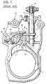
- Figure 1 is a sectional view on a plane perpendicular to the axes of the gearbox shafts.
- the gearbox comprises a series of pairs of constantly meshing gears (not illustrated) and coupling devices (also not illustrated) for controlling the engagement of the various gear ratios.
- Each pair of gears is constituted by a gear connected for rotation with a first shaft of the gearbox and a gear mounted freely rotatably on a second shaft of the gearbox, this latter being moreover provided with an associated coupling device for connecting the freely rotatable gear for rotation with the second shaft of the gearbox.
- the said arrangement can be made in different ways.
- the synchroniser devices can be associated with the so-called primary shaft of the gearbox, that is to say the shaft which is driven by the drive shaft via the clutch, or with the secondary shaft, or even some with the primary shaft and some with the secondary shaft.
- This detail lies outside the ambit of the present invention, which is applicable to any possible gearbox configuration. For this reason, and for reasons of simplicity and clarity, the said details have not been illustrated in the attached drawings.
- the coupling devices which control the engagement of the various gear ratios are controlled, in a manner known per se, by means of fork members one of which is indicated with the reference numeral 1 in Figure 1.
- the fork 1 has a boss 1a fixed to a selector rod 2 which is slidable in the casing 3 of the gearbox.
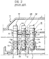
- the rod 2 has a neutral position which has been illustrated in solid outline in Figure 2, and two operative end positions (illustrated in broken outlines in Figure 2) corresponding to the respective engagement of first and second gear.
- the rod 2 is moreover provided with three notches 2a, 2b, 2c intended to cooperate with a ball or like member (not illustrated) resiliently thrust against the rod 2 in order to snap engage this rod in each of the said three positions.
- the boss 1a of the fork 1 which is fixed to the rod 2 is provided with a projection 3 having a slot 3a which can receive a finger 4 projecting radially from a control shaft 5 rotatably mounted about its geometric axis 6 in the gearbox casing 10.
- the shaft 5 is also slidable axially in the casing 10 and is biased by springs 7 towards the neutral position which is illustrated in Figure 1.
- the finger 4 is received in the slot 8 of a nose 9 having a boss 11 fixed to a selector rod 12 which is slidable in the gearbox casing 10 along an axis parallel to the axis of the rod 2 and which is intended to control (by means of a fork member not visible in the drawings) the coupling device for engaging third and fourth gears.
- the rod 12 has a neutral position and two operative end positions ( Figure 2), the said three positions being defined by the engagement of a ball or like member (not illustrated),resiliently urged against the rod 12 in one of three notches 12a, 12b, 12c with which the rod 12 is provided.
- the known device illustrated in Figures 1 and 2 includes a third rod 13, slidable in the gearbox casing 10, on which there is fixed a boss 14 forming part of a nose-like projection 15 the free end of which has a slot 16 adapted to cooperate with the finger 4.
- the rod 13 also has two operative end positions corresponding to the engagement of fifth gear and reverse gear, and a central neutral position.
- the axes of the three selector rods 2, 12, 13 are disposed in a single plane. It follows that the distances from the axes of these rods to the axis 17 of the shaft carrying the synchroniser devices differ and consequently the dimensions and shape of the associated fork members mounted on the rods are different.
- the prior art gearbox further includes locking means, generally indicated with the reference numeral 18, such that when one of the selector rods is moved away from its neutral position the other selector rods remain locked in the neutral position with respect to the gearbox casing.
- locking means generally indicated with the reference numeral 18, such that when one of the selector rods is moved away from its neutral position the other selector rods remain locked in the neutral position with respect to the gearbox casing.
- this is obtained by providing within the gearbox casing two coaxial cylindrical seats 19 extending transversely of the axes of the rods 2, 12, 13, within which are slidable locking dowels 20 having active ends adapted to cooperate with respective reference notches provided in the rods 2, 12, 13.
- the rod 12 is also provided with a transverse through hole within which a further, auxiliary locking dowel 21 is slidable mounted, which is interposed between the two locking dowels 20.
- the arrangement is such that when one of the rods is moved away from its neutral position the train constituted by the two principal locking dowels 20 and the auxiliary dowel 21 is displaced such that the two locking dowels 20 come into engagement with respective reference notches provided on the two non-actuated selector rods thereby locking these latter with respect to the gearbox casing.
- Figure 3 illustrates a gearbox according to the invention.
- the gearbox is provided with four selector rods 30, 31, 32, 33.
- the selector rod 30 controls engagement of second and third gear.
- the selector rod 31 controls engagement of fourth and fifth gear.
- the selector rod 32 controls engagement of sixth and seventh gear, whilst the selector rod 33 controls engagement of first and reverse gears.
- the axes 30a, 31a, 32a, 33a of the said selector rods are disposed at the same distance from the axis 17 of the gearbox shaft with which the coupling devices are associated. This makes it possible for the selector rods to have associated fork members of the same shape and dimensions, with the advantage of facilitating manufacture, assembly and storage of the components of the gearbox of the invention.
- the device of the invention guarantees that when one of the selector rods is moved away from its neutral position the other selector rods can be displaced only by an insignificant distance which in any event is such as to maintain the other gear ratios in neutral position.
- the locking means 18 comprise four main locking dowels 34 which are slidable in cylindrical holes 35 disposed on separate substantially parallel axes.
- Each main locking dowel 34 has an active end which cooperates with a respective reference notch 30b, 31b, 32b, 33b formed in the respective selector rod.
- the ends of the seats 35 opposite the active ends of the main locking dowels 34 open into a common cylindrical cavity 36 formed in the gearbox casing 10 and extending transversely with respect to the seats 35.
- a train of locking pins 37 In the transverse cylindrical cavity 36 there is arranged a train of locking pins 37.
- auxiliary pins 41 acted on by two coil springs 38 each having an end in engagement with the respective pin 41 and an opposite end in engagement with an associated closure plug 39 screwed into a larger diameter threaded end portion 40 of the cylindrical cavity 36.
- the springs 38 bias the auxiliary pins 41 into engagement with a shoulder 42 formed at the bottom of the seat 40.
- the system is designed such that, when the gearbox is in neutral position the two auxiliary pins 41 maintain the locking pins 37 in a centred position in which engagement of any gear is permitted.
- the associated reference notch comes out of engagement with the associated locking dowel 34 and therefore causes this locking dowel 34 to project into the transverse cylindrical cavity 36.
- the train of auxiliary locking pins 37 is arranged in such a way that, when all the rods 30, 31, 32, 33 are in their neutral positions, the respective locking dowels 34 face the transition zone between one locking pin 37 and the adjacent pin. Therefore, when the movement of a selector rod causes the respective locking dowel 34 to project into the cavity 36, the said locking dowel 34 is interposed between two adjacent locking pins 37 thereby constraining the said locking pins 37 to obstruct the exits from the seats 35 associated with the other selector rods. These latter, therefore, are not free to move away from their neutral positions since the associated locking dowels 34 cannot project into the common transverse cavity 36.
- the device of the invention is naturally applicable to any type of gearbox, whatever the particular configuration of the gearbox or whether the gearbox is of conventional type with lever control or provided with actuator means for servo control of the selector rods.
Landscapes
- Engineering & Computer Science (AREA)
- General Engineering & Computer Science (AREA)
- Mechanical Engineering (AREA)
- Gear-Shifting Mechanisms (AREA)
Priority Applications (1)
| Application Number | Priority Date | Filing Date | Title |
|---|---|---|---|
| EP91121777A EP0547264A1 (fr) | 1991-12-19 | 1991-12-19 | Dispositif de sécurité pour commande d'une boîte de vitesses de véhicule automobile |
Applications Claiming Priority (1)
| Application Number | Priority Date | Filing Date | Title |
|---|---|---|---|
| EP91121777A EP0547264A1 (fr) | 1991-12-19 | 1991-12-19 | Dispositif de sécurité pour commande d'une boîte de vitesses de véhicule automobile |
Publications (1)
| Publication Number | Publication Date |
|---|---|
| EP0547264A1 true EP0547264A1 (fr) | 1993-06-23 |
Family
ID=8207448
Family Applications (1)
| Application Number | Title | Priority Date | Filing Date |
|---|---|---|---|
| EP91121777A Withdrawn EP0547264A1 (fr) | 1991-12-19 | 1991-12-19 | Dispositif de sécurité pour commande d'une boîte de vitesses de véhicule automobile |
Country Status (1)
| Country | Link |
|---|---|
| EP (1) | EP0547264A1 (fr) |
Cited By (1)
| Publication number | Priority date | Publication date | Assignee | Title |
|---|---|---|---|---|
| EP1602863A1 (fr) * | 2004-06-05 | 2005-12-07 | Zf Friedrichshafen Ag | Dispositif de blocage et déverrouillage pour tringles de changement d'une boite de vitesses |
Citations (4)
| Publication number | Priority date | Publication date | Assignee | Title |
|---|---|---|---|---|
| DE1016997B (de) * | 1954-11-06 | 1957-10-03 | Opel Adam Ag | Verriegelungs- und Rastanordnung mehrere Schaltstangen fuer Zahnraederwechselgetriebe |
| US3115047A (en) * | 1960-08-08 | 1963-12-24 | Ford Motor Co | Synchronized multiple speed power transmission mechanism |
| US3242759A (en) * | 1963-06-28 | 1966-03-29 | Zahnradfabrik Friedrichshafen | Shifting arrangement for change speed gears of motor vehicles |
| EP0170630A1 (fr) * | 1984-07-11 | 1986-02-05 | FIAT AUTO S.p.A. | Dispositif de commande d'une boîte de vitesses pour des véhicules à moteur |
-
1991
- 1991-12-19 EP EP91121777A patent/EP0547264A1/fr not_active Withdrawn
Patent Citations (4)
| Publication number | Priority date | Publication date | Assignee | Title |
|---|---|---|---|---|
| DE1016997B (de) * | 1954-11-06 | 1957-10-03 | Opel Adam Ag | Verriegelungs- und Rastanordnung mehrere Schaltstangen fuer Zahnraederwechselgetriebe |
| US3115047A (en) * | 1960-08-08 | 1963-12-24 | Ford Motor Co | Synchronized multiple speed power transmission mechanism |
| US3242759A (en) * | 1963-06-28 | 1966-03-29 | Zahnradfabrik Friedrichshafen | Shifting arrangement for change speed gears of motor vehicles |
| EP0170630A1 (fr) * | 1984-07-11 | 1986-02-05 | FIAT AUTO S.p.A. | Dispositif de commande d'une boîte de vitesses pour des véhicules à moteur |
Cited By (1)
| Publication number | Priority date | Publication date | Assignee | Title |
|---|---|---|---|---|
| EP1602863A1 (fr) * | 2004-06-05 | 2005-12-07 | Zf Friedrichshafen Ag | Dispositif de blocage et déverrouillage pour tringles de changement d'une boite de vitesses |
Similar Documents
| Publication | Publication Date | Title |
|---|---|---|
| US5743147A (en) | Gear shift device | |
| US4275612A (en) | Shift control for change speed gear transmission for vehicle | |
| EP0131720A1 (fr) | Dispositif de sélection et d'engagement des vitesses pour une transmission de véhicule à moteur | |
| US5272931A (en) | Transmission shift control mechanism | |
| US3933057A (en) | Automotive vehicle shift control mechanism for manual transmissions | |
| US2953035A (en) | Gear shift interlock and detent mechanism | |
| US5191806A (en) | Safety interlock device for a motor vehicle gearbox control | |
| US3452614A (en) | Shift lever mechanism with shift rail interlock and stop means | |
| EP0478029A2 (fr) | Mécanisme de commande d'une boîte de changement de vitesses manuelle | |
| EP0547264A1 (fr) | Dispositif de sécurité pour commande d'une boîte de vitesses de véhicule automobile | |
| US3527116A (en) | Transmission control | |
| EP0149020A2 (fr) | Dispositifs pour le changement de vitesse et pour la commande d'une transmission en particulier pour véhicules industriels | |
| EP0170630B1 (fr) | Dispositif de commande d'une boîte de vitesses pour des véhicules à moteur | |
| US3016759A (en) | Gear shift lock | |
| EP1468211B1 (fr) | Systeme de cassette de changement de vitesse | |
| EP0849508B1 (fr) | Dispositif de commande d'une boíte de vitesses de véhicule | |
| EP1009942A2 (fr) | Dispositif de commande pour variateur de vitesse | |
| US5203225A (en) | Vehicle transmission gearshift for preventing accidental engagement | |
| US2775901A (en) | Shift actuated control device | |
| US4648283A (en) | Gear shift control mechanism | |
| JPH05215236A (ja) | 車両用変速機制御装置の安全装置 | |
| JPS5860329A (ja) | 自動車の変速装置 | |
| EP0443992A1 (fr) | Commande de la boîte de vitesse d'un véhicule, plus particulièrement pour des tracteurs agricoles | |
| US3367204A (en) | Gear selector mechanism | |
| US3258986A (en) | Shift selector mechanism for manually controlled transmission mechanism |
Legal Events
| Date | Code | Title | Description |
|---|---|---|---|
| PUAI | Public reference made under article 153(3) epc to a published international application that has entered the european phase |
Free format text: ORIGINAL CODE: 0009012 |
|
| AK | Designated contracting states |
Kind code of ref document: A1 Designated state(s): AT BE CH DE DK ES FR GB GR IT LI LU NL SE |
|
| STAA | Information on the status of an ep patent application or granted ep patent |
Free format text: STATUS: THE APPLICATION IS DEEMED TO BE WITHDRAWN |
|
| 18D | Application deemed to be withdrawn |
Effective date: 19931224 |