EP0547323A1 - Dispositif de branchement des guides d'ondes lumineuses - Google Patents
Dispositif de branchement des guides d'ondes lumineuses Download PDFInfo
- Publication number
- EP0547323A1 EP0547323A1 EP92117494A EP92117494A EP0547323A1 EP 0547323 A1 EP0547323 A1 EP 0547323A1 EP 92117494 A EP92117494 A EP 92117494A EP 92117494 A EP92117494 A EP 92117494A EP 0547323 A1 EP0547323 A1 EP 0547323A1
- Authority
- EP
- European Patent Office
- Prior art keywords
- cable
- branch
- tap
- branching device
- subscriber
- Prior art date
- Legal status (The legal status is an assumption and is not a legal conclusion. Google has not performed a legal analysis and makes no representation as to the accuracy of the status listed.)
- Granted
Links
- 239000000835 fiber Substances 0.000 claims description 13
- 239000013307 optical fiber Substances 0.000 claims description 9
- 230000003287 optical effect Effects 0.000 abstract description 4
- 230000008901 benefit Effects 0.000 description 5
- 238000010276 construction Methods 0.000 description 4
- 238000000034 method Methods 0.000 description 2
- RYGMFSIKBFXOCR-UHFFFAOYSA-N Copper Chemical compound [Cu] RYGMFSIKBFXOCR-UHFFFAOYSA-N 0.000 description 1
- 238000009412 basement excavation Methods 0.000 description 1
- 238000004891 communication Methods 0.000 description 1
- 229910052802 copper Inorganic materials 0.000 description 1
- 239000010949 copper Substances 0.000 description 1
- 238000005516 engineering process Methods 0.000 description 1
- 239000003365 glass fiber Substances 0.000 description 1
- 238000009434 installation Methods 0.000 description 1
Images
Classifications
-
- G—PHYSICS
- G02—OPTICS
- G02B—OPTICAL ELEMENTS, SYSTEMS OR APPARATUS
- G02B6/00—Light guides; Structural details of arrangements comprising light guides and other optical elements, e.g. couplings
- G02B6/24—Coupling light guides
- G02B6/36—Mechanical coupling means
- G02B6/38—Mechanical coupling means having fibre to fibre mating means
- G02B6/3801—Permanent connections, i.e. wherein fibres are kept aligned by mechanical means
-
- G—PHYSICS
- G02—OPTICS
- G02B—OPTICAL ELEMENTS, SYSTEMS OR APPARATUS
- G02B6/00—Light guides; Structural details of arrangements comprising light guides and other optical elements, e.g. couplings
- G02B6/44—Mechanical structures for providing tensile strength and external protection for fibres, e.g. optical transmission cables
- G02B6/4439—Auxiliary devices
- G02B6/444—Systems or boxes with surplus lengths
-
- G—PHYSICS
- G02—OPTICS
- G02B—OPTICAL ELEMENTS, SYSTEMS OR APPARATUS
- G02B6/00—Light guides; Structural details of arrangements comprising light guides and other optical elements, e.g. couplings
- G02B6/44—Mechanical structures for providing tensile strength and external protection for fibres, e.g. optical transmission cables
- G02B6/4439—Auxiliary devices
- G02B6/4471—Terminating devices ; Cable clamps
- G02B6/4472—Manifolds
Definitions
- the invention relates to an optical fiber branching device according to the preamble of claim 1. After laying an optical cable in the ground, it is occasionally necessary to run a spur line at a certain point, for example to a house, and to connect new subscribers. For this purpose, the cable is exposed on a certain route and splicing is carried out on at least one optical fiber. It is becoming increasingly common to lay glass fibers in local networks, at least in addition to existing copper communication lines.
- FO branches are known in many embodiments.
- This main cable is in the form of a web cable with generally more than four parallel fiber optic wires. Cable strands are separated from the web or flat cable in a manner known per se and laid directly to the house. Such a tap is known from DE-A1 36 30 659.
- a large number of subscriber connections can be implemented in a future local network using fiber optic technology. This means a large number of branch points from a distribution cable to the individual houses.
- the state of the art is the use of distribution sleeves. These are large and you need a stripping length of approx. 2 m for splicing the fibers; the excavation pits must be excavated accordingly. This does not play a major role in the first installation; however, later expansion will require expensive earthworks to maintain the fiber reserve required.
- One way to get around this is to put a reserve in the form of loops when it is first installed. From a planning point of view, this solution is not cheap.
- the invention has for its object to provide a branch for optical wires according to the preamble of claim 1, which offers additional subscribers a connection option, and manages with a small exposed cable length.
- the advantage of the invention is that the digging work can be limited to a much smaller hole, which has considerable savings.
- the pit to be excavated will have the dimensions 1 x 1 m2.
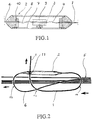
- the tap 2 contains one or more mechanical splices 3 which connect the optical fibers 4 and 8 to one another.
- the tap 2 consists of a pipe section 7, which was cut in half and is later assembled to the tap. In the middle of the tap there is a support 9 for receiving and holding the mechanical splices 3.
- the fibers 4 and 8 are located inside the tap in the form of a spiral, so that there is some excess length. This ensures that no tensile forces act on the fiber when forces occur in the longitudinal direction on the cables.
- FIG. 2 shows a branch from a stay cable.
- the FO cable branch consists of a cylindrical body (20 mm diameter), which is divided into two and at the tapered ends of which there are clamping devices for the cables.
- a cylindrical holder for mechanical splices 3 is fastened in the middle of the body.
- the house entry cable 1 (HEK) and the branch cable 6 are set down over a length of 30 cm, inserted into the cylinder and temporarily fixed with the help of the clamping devices.
- the fibers 4, 8 are connected to one another by the mechanical splice 3.
- the necessary fiber reserve is then set by loosening the clamping devices and pulling out the cables.
- the half-shell can be filled with gel, the body closed and the entire branch sealed with a shrink tube.
- the drop length of the branch cable is 1 m, from this a reserve length is obtained for a possible repeated repositioning of the fibers.
- the house entry cable 1 can be pre-assembled with a protection cylinder connected on one side and, due to the slim shape of the cylinder, can be routed from the house to the assembly through standard wall ducts and pipes.
- the second, free cable clamping device in the cylinder of the branch 2 can be used for a possible attachment of a towing eye.
- the cable piece to the subscriber (subscriber cable 1) is already connected to the tap 2 and delivered to the construction site in a pre-assembled manner.
- the optical fibers are already inserted into the mechanical splice 3 on one side.
- the cable only has to be stripped from the other side and the optical fibers inserted and inserted and locked in the mechanical splice.
- the upper half of the tap housing 7 must then be placed on and connected to the lower part in a watertight manner with a shrink tube.
- the pre-assembled end is inserted through the house entry into a prepared pipe until it is picked up at the dug-up point of the cable where the connection is to be made.
- the distance from the house entrance to the construction site is usually 3 to a maximum of 10 m.
- the advantage of the prefabricated branch is a reduction in costs due to the reduction in work on the construction site and the possibility of making work on site easier for the personnel.
- the advantage of the mechanical splice benefits the way of working in that the optical fibers can be inserted on one side in the factory and the splice can be fastened in the holder, so that only the other side has to be fitted. Another advantage is that with mechanical splices, the stripping lengths are only 20 - 30 mm.
- the branch cable 6 describes an arc 12 of 180 degrees before the introduction into the branch 2.
- the house entry cable 1 expediently describes arches 13 and 14 of a total of 270 Degree. The fact that it is attached to the tap 2 by a clamp 11, the house entry cable 1 is relieved of strain.
Landscapes
- Physics & Mathematics (AREA)
- General Physics & Mathematics (AREA)
- Optics & Photonics (AREA)
- Light Guides In General And Applications Therefor (AREA)
- Mechanical Coupling Of Light Guides (AREA)
Applications Claiming Priority (2)
| Application Number | Priority Date | Filing Date | Title |
|---|---|---|---|
| DE4141570A DE4141570A1 (de) | 1991-12-17 | 1991-12-17 | Lwl-verzweigungseinrichtung |
| DE4141570 | 1991-12-17 |
Publications (2)
| Publication Number | Publication Date |
|---|---|
| EP0547323A1 true EP0547323A1 (fr) | 1993-06-23 |
| EP0547323B1 EP0547323B1 (fr) | 1997-04-16 |
Family
ID=6447234
Family Applications (1)
| Application Number | Title | Priority Date | Filing Date |
|---|---|---|---|
| EP92117494A Expired - Lifetime EP0547323B1 (fr) | 1991-12-17 | 1992-10-14 | Dispositif de connexion des guides d'ondes optiques pour un branchement et méthode de connexion des guides d'ondes optiques à un branchement |
Country Status (2)
| Country | Link |
|---|---|
| EP (1) | EP0547323B1 (fr) |
| DE (2) | DE4141570A1 (fr) |
Cited By (2)
| Publication number | Priority date | Publication date | Assignee | Title |
|---|---|---|---|---|
| WO1994024597A1 (fr) * | 1993-04-16 | 1994-10-27 | Raychem Corporation | Systeme de cables a fibres optiques comportant un cable principal et des cables de derivation, et procede de fabrication associe |
| WO2002016978A3 (fr) * | 2000-08-24 | 2002-07-18 | Scc Special Comm Cables Gmbh | Multiplexeur/demultiplexeur dwdm a fibres optiques plan |
Families Citing this family (1)
| Publication number | Priority date | Publication date | Assignee | Title |
|---|---|---|---|---|
| DE19705649A1 (de) * | 1997-02-14 | 1998-08-20 | Alsthom Cge Alcatel | Anordnung zur Abzweigung an einem mehrere Verseilelemente mit optischen Fasern enthaltenden Fernmeldekabel |
Citations (5)
| Publication number | Priority date | Publication date | Assignee | Title |
|---|---|---|---|---|
| DE3301723A1 (de) * | 1983-01-20 | 1984-07-26 | ANT Nachrichtentechnik GmbH, 7150 Backnang | Muffe fuer lichtwellenleiterkabel |
| DE3537684A1 (de) * | 1985-10-23 | 1987-04-23 | Rheydt Kabelwerk Ag | Lichtwellenleiterkabel-abzweigung und verfahren zu deren herstellung |
| DE3605389A1 (de) * | 1986-02-20 | 1987-08-27 | Philips Patentverwaltung | Mit einer einziehverkappung versehenes ende eines insbesondere optischen kabels |
| EP0260741A2 (fr) * | 1986-09-09 | 1988-03-23 | Philips Patentverwaltung GmbH | Dérivation pour un câble optique avec plusieurs guides d'ondes lumineuses et procédé pour sa fabrication |
| DE8712964U1 (de) * | 1987-09-23 | 1989-01-19 | Siemens AG, 1000 Berlin und 8000 München | Rangierleitung |
Family Cites Families (4)
| Publication number | Priority date | Publication date | Assignee | Title |
|---|---|---|---|---|
| DE3273438D1 (en) * | 1981-10-08 | 1986-10-30 | British Telecomm | Improvements in the joining of optical fibre cables |
| US4799757A (en) * | 1987-04-21 | 1989-01-24 | Preformed Line Products Company | Encapsulated fiber optic closure |
| GB8815894D0 (en) * | 1988-07-04 | 1988-08-10 | Bicc Plc | Connecting device |
| SU1670657A1 (ru) * | 1989-04-05 | 1991-08-15 | Предприятие П/Я Г-4614 | Способ закреплени оптического волокна в трубчатом элементе |
-
1991
- 1991-12-17 DE DE4141570A patent/DE4141570A1/de not_active Withdrawn
-
1992
- 1992-10-14 EP EP92117494A patent/EP0547323B1/fr not_active Expired - Lifetime
- 1992-10-14 DE DE59208357T patent/DE59208357D1/de not_active Expired - Fee Related
Patent Citations (5)
| Publication number | Priority date | Publication date | Assignee | Title |
|---|---|---|---|---|
| DE3301723A1 (de) * | 1983-01-20 | 1984-07-26 | ANT Nachrichtentechnik GmbH, 7150 Backnang | Muffe fuer lichtwellenleiterkabel |
| DE3537684A1 (de) * | 1985-10-23 | 1987-04-23 | Rheydt Kabelwerk Ag | Lichtwellenleiterkabel-abzweigung und verfahren zu deren herstellung |
| DE3605389A1 (de) * | 1986-02-20 | 1987-08-27 | Philips Patentverwaltung | Mit einer einziehverkappung versehenes ende eines insbesondere optischen kabels |
| EP0260741A2 (fr) * | 1986-09-09 | 1988-03-23 | Philips Patentverwaltung GmbH | Dérivation pour un câble optique avec plusieurs guides d'ondes lumineuses et procédé pour sa fabrication |
| DE8712964U1 (de) * | 1987-09-23 | 1989-01-19 | Siemens AG, 1000 Berlin und 8000 München | Rangierleitung |
Non-Patent Citations (1)
| Title |
|---|
| PATENT ABSTRACTS OF JAPAN vol. 014, no. 389 (P-1095)(4332) 22. August 1990 & JP-A-02 146 003 ( NEC CORP ) * |
Cited By (2)
| Publication number | Priority date | Publication date | Assignee | Title |
|---|---|---|---|---|
| WO1994024597A1 (fr) * | 1993-04-16 | 1994-10-27 | Raychem Corporation | Systeme de cables a fibres optiques comportant un cable principal et des cables de derivation, et procede de fabrication associe |
| WO2002016978A3 (fr) * | 2000-08-24 | 2002-07-18 | Scc Special Comm Cables Gmbh | Multiplexeur/demultiplexeur dwdm a fibres optiques plan |
Also Published As
| Publication number | Publication date |
|---|---|
| DE59208357D1 (de) | 1997-05-22 |
| EP0547323B1 (fr) | 1997-04-16 |
| DE4141570A1 (de) | 1993-06-24 |
Similar Documents
| Publication | Publication Date | Title |
|---|---|---|
| DE69601616T2 (de) | Installationsverfahren für ein Abzweigröhrensystem bei Telekommunikationskabeln und Abzweigelement zum Gebrauch bei besagtem Verfahren | |
| EP0859257B1 (fr) | Dispositif pour le branchement d'un câble de télécommunications contenant plusieurs éléments de câblage comportant des fibres optiques | |
| DE60223167T2 (de) | Faseroptisches anschlusskabel | |
| DE19734274B4 (de) | Kommunikationsnetz mit Lichtwellenleitern zwischen Teilnehmern und Kommunikationzentralen in bestehenden Versorgungsleitungen | |
| EP0875777A2 (fr) | Manchon de câble pour câble à guide d'ondes optiques | |
| EP0547323A1 (fr) | Dispositif de branchement des guides d'ondes lumineuses | |
| DE69602790T2 (de) | Verfahren zum Feuchtigkeitsentzug eines hohlen Führungselementen wie beispielsweise Kabelschächte | |
| DE102019117612B4 (de) | Kabel-Rohrverband, Verfahren zur Herstellung und Verlegung | |
| DE19613733C1 (de) | Verzweigungsanordnung für ein vieladriges Lichtwellenleiterkabel | |
| EP0509299B1 (fr) | Câble optique | |
| DE19623482A1 (de) | Verfahren zum Anschluß eines Mikrokabels mit Lichtwellenleitern an ein bestehendes Lichtwellenleiter-Übertragungssystem | |
| DE4214039C2 (de) | Vorrichtung zum Aufteilen von Lichtwellenleitern eines optischen Kabels | |
| DE19601576A1 (de) | Kabelmuffe für Lichtwellenleiter mit Spleißkassetten und Überlängenablagen | |
| DE4314520C1 (de) | Bausatz für Kabelmuffen | |
| DE4309538A1 (de) | Verzweigungseinrichtung | |
| DE19750932C1 (de) | Glasfaser-Abschlußmodul und Einrichtung der Daten- und Telekommunikationstechnik | |
| DE19741433B4 (de) | Mikrokabel, bestehend aus einem Rohr und darin längsverlaufend eingebrachten Lichtwellenleitern | |
| EP4174547B1 (fr) | Faisceau de câbles | |
| DE102022117616B4 (de) | Proaktive Verlegung eines Kabel-Rohrverbandes für Glasfaserkabel | |
| DE19538376A1 (de) | Verfahren zum Einziehen mindestens eines langgestreckten, flexiblen Elementes, insbesondere eines Kabels oder Lichtwellenleiters in ein Kanalsystem großer Länge | |
| DE3428562A1 (de) | Spleisstraeger fuer lichtwellenleiterkabel | |
| WO2003060585A1 (fr) | Procede de pose d'un cable a fibres optiques dans une canalisation de gaz et dispositif de pose de cables correspondant | |
| DE3120058A1 (de) | Vorrichtung zum verlegen von elektrischen kabeln oder leitungen im erdboden | |
| DE9311129U1 (de) | Spleißkassette für eine Kabelgarnitur mit Lichtwellenleiterkabeln | |
| DE3120057A1 (de) | "vorrichtung zum verlegen von elektrischen kabeln oder leitungen im erdboden" |
Legal Events
| Date | Code | Title | Description |
|---|---|---|---|
| PUAI | Public reference made under article 153(3) epc to a published international application that has entered the european phase |
Free format text: ORIGINAL CODE: 0009012 |
|
| 17P | Request for examination filed |
Effective date: 19930429 |
|
| AK | Designated contracting states |
Kind code of ref document: A1 Designated state(s): DE FR GB IT NL |
|
| 17Q | First examination report despatched |
Effective date: 19950316 |
|
| GRAG | Despatch of communication of intention to grant |
Free format text: ORIGINAL CODE: EPIDOS AGRA |
|
| GRAH | Despatch of communication of intention to grant a patent |
Free format text: ORIGINAL CODE: EPIDOS IGRA |
|
| GRAH | Despatch of communication of intention to grant a patent |
Free format text: ORIGINAL CODE: EPIDOS IGRA |
|
| GRAH | Despatch of communication of intention to grant a patent |
Free format text: ORIGINAL CODE: EPIDOS IGRA |
|
| GRAA | (expected) grant |
Free format text: ORIGINAL CODE: 0009210 |
|
| ITF | It: translation for a ep patent filed | ||
| AK | Designated contracting states |
Kind code of ref document: B1 Designated state(s): DE FR GB IT NL |
|
| GBT | Gb: translation of ep patent filed (gb section 77(6)(a)/1977) |
Effective date: 19970428 |
|
| REF | Corresponds to: |
Ref document number: 59208357 Country of ref document: DE Date of ref document: 19970522 |
|
| ET | Fr: translation filed | ||
| PLBE | No opposition filed within time limit |
Free format text: ORIGINAL CODE: 0009261 |
|
| STAA | Information on the status of an ep patent application or granted ep patent |
Free format text: STATUS: NO OPPOSITION FILED WITHIN TIME LIMIT |
|
| 26N | No opposition filed | ||
| PGFP | Annual fee paid to national office [announced via postgrant information from national office to epo] |
Ref country code: GB Payment date: 20010914 Year of fee payment: 10 |
|
| PGFP | Annual fee paid to national office [announced via postgrant information from national office to epo] |
Ref country code: NL Payment date: 20010925 Year of fee payment: 10 |
|
| PGFP | Annual fee paid to national office [announced via postgrant information from national office to epo] |
Ref country code: DE Payment date: 20011005 Year of fee payment: 10 |
|
| PGFP | Annual fee paid to national office [announced via postgrant information from national office to epo] |
Ref country code: FR Payment date: 20011011 Year of fee payment: 10 |
|
| REG | Reference to a national code |
Ref country code: GB Ref legal event code: IF02 |
|
| PG25 | Lapsed in a contracting state [announced via postgrant information from national office to epo] |
Ref country code: GB Free format text: LAPSE BECAUSE OF NON-PAYMENT OF DUE FEES Effective date: 20021014 |
|
| PG25 | Lapsed in a contracting state [announced via postgrant information from national office to epo] |
Ref country code: NL Free format text: LAPSE BECAUSE OF NON-PAYMENT OF DUE FEES Effective date: 20030501 Ref country code: DE Free format text: LAPSE BECAUSE OF NON-PAYMENT OF DUE FEES Effective date: 20030501 |
|
| GBPC | Gb: european patent ceased through non-payment of renewal fee |
Effective date: 20021014 |
|
| PG25 | Lapsed in a contracting state [announced via postgrant information from national office to epo] |
Ref country code: FR Free format text: LAPSE BECAUSE OF NON-PAYMENT OF DUE FEES Effective date: 20030630 |
|
| NLV4 | Nl: lapsed or anulled due to non-payment of the annual fee |
Effective date: 20030501 |
|
| REG | Reference to a national code |
Ref country code: FR Ref legal event code: ST |
|
| PG25 | Lapsed in a contracting state [announced via postgrant information from national office to epo] |
Ref country code: IT Free format text: LAPSE BECAUSE OF NON-PAYMENT OF DUE FEES;WARNING: LAPSES OF ITALIAN PATENTS WITH EFFECTIVE DATE BEFORE 2007 MAY HAVE OCCURRED AT ANY TIME BEFORE 2007. THE CORRECT EFFECTIVE DATE MAY BE DIFFERENT FROM THE ONE RECORDED. Effective date: 20051014 |