EP0547367A1 - Soupape de commutation pour fluide hydraulique ou pneumatique - Google Patents
Soupape de commutation pour fluide hydraulique ou pneumatique Download PDFInfo
- Publication number
- EP0547367A1 EP0547367A1 EP92119172A EP92119172A EP0547367A1 EP 0547367 A1 EP0547367 A1 EP 0547367A1 EP 92119172 A EP92119172 A EP 92119172A EP 92119172 A EP92119172 A EP 92119172A EP 0547367 A1 EP0547367 A1 EP 0547367A1
- Authority
- EP
- European Patent Office
- Prior art keywords
- valve
- housing
- pressure medium
- throttle
- medium connection
- Prior art date
- Legal status (The legal status is an assumption and is not a legal conclusion. Google has not performed a legal analysis and makes no representation as to the accuracy of the status listed.)
- Granted
Links
Images




Classifications
-
- F—MECHANICAL ENGINEERING; LIGHTING; HEATING; WEAPONS; BLASTING
- F15—FLUID-PRESSURE ACTUATORS; HYDRAULICS OR PNEUMATICS IN GENERAL
- F15B—SYSTEMS ACTING BY MEANS OF FLUIDS IN GENERAL; FLUID-PRESSURE ACTUATORS, e.g. SERVOMOTORS; DETAILS OF FLUID-PRESSURE SYSTEMS, NOT OTHERWISE PROVIDED FOR
- F15B11/00—Servomotor systems without provision for follow-up action; Circuits therefor
- F15B11/02—Systems essentially incorporating special features for controlling the speed or actuating force of an output member
- F15B11/04—Systems essentially incorporating special features for controlling the speed or actuating force of an output member for controlling the speed
- F15B11/044—Systems essentially incorporating special features for controlling the speed or actuating force of an output member for controlling the speed by means in the return line, i.e. "meter out"
-
- F—MECHANICAL ENGINEERING; LIGHTING; HEATING; WEAPONS; BLASTING
- F15—FLUID-PRESSURE ACTUATORS; HYDRAULICS OR PNEUMATICS IN GENERAL
- F15B—SYSTEMS ACTING BY MEANS OF FLUIDS IN GENERAL; FLUID-PRESSURE ACTUATORS, e.g. SERVOMOTORS; DETAILS OF FLUID-PRESSURE SYSTEMS, NOT OTHERWISE PROVIDED FOR
- F15B11/00—Servomotor systems without provision for follow-up action; Circuits therefor
- F15B11/02—Systems essentially incorporating special features for controlling the speed or actuating force of an output member
- F15B11/04—Systems essentially incorporating special features for controlling the speed or actuating force of an output member for controlling the speed
- F15B11/042—Systems essentially incorporating special features for controlling the speed or actuating force of an output member for controlling the speed by means in the feed line, i.e. "meter in"
-
- F—MECHANICAL ENGINEERING; LIGHTING; HEATING; WEAPONS; BLASTING
- F15—FLUID-PRESSURE ACTUATORS; HYDRAULICS OR PNEUMATICS IN GENERAL
- F15B—SYSTEMS ACTING BY MEANS OF FLUIDS IN GENERAL; FLUID-PRESSURE ACTUATORS, e.g. SERVOMOTORS; DETAILS OF FLUID-PRESSURE SYSTEMS, NOT OTHERWISE PROVIDED FOR
- F15B13/00—Details of servomotor systems ; Valves for servomotor systems
- F15B13/02—Fluid distribution or supply devices characterised by their adaptation to the control of servomotors
- F15B13/04—Fluid distribution or supply devices characterised by their adaptation to the control of servomotors for use with a single servomotor
- F15B13/0401—Valve members; Fluid interconnections therefor
- F15B13/0405—Valve members; Fluid interconnections therefor for seat valves, i.e. poppet valves
-
- F—MECHANICAL ENGINEERING; LIGHTING; HEATING; WEAPONS; BLASTING
- F16—ENGINEERING ELEMENTS AND UNITS; GENERAL MEASURES FOR PRODUCING AND MAINTAINING EFFECTIVE FUNCTIONING OF MACHINES OR INSTALLATIONS; THERMAL INSULATION IN GENERAL
- F16K—VALVES; TAPS; COCKS; ACTUATING-FLOATS; DEVICES FOR VENTING OR AERATING
- F16K1/00—Lift valves or globe valves, i.e. cut-off apparatus with closure members having at least a component of their opening and closing motion perpendicular to the closing faces
- F16K1/32—Details
- F16K1/52—Means for additional adjustment of the rate of flow
-
- F—MECHANICAL ENGINEERING; LIGHTING; HEATING; WEAPONS; BLASTING
- F15—FLUID-PRESSURE ACTUATORS; HYDRAULICS OR PNEUMATICS IN GENERAL
- F15B—SYSTEMS ACTING BY MEANS OF FLUIDS IN GENERAL; FLUID-PRESSURE ACTUATORS, e.g. SERVOMOTORS; DETAILS OF FLUID-PRESSURE SYSTEMS, NOT OTHERWISE PROVIDED FOR
- F15B2211/00—Circuits for servomotor systems
- F15B2211/30—Directional control
- F15B2211/305—Directional control characterised by the type of valves
- F15B2211/30525—Directional control valves, e.g. 4/3-directional control valve
-
- F—MECHANICAL ENGINEERING; LIGHTING; HEATING; WEAPONS; BLASTING
- F15—FLUID-PRESSURE ACTUATORS; HYDRAULICS OR PNEUMATICS IN GENERAL
- F15B—SYSTEMS ACTING BY MEANS OF FLUIDS IN GENERAL; FLUID-PRESSURE ACTUATORS, e.g. SERVOMOTORS; DETAILS OF FLUID-PRESSURE SYSTEMS, NOT OTHERWISE PROVIDED FOR
- F15B2211/00—Circuits for servomotor systems
- F15B2211/30—Directional control
- F15B2211/31—Directional control characterised by the positions of the valve element
- F15B2211/3105—Neutral or centre positions
- F15B2211/3111—Neutral or centre positions the pump port being closed in the centre position, e.g. so-called closed centre
-
- F—MECHANICAL ENGINEERING; LIGHTING; HEATING; WEAPONS; BLASTING
- F15—FLUID-PRESSURE ACTUATORS; HYDRAULICS OR PNEUMATICS IN GENERAL
- F15B—SYSTEMS ACTING BY MEANS OF FLUIDS IN GENERAL; FLUID-PRESSURE ACTUATORS, e.g. SERVOMOTORS; DETAILS OF FLUID-PRESSURE SYSTEMS, NOT OTHERWISE PROVIDED FOR
- F15B2211/00—Circuits for servomotor systems
- F15B2211/30—Directional control
- F15B2211/31—Directional control characterised by the positions of the valve element
- F15B2211/3122—Special positions other than the pump port being connected to working ports or the working ports being connected to the return line
- F15B2211/3127—Floating position connecting the working ports and the return line
-
- F—MECHANICAL ENGINEERING; LIGHTING; HEATING; WEAPONS; BLASTING
- F15—FLUID-PRESSURE ACTUATORS; HYDRAULICS OR PNEUMATICS IN GENERAL
- F15B—SYSTEMS ACTING BY MEANS OF FLUIDS IN GENERAL; FLUID-PRESSURE ACTUATORS, e.g. SERVOMOTORS; DETAILS OF FLUID-PRESSURE SYSTEMS, NOT OTHERWISE PROVIDED FOR
- F15B2211/00—Circuits for servomotor systems
- F15B2211/30—Directional control
- F15B2211/32—Directional control characterised by the type of actuation
- F15B2211/327—Directional control characterised by the type of actuation electrically or electronically
-
- F—MECHANICAL ENGINEERING; LIGHTING; HEATING; WEAPONS; BLASTING
- F15—FLUID-PRESSURE ACTUATORS; HYDRAULICS OR PNEUMATICS IN GENERAL
- F15B—SYSTEMS ACTING BY MEANS OF FLUIDS IN GENERAL; FLUID-PRESSURE ACTUATORS, e.g. SERVOMOTORS; DETAILS OF FLUID-PRESSURE SYSTEMS, NOT OTHERWISE PROVIDED FOR
- F15B2211/00—Circuits for servomotor systems
- F15B2211/40—Flow control
- F15B2211/405—Flow control characterised by the type of flow control means or valve
- F15B2211/40515—Flow control characterised by the type of flow control means or valve with variable throttles or orifices
-
- F—MECHANICAL ENGINEERING; LIGHTING; HEATING; WEAPONS; BLASTING
- F15—FLUID-PRESSURE ACTUATORS; HYDRAULICS OR PNEUMATICS IN GENERAL
- F15B—SYSTEMS ACTING BY MEANS OF FLUIDS IN GENERAL; FLUID-PRESSURE ACTUATORS, e.g. SERVOMOTORS; DETAILS OF FLUID-PRESSURE SYSTEMS, NOT OTHERWISE PROVIDED FOR
- F15B2211/00—Circuits for servomotor systems
- F15B2211/40—Flow control
- F15B2211/42—Flow control characterised by the type of actuation
- F15B2211/428—Flow control characterised by the type of actuation actuated by fluid pressure
-
- F—MECHANICAL ENGINEERING; LIGHTING; HEATING; WEAPONS; BLASTING
- F15—FLUID-PRESSURE ACTUATORS; HYDRAULICS OR PNEUMATICS IN GENERAL
- F15B—SYSTEMS ACTING BY MEANS OF FLUIDS IN GENERAL; FLUID-PRESSURE ACTUATORS, e.g. SERVOMOTORS; DETAILS OF FLUID-PRESSURE SYSTEMS, NOT OTHERWISE PROVIDED FOR
- F15B2211/00—Circuits for servomotor systems
- F15B2211/40—Flow control
- F15B2211/45—Control of bleed-off flow, e.g. control of bypass flow to the return line
-
- F—MECHANICAL ENGINEERING; LIGHTING; HEATING; WEAPONS; BLASTING
- F15—FLUID-PRESSURE ACTUATORS; HYDRAULICS OR PNEUMATICS IN GENERAL
- F15B—SYSTEMS ACTING BY MEANS OF FLUIDS IN GENERAL; FLUID-PRESSURE ACTUATORS, e.g. SERVOMOTORS; DETAILS OF FLUID-PRESSURE SYSTEMS, NOT OTHERWISE PROVIDED FOR
- F15B2211/00—Circuits for servomotor systems
- F15B2211/40—Flow control
- F15B2211/455—Control of flow in the feed line, i.e. meter-in control
-
- F—MECHANICAL ENGINEERING; LIGHTING; HEATING; WEAPONS; BLASTING
- F15—FLUID-PRESSURE ACTUATORS; HYDRAULICS OR PNEUMATICS IN GENERAL
- F15B—SYSTEMS ACTING BY MEANS OF FLUIDS IN GENERAL; FLUID-PRESSURE ACTUATORS, e.g. SERVOMOTORS; DETAILS OF FLUID-PRESSURE SYSTEMS, NOT OTHERWISE PROVIDED FOR
- F15B2211/00—Circuits for servomotor systems
- F15B2211/40—Flow control
- F15B2211/46—Control of flow in the return line, i.e. meter-out control
-
- F—MECHANICAL ENGINEERING; LIGHTING; HEATING; WEAPONS; BLASTING
- F15—FLUID-PRESSURE ACTUATORS; HYDRAULICS OR PNEUMATICS IN GENERAL
- F15B—SYSTEMS ACTING BY MEANS OF FLUIDS IN GENERAL; FLUID-PRESSURE ACTUATORS, e.g. SERVOMOTORS; DETAILS OF FLUID-PRESSURE SYSTEMS, NOT OTHERWISE PROVIDED FOR
- F15B2211/00—Circuits for servomotor systems
- F15B2211/70—Output members, e.g. hydraulic motors or cylinders or control therefor
- F15B2211/705—Output members, e.g. hydraulic motors or cylinders or control therefor characterised by the type of output members or actuators
- F15B2211/7051—Linear output members
- F15B2211/7053—Double-acting output members
-
- F—MECHANICAL ENGINEERING; LIGHTING; HEATING; WEAPONS; BLASTING
- F15—FLUID-PRESSURE ACTUATORS; HYDRAULICS OR PNEUMATICS IN GENERAL
- F15B—SYSTEMS ACTING BY MEANS OF FLUIDS IN GENERAL; FLUID-PRESSURE ACTUATORS, e.g. SERVOMOTORS; DETAILS OF FLUID-PRESSURE SYSTEMS, NOT OTHERWISE PROVIDED FOR
- F15B2211/00—Circuits for servomotor systems
- F15B2211/70—Output members, e.g. hydraulic motors or cylinders or control therefor
- F15B2211/75—Control of speed of the output member
-
- F—MECHANICAL ENGINEERING; LIGHTING; HEATING; WEAPONS; BLASTING
- F15—FLUID-PRESSURE ACTUATORS; HYDRAULICS OR PNEUMATICS IN GENERAL
- F15B—SYSTEMS ACTING BY MEANS OF FLUIDS IN GENERAL; FLUID-PRESSURE ACTUATORS, e.g. SERVOMOTORS; DETAILS OF FLUID-PRESSURE SYSTEMS, NOT OTHERWISE PROVIDED FOR
- F15B2211/00—Circuits for servomotor systems
- F15B2211/70—Output members, e.g. hydraulic motors or cylinders or control therefor
- F15B2211/77—Control of direction of movement of the output member
- F15B2211/7741—Control of direction of movement of the output member with floating mode, e.g. using a direct connection between both lines of a double-acting cylinder
Definitions
- the invention relates to a switching valve for pneumatic or hydraulic pressure medium with a housing which has a first and a second pressure medium connection, which are each connected to a flow space for the pressure medium, and a valve member arranged in the housing, which cooperates with a valve seat as a valve arrangement.
- Known switching valves are also used, for example, to control handling machines or other hydraulic or pneumatic drives.
- All of these valves usually have a flow gap and no flow space, with the result that the medium flowing through experiences a non-negligible pressure drop when flowing through these valves, which leads to a reduction in the rapid traverse speed.
- valve member can be moved in a controlled manner while simultaneously changing the volume of the flow space, in order to change the free flow cross section of the valve in such a way that when the valve is opened a volume increase and when the valve closes, the volume of the flow space is reduced.
- the flow rate of the pressure medium is changed in a simple manner, which at the same time causes a change in the speed of movement of the drive element acted upon by the pressure medium.
- the drive member can be accelerated or decelerated in a controlled manner, so that a smooth, continuous change in speed of the drive member is made possible.
- valve is designed as a piston and the housing has a cylinder section in which the piston is accommodated in an axially displaceable manner.
- valve member can also be designed as a membrane which is received in the housing cavity.
- the switching valve can in turn be controlled hydraulically or pneumatically.
- a throttle opening between the first and second pressure medium connection according to claim 5 allows the setting of a flow cross-section for the pressure medium which is open regardless of the position of the switching valve, as a result of which a minimum drive speed of the drive element can be predetermined.
- the throttle opening can be changeable according to claim 6 with a throttle valve, so that the minimum speed of the drive member can be changed or fixedly adjusted by setting the effective cross section of the throttle opening.
- the drive element can be brought to a complete standstill when the switching valve and the throttle valve are closed.
- the switching valve can initially continuously with the throttle valve open are closed, whereby the speed of the drive element is continuously reduced to the minimum speed predetermined by the throttle valve, and from this minimum speed the drive element can then be braked to a standstill by closing the throttle valve.
- a particularly advantageous construction of the switching valve is specified in claim 8, wherein the tubular extension is preferably arranged axially, so that the piston with its end face acting as a sealing surface can come into sealing contact with the valve seat formed at the free end of the extension.
- a particularly effective arrangement of the throttle valve is specified in claim 9.
- the structure of the housing according to claim 10 allows economical manufacture of the housing and an operationally reliable function of the switching valve.
- the switching valve according to claim 11 combines in a particularly compact design in one housing two independently working and individually controllable valve arrangements.
- FIG. 1 shows a switching valve with a housing 1, which is provided from a housing base body 7 with a housing cavity 71, which is open on one side and is closed by a connecting flange 2.
- the connecting flange 2 has a projecting section 21 which engages by means of a seal 23 sealingly in the opening of the housing cavity 71 and closes the housing cavity 71.
- the housing cavity 71 is designed as a cylinder section 70.
- a piston 3 is arranged axially displaceably in the cylinder section 70.
- the piston 3 has a piston rod 30, which is sealingly led out of the housing 1 through an axial bore 73 of the basic housing body 7.
- the piston 3 divides the housing cavity 71 into a flow space 72 formed between the piston 3 and the connecting flange 2 and a control pressure space 74 formed on the side of the piston facing away from the connecting flange 2.
- the control pressure chamber 74 is connected via a channel 75 to the control pressure connection 12 in the wall of the basic housing body 7.
- a line 50 connects the control pressure connection 12 to a pilot valve 5.
- the pilot valve 5 is pressurized by a pressure source 51.
- the pilot valve 5 can be triggered either by a control signal S acting on an electromagnetic actuating element 52 or, alternatively, by a mechanical actuating element 53 which, for example, from the setting 54 of an actuating device can be acted upon.
- the projecting section 21 of the connecting flange 2 engaging in the housing cavity 71 is provided with an essentially tubular extension 28, the free end of which extends essentially coaxially with the axis 76 of the cylinder section 70.
- the tubular extension 28 has a preferably coaxial channel 27 which is connected to the second pressure medium connection 20 formed in the connecting flange.
- the channel 27 opens into the flow space 72, a valve seat 22 being formed at the mouth 26, against which the end face 31 of the piston 3 can be moved to seal the channel 27 with respect to the flow space 72.
- the flow space 72 forms an annular space 72 '.
- the essentially radially extending first pressure medium connection 10 is provided in the side wall of the housing base body 7 at the level of the annular space 72 '.
- a radially extending throttle opening 24 is provided in the wall of the tubular extension 28 on the side diagonally opposite the first pressure medium connection 10.
- a throttle pin 40 engages with its conical sealing surface 42 in the throttle opening 24.
- the throttle pin 40 is provided on its shaft section with an external thread 41, which is guided in an internal thread 77 in the wall of the basic housing body 7.
- the throttle pin 40 is provided at its free end 43 protruding from the housing 1 with an attachment surface for a tool, for example a screwdriver or a polygonal key.
- a nut 44 screwed onto the section of the throttle pin 40 protruding from the housing 1 serves to lock the throttle pin 40 against the wall of the housing base body 7.
- the pilot valve 5 is activated via the control signal S acting on the electromagnetic actuating element 52 or the switching link 54 acting on the mechanical actuating element 53 actuated, thereby creating a passage for the pressure medium supplied by the pressure source 51 into the line 50 and thus through the control pressure connection 12 into the control pressure chamber 74.
- the medium flowing out of the pressure source 51 penetrates into the control pressure chamber 74 and in doing so moves the piston 3 continuously against the free end of the tubular extension 28 (upwards in FIG. 1) until the piston with its end face 31 comes into contact with the valve seat 22 and seals the mouth 26 of the channel 27 into the flow space 72.
- the volume of the flow space 72 is continuously reduced, so that the usable free flow cross section in the valve for the medium flowing through the flow space 72 continuously decreases, thereby increasing the flow resistance of the volume flow of the pressure medium is reduced by the valve.
- the speed of the drive actuated by the pressure fluid is also continuously reduced.
- the throttle opening 24 which is adjustable by the throttle valve 4.
- the volume flow of the pressure medium flowing through this throttle opening determines the minimum speed achievable in the drive acted upon by the pressure medium.
- FIG 2 shows a switching valve corresponding to the switching valve of Figure 1 with a housing base body 7, a connecting flange 2 and a piston 3, in which instead of the threaded and screwed into the wall of the housing base body 7 throttle pin 40 in a radial bore 41 'of the wall of the housing base body 7, a displaceable throttle pin 40 'is provided, which likewise has a conical sealing surface 42' which engages in the throttle opening 24 '.
- the throttle pin 40 ' is acted upon by a switching magnet 45 which permits movement of the throttle pin between a closed position in which the conical sealing surface 42' of the throttle pin 40 'closes the throttle opening 24' and a position which can be predetermined.
- the throttle opening 24 can be closed by actuating the switching magnet 45, for example after the minimum speed has been reached, so that the flow through the flow space 72 is completely interrupted.
- the drive element acted upon by the pressure medium therefore comes to a standstill.
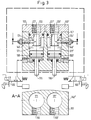
- FIG. 3 shows an arrangement of two switching valves of the type shown in FIG. 1 in a common housing block 107.
- Two housing cavities 171, 171 ' are formed in the housing block 107, in each of which a piston 103, 103' axially, as in the embodiment in FIG is slidably received.
- Each of the cavities 171, 171 ' is closed by a connecting flange 102, 102'.
- Each connecting flange 102, 102 ' is provided with a second pressure medium connection 120, 120' running coaxially to the piston axis 176, 176 ', each of which has a coaxial channel 127, 127' with the associated one Housing cavity 171, 171 'communicates.
- Throttle pins 140, 140 'for setting the respective throttle opening 124, 124' are formed on two sides of the housing base body 107 facing away from one another and each correspond to the construction in FIG. 1.
- the first pressure medium connections 110, 110 'provided in the housing wall of the housing base body 107 are at right angles to the common axial direction 140' 'of the throttle pins 140, 140' and are both arranged in the same outer wall of the housing base body 107 as that in the lower half of FIG. 3 shown section AA shows. (To simplify matters, the throttle pins 140, 140 'are not shown in section AA, but only their common axis 140' '.)
- the pistons 103, 103 ' are controlled as in the example described with reference to FIG. 1 via the pilot valves 105, 105'.
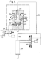
- FIG. 4 shows an application example of the switching valve according to FIG. 1, in which the switching valve is used to control the exhaust air of a pneumatic motor 208.
- the pneumatic motor 208 is acted upon by a pressure medium source 281, a preferably magnetically actuated control valve 280 arranged between the pressure medium source 281 and the pneumatic motor 208 specifying the direction of rotation of the pneumatic motor 208.
- the exhaust air line 282, 283 directs the exhaust air flowing out of the pneumatic motor 208 to the second pressure medium connection 220 of the control valve.
- a muffler 284 is arranged, which emits the exhaust air flowing out of the switching valve in a silenced manner into the open.
- the piston 203 If the pressure in the control pressure chamber 274 is reduced by renewed actuation of the pilot valve 205, the piston 203 returns to its open position due to the exhaust air pressure of the pneumatic motor 208 acting on it. The piston 203 is moved back while continuously displacing the control pressure medium from the control pressure space 274, so that the flow space 272 increases continuously and thus the free flow cross section in the switching valve increases continuously, which in turn leads to a continuous speed increase in the pneumatic motor 208.
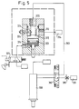
- FIG. 5 shows a structure similar to that in FIG. 4, the switching valve of FIG. 1 also being used, but relating to operation with a hydraulic motor 308.
- the hydraulic motor 308 is driven by a pressure source 381, which is connected to the pneumatic motor 308 via an inlet throttle 385 and a valve 380 for controlling the direction of rotation.
- the return line 383 for the hydraulic fluid flowing out of the pneumatic motor 308 is led to the second pressure medium connection 320 of the switching valve.
- a drain line leads from the first pressure medium connection 310 of the switching valve to a hydraulic return tank 384.
- the rotational speed of the hydraulic motor 308 is braked down to a slower speed while forming an adjustable dynamic pressure in the return line 383 in accordance with the throttle cross section of the throttle opening 324 set by the throttle valve 304.
- FIG 6 the double valve of Figure 3 is shown in an example application.
- two separate media spaces 486, 487 of a pneumatic cylinder 408 can be individually controlled.
- the direction of movement of the pneumatic cylinder 408 can be determined via the control valve 480 connected to a compressed air source 481.
- the supply air flows via the connecting line 482 'according to the arrow V through the first pressure medium connection 410' into the flow space 472 '. From there, the compressed air flows through the second pressure medium connection 420 'into the first media space 486 of the pneumatic cylinder 408, as a result of which the piston 408' of the pneumatic cylinder is moved to the left in FIG. 6 (arrow W).
- the air emerging from the second media space 487 of the pneumatic cylinder 408 flows through the second pressure medium connection 420 of the second switching valve of this valve block into the flow space 472 and out of this through the first pressure medium connection 410 according to the arrow U via the connecting line 482 and the muffler 484 of the quick exhaust valve 485 .
- the pilot valve 405 is actuated when the control signal S' and the switching signal T 'are simultaneously applied, as a result of which pressure medium flows from the pressure medium source 451 into the control pressure chamber 474 and the piston 403 is reduced of the flow space 472 until it contacts the valve seat 422.
- the counterpressure thus created in the second switching valve of the valve block hinders the outflow of the exhaust air from the second media space 487 of the pneumatic cylinder 408 and thus brakes the movement of the piston 408 'down to the creep speed set by means of the throttle valve 404, so that the piston 408 'of the pneumatic cylinder with the set creep speed approaches the cylinder bottom of the second media room 487 and comes to rest there.
- FIG. 7 shows an arrangement analogous to FIG. 6, but with a hydraulic cylinder 508 being driven.
- the arrangement shown in FIG. 7 functions analogously to the arrangement shown in FIG. 6, the pressure fluid flowing from a pressure source 581 through a valve 580 directly to the first pressure medium connection 510, 510 'of the piston 508' of the hydraulic cylinder 508 assigned to the desired direction of movement Switch valve block is supplied.
- the returning pressure fluid then flows from the respective other first pressure medium connection 510 ', 510 into the return tank 584.
- the switching valve of the invention which is designed as a positioning switching block, in particular for pneumatic or hydraulic high-speed axis drives, can be used for reversing from rapid traverse to creep speed in hydraulic or pneumatic motors, in hydraulic or pneumatic piston-cylinder drives or also in hydraulic or pneumatic rotary piston drives. Adaptation to existing piping can take place outside the switching valve by measures known to the person skilled in the art.
Landscapes
- Engineering & Computer Science (AREA)
- General Engineering & Computer Science (AREA)
- Mechanical Engineering (AREA)
- Physics & Mathematics (AREA)
- Fluid Mechanics (AREA)
- Fluid-Driven Valves (AREA)
- Multiple-Way Valves (AREA)
- Fluid-Pressure Circuits (AREA)
Applications Claiming Priority (2)
| Application Number | Priority Date | Filing Date | Title |
|---|---|---|---|
| DE4141205 | 1991-12-13 | ||
| DE4141205A DE4141205A1 (de) | 1991-12-13 | 1991-12-13 | Schaltventil fuer pneumatische oder hydraulische druckmittel |
Publications (2)
| Publication Number | Publication Date |
|---|---|
| EP0547367A1 true EP0547367A1 (fr) | 1993-06-23 |
| EP0547367B1 EP0547367B1 (fr) | 1996-09-18 |
Family
ID=6447010
Family Applications (1)
| Application Number | Title | Priority Date | Filing Date |
|---|---|---|---|
| EP92119172A Expired - Lifetime EP0547367B1 (fr) | 1991-12-13 | 1992-11-09 | Soupape de commutation pour fluide hydraulique ou pneumatique |
Country Status (4)
| Country | Link |
|---|---|
| EP (1) | EP0547367B1 (fr) |
| AT (1) | ATE143112T1 (fr) |
| DE (2) | DE4141205A1 (fr) |
| ES (1) | ES2091994T3 (fr) |
Cited By (1)
| Publication number | Priority date | Publication date | Assignee | Title |
|---|---|---|---|---|
| EP0844401A1 (fr) * | 1996-11-22 | 1998-05-27 | SMC Kabushiki Kaisha | Commande de vitesse avec clapet anti-retour piloté |
Families Citing this family (4)
| Publication number | Priority date | Publication date | Assignee | Title |
|---|---|---|---|---|
| DE20011585U1 (de) | 2000-07-03 | 2000-11-23 | bgu-Umweltschutzanlagen GmbH, 74626 Bretzfeld | Pneumatische Schaltung zur Betätigung eines Pneumatikzylinders und pneumatische Spüleinrichtung für Abwasserdrosselorgane |
| CN110158697B (zh) * | 2019-06-14 | 2024-04-30 | 江苏徐工工程机械研究院有限公司 | 信号切断阀以及液压控制系统 |
| US11598172B2 (en) * | 2021-01-25 | 2023-03-07 | The Sydco System, Inc. | Rotating head with bypass circuit |
| CN115574106B (zh) * | 2022-09-15 | 2025-09-23 | 河北华北石油荣盛机械制造有限公司 | 一种具有星形阀芯的耐冲蚀节流阀 |
Citations (6)
| Publication number | Priority date | Publication date | Assignee | Title |
|---|---|---|---|---|
| US2966170A (en) * | 1957-07-02 | 1960-12-27 | Otis Eng Co | Temperature compensated metering valve |
| CH351147A (de) * | 1957-07-12 | 1960-12-31 | Gebert & Cie | Eck-Drosselventil |
| US3107079A (en) * | 1961-07-03 | 1963-10-15 | Bendix Corp | Fluid metering shut-off valve |
| DE2215857A1 (de) * | 1971-03-30 | 1972-10-12 | Knapp, Alfons, Dr., 7950 Biberach | Fluid-Dosierventil mit einstellbarem Strömungswiderstand |
| US3752188A (en) * | 1971-03-30 | 1973-08-14 | A Sage | Valve with controlled flow characteristics |
| FR2214075A1 (fr) * | 1973-01-17 | 1974-08-09 | Festo Maschf Stoll G |
Family Cites Families (1)
| Publication number | Priority date | Publication date | Assignee | Title |
|---|---|---|---|---|
| SE461169B (sv) * | 1988-05-20 | 1990-01-15 | Inreco Ab | Reglerventil med instaellbart kapacitetsvaerde |
-
1991
- 1991-12-13 DE DE4141205A patent/DE4141205A1/de not_active Withdrawn
-
1992
- 1992-11-09 DE DE59207181T patent/DE59207181D1/de not_active Expired - Fee Related
- 1992-11-09 EP EP92119172A patent/EP0547367B1/fr not_active Expired - Lifetime
- 1992-11-09 AT AT92119172T patent/ATE143112T1/de not_active IP Right Cessation
- 1992-11-09 ES ES92119172T patent/ES2091994T3/es not_active Expired - Lifetime
Patent Citations (6)
| Publication number | Priority date | Publication date | Assignee | Title |
|---|---|---|---|---|
| US2966170A (en) * | 1957-07-02 | 1960-12-27 | Otis Eng Co | Temperature compensated metering valve |
| CH351147A (de) * | 1957-07-12 | 1960-12-31 | Gebert & Cie | Eck-Drosselventil |
| US3107079A (en) * | 1961-07-03 | 1963-10-15 | Bendix Corp | Fluid metering shut-off valve |
| DE2215857A1 (de) * | 1971-03-30 | 1972-10-12 | Knapp, Alfons, Dr., 7950 Biberach | Fluid-Dosierventil mit einstellbarem Strömungswiderstand |
| US3752188A (en) * | 1971-03-30 | 1973-08-14 | A Sage | Valve with controlled flow characteristics |
| FR2214075A1 (fr) * | 1973-01-17 | 1974-08-09 | Festo Maschf Stoll G |
Cited By (4)
| Publication number | Priority date | Publication date | Assignee | Title |
|---|---|---|---|---|
| EP0844401A1 (fr) * | 1996-11-22 | 1998-05-27 | SMC Kabushiki Kaisha | Commande de vitesse avec clapet anti-retour piloté |
| US6131610A (en) * | 1996-11-22 | 2000-10-17 | Smc Kabushiki Kaisha | Speed controller with pilot check valve |
| US6293180B1 (en) | 1996-11-22 | 2001-09-25 | Smc Kabushiki Kaisha | Speed controller with pilot check valve |
| US6296015B1 (en) | 1996-11-22 | 2001-10-02 | Smc Kabushiki Kaisha | Speed controller with pilot check valve |
Also Published As
| Publication number | Publication date |
|---|---|
| ATE143112T1 (de) | 1996-10-15 |
| DE59207181D1 (de) | 1996-10-24 |
| ES2091994T3 (es) | 1996-11-16 |
| DE4141205A1 (de) | 1993-06-17 |
| EP0547367B1 (fr) | 1996-09-18 |
Similar Documents
| Publication | Publication Date | Title |
|---|---|---|
| DE2635472C2 (de) | Servoeinrichtung zum Betätigen eines Steuerventils | |
| DE3011791C2 (de) | 5/2-Wegeventil in Schieberbauart für die Druckmittelversorgung eines Servomotors | |
| DE69426952T2 (de) | Pneumatischer Zylinder und Steuerventil dafür | |
| DE3347000A1 (de) | Elektrohydraulische einrichtung zur steuerung eines doppeltwirkenden hydromotors | |
| DE19843154A1 (de) | Zylinder mit Geschwindikeitssteuermechanismus | |
| EP1350960B1 (fr) | Dispositif d'entraínement actionné par fluide | |
| EP0547367B1 (fr) | Soupape de commutation pour fluide hydraulique ou pneumatique | |
| DE2625063A1 (de) | Steuervorrichtung zur geschwindigkeitsregelung von pneumatischen und/oder hydraulischen arbeitskolben | |
| EP1042615B1 (fr) | Dispositif de travail actionne par un fluide | |
| DE1925166B2 (de) | Hydraulische betaetigungsvorrichtung fuer elektrische hochspannungsschalter | |
| EP0220248B1 (fr) | Systeme pour le reglage de l'amplification de circuit d'un circuit de servo-regulation | |
| DE19950910A1 (de) | Hydraulisches Antriebssystem und darin verwendbares hydraulisches 4/3-Wegeventil | |
| DE4422528A1 (de) | Fluidbetätigte Antriebseinheit | |
| DD233402A5 (de) | Keilschieber | |
| DE20101049U1 (de) | Antriebsvorrichtung | |
| DE2161459B2 (de) | Hydrostatisch angetriebene Doppelpumpe | |
| EP0074496B1 (fr) | Dispositif de vanne, en particulier pour machine à moulage sous pression | |
| DE102023135718A1 (de) | Ventilanordnung und damit ausgestattetes Antriebssystem | |
| DE2534237C3 (de) | Pneumatisch angetriebene Kolbenpumpe | |
| DE2249728C3 (de) | Druckmittelbetriebener Arbeitszylinder für Eilgang und Krafthub | |
| DE3115114C2 (fr) | ||
| EP3447313A1 (fr) | Vérin à position intermédiaire et procédé d'actionnement d'un tel vérin | |
| DE2549394C3 (de) | Einrichtung zur Anzeige der Endstellungen des Arbeitskolbens eines doppeltwirkenden druckmittelbetatigten Stellmotors | |
| DE1775798C3 (de) | Mehrwege- oder Steuerventil mit Druckmittelantrieb und Hilfskolben | |
| DE19757157A1 (de) | Hydraulischer Linearantrieb |
Legal Events
| Date | Code | Title | Description |
|---|---|---|---|
| PUAI | Public reference made under article 153(3) epc to a published international application that has entered the european phase |
Free format text: ORIGINAL CODE: 0009012 |
|
| AK | Designated contracting states |
Kind code of ref document: A1 Designated state(s): AT CH DE ES FR GB LI |
|
| 17P | Request for examination filed |
Effective date: 19930824 |
|
| 17Q | First examination report despatched |
Effective date: 19941024 |
|
| GRAH | Despatch of communication of intention to grant a patent |
Free format text: ORIGINAL CODE: EPIDOS IGRA |
|
| GRAH | Despatch of communication of intention to grant a patent |
Free format text: ORIGINAL CODE: EPIDOS IGRA |
|
| GRAA | (expected) grant |
Free format text: ORIGINAL CODE: 0009210 |
|
| AK | Designated contracting states |
Kind code of ref document: B1 Designated state(s): AT CH DE ES FR GB LI |
|
| REF | Corresponds to: |
Ref document number: 143112 Country of ref document: AT Date of ref document: 19961015 Kind code of ref document: T |
|
| GBT | Gb: translation of ep patent filed (gb section 77(6)(a)/1977) |
Effective date: 19960919 |
|
| REF | Corresponds to: |
Ref document number: 59207181 Country of ref document: DE Date of ref document: 19961024 |
|
| ET | Fr: translation filed | ||
| REG | Reference to a national code |
Ref country code: ES Ref legal event code: FG2A Ref document number: 2091994 Country of ref document: ES Kind code of ref document: T3 |
|
| PG25 | Lapsed in a contracting state [announced via postgrant information from national office to epo] |
Ref country code: LI Effective date: 19961130 Ref country code: CH Effective date: 19961130 |
|
| REG | Reference to a national code |
Ref country code: CH Ref legal event code: PL |
|
| PLBE | No opposition filed within time limit |
Free format text: ORIGINAL CODE: 0009261 |
|
| STAA | Information on the status of an ep patent application or granted ep patent |
Free format text: STATUS: NO OPPOSITION FILED WITHIN TIME LIMIT |
|
| 26N | No opposition filed | ||
| PGFP | Annual fee paid to national office [announced via postgrant information from national office to epo] |
Ref country code: AT Payment date: 19991119 Year of fee payment: 8 |
|
| PGFP | Annual fee paid to national office [announced via postgrant information from national office to epo] |
Ref country code: GB Payment date: 20001030 Year of fee payment: 9 |
|
| PG25 | Lapsed in a contracting state [announced via postgrant information from national office to epo] |
Ref country code: AT Free format text: LAPSE BECAUSE OF NON-PAYMENT OF DUE FEES Effective date: 20001109 |
|
| PGFP | Annual fee paid to national office [announced via postgrant information from national office to epo] |
Ref country code: ES Payment date: 20001121 Year of fee payment: 9 |
|
| PG25 | Lapsed in a contracting state [announced via postgrant information from national office to epo] |
Ref country code: GB Free format text: LAPSE BECAUSE OF NON-PAYMENT OF DUE FEES Effective date: 20011109 |
|
| PG25 | Lapsed in a contracting state [announced via postgrant information from national office to epo] |
Ref country code: ES Free format text: LAPSE BECAUSE OF NON-PAYMENT OF DUE FEES Effective date: 20011110 |
|
| REG | Reference to a national code |
Ref country code: GB Ref legal event code: IF02 |
|
| GBPC | Gb: european patent ceased through non-payment of renewal fee |
Effective date: 20011109 |
|
| PGFP | Annual fee paid to national office [announced via postgrant information from national office to epo] |
Ref country code: FR Payment date: 20021118 Year of fee payment: 11 |
|
| PGFP | Annual fee paid to national office [announced via postgrant information from national office to epo] |
Ref country code: DE Payment date: 20021216 Year of fee payment: 11 |
|
| REG | Reference to a national code |
Ref country code: ES Ref legal event code: FD2A Effective date: 20021213 |
|
| PG25 | Lapsed in a contracting state [announced via postgrant information from national office to epo] |
Ref country code: DE Free format text: LAPSE BECAUSE OF NON-PAYMENT OF DUE FEES Effective date: 20040602 |
|
| PG25 | Lapsed in a contracting state [announced via postgrant information from national office to epo] |
Ref country code: FR Free format text: LAPSE BECAUSE OF NON-PAYMENT OF DUE FEES Effective date: 20040730 |
|
| REG | Reference to a national code |
Ref country code: FR Ref legal event code: ST |