EP0547485A1 - Machine pour empiler et emballer des pièces unitaires comme des petites pièces de boulangerie - Google Patents
Machine pour empiler et emballer des pièces unitaires comme des petites pièces de boulangerie Download PDFInfo
- Publication number
- EP0547485A1 EP0547485A1 EP92120947A EP92120947A EP0547485A1 EP 0547485 A1 EP0547485 A1 EP 0547485A1 EP 92120947 A EP92120947 A EP 92120947A EP 92120947 A EP92120947 A EP 92120947A EP 0547485 A1 EP0547485 A1 EP 0547485A1
- Authority
- EP
- European Patent Office
- Prior art keywords
- stacking
- machine according
- stacking plate
- bag
- individual pieces
- Prior art date
- Legal status (The legal status is an assumption and is not a legal conclusion. Google has not performed a legal analysis and makes no representation as to the accuracy of the status listed.)
- Withdrawn
Links
- 238000004806 packaging method and process Methods 0.000 title claims abstract description 9
- 235000015173 baked goods and baking mixes Nutrition 0.000 title abstract description 5
- 238000000151 deposition Methods 0.000 claims abstract description 6
- 238000003860 storage Methods 0.000 claims description 13
- 238000000034 method Methods 0.000 claims description 12
- 230000008569 process Effects 0.000 claims description 12
- 230000007246 mechanism Effects 0.000 claims description 9
- 238000005520 cutting process Methods 0.000 claims description 5
- 230000001960 triggered effect Effects 0.000 claims description 5
- 238000003466 welding Methods 0.000 claims description 5
- 239000002985 plastic film Substances 0.000 claims description 4
- 229920006255 plastic film Polymers 0.000 claims description 4
- 230000004888 barrier function Effects 0.000 claims description 3
- 238000007789 sealing Methods 0.000 claims 1
- 239000007858 starting material Substances 0.000 claims 1
- 235000012434 pretzels Nutrition 0.000 abstract description 5
- 239000004033 plastic Substances 0.000 description 4
- 238000006073 displacement reaction Methods 0.000 description 2
- 239000000463 material Substances 0.000 description 2
- 238000010923 batch production Methods 0.000 description 1
- 235000012785 bread rolls Nutrition 0.000 description 1
- 230000008859 change Effects 0.000 description 1
- 238000010586 diagram Methods 0.000 description 1
- 238000009459 flexible packaging Methods 0.000 description 1
- 230000009969 flowable effect Effects 0.000 description 1
- 235000013305 food Nutrition 0.000 description 1
- 230000003993 interaction Effects 0.000 description 1
- 238000004519 manufacturing process Methods 0.000 description 1
- 239000002184 metal Substances 0.000 description 1
- 230000001681 protective effect Effects 0.000 description 1
- 238000004804 winding Methods 0.000 description 1
Images

Classifications
-
- B—PERFORMING OPERATIONS; TRANSPORTING
- B65—CONVEYING; PACKING; STORING; HANDLING THIN OR FILAMENTARY MATERIAL
- B65B—MACHINES, APPARATUS OR DEVICES FOR, OR METHODS OF, PACKAGING ARTICLES OR MATERIALS; UNPACKING
- B65B57/00—Automatic control, checking, warning, or safety devices
- B65B57/20—Applications of counting devices for controlling the feed of articles
-
- B—PERFORMING OPERATIONS; TRANSPORTING
- B65—CONVEYING; PACKING; STORING; HANDLING THIN OR FILAMENTARY MATERIAL
- B65B—MACHINES, APPARATUS OR DEVICES FOR, OR METHODS OF, PACKAGING ARTICLES OR MATERIALS; UNPACKING
- B65B5/00—Packaging individual articles in containers or receptacles, e.g. bags, sacks, boxes, cartons, cans, jars
- B65B5/06—Packaging groups of articles, the groups being treated as single articles
- B65B5/067—Packaging groups of articles, the groups being treated as single articles in bags
-
- B—PERFORMING OPERATIONS; TRANSPORTING
- B65—CONVEYING; PACKING; STORING; HANDLING THIN OR FILAMENTARY MATERIAL
- B65G—TRANSPORT OR STORAGE DEVICES, e.g. CONVEYORS FOR LOADING OR TIPPING, SHOP CONVEYOR SYSTEMS OR PNEUMATIC TUBE CONVEYORS
- B65G57/00—Stacking of articles
- B65G57/02—Stacking of articles by adding to the top of the stack
- B65G57/03—Stacking of articles by adding to the top of the stack from above
- B65G57/035—Stacking of articles by adding to the top of the stack from above with a stepwise downward movement of the stack
Definitions
- the invention relates to a stacking and packaging machine for individual pieces such as small baked goods and the like, in particular frozen pretzels, according to the preamble of claim 1.
- the machine can be used for all large parts, preferably flat parts that are easy to stack.
- the material can be any, for example plastic or metal.
- this is intended to simplify the stacking of individual frozen pretzels or the like and the filling into a common bag.
- These small baked goods have so far been frozen individually on a flat tray or by a continuous freezer in a freezer in a very short time and then filled into bags by hand, in which state they can be stored in a freezer or the like for final storage, if necessary again to be able to be removed.
- a stacking and packaging machine is known from DE-39 43 395 A1.
- bags which are filled in particular with free-flowing or flowable bag goods, are deposited directly on a conveyor belt onto a first stacking plate, which is mounted on a first frame in such a way that it can be lowered and can also be moved laterally .
- a second stacking plate of a second storage rack is pushed over the stack, the first stacking plate is laterally displaced and inserted downwards into a guide shaft, a storage plate within the guide shaft being gradually lowered to a lower end.
- the entire device is then rotated 90 ° horizontally, pushed out sideways, the guide shaft is removed, instead a card blank fed from below is passed around the stack clamped between two plates, the packaging unit thus created will be removed.
- This machine is restricted to very specific rectangular bags which can be stacked independently of one another, with a flat surface still having to be achieved by a separate leveling device on the conveyor belt. The bags must be able to remain on the stacking plate without lateral guidance. Because of inevitable irregularities, there is a risk that the entire stack will fall down or shift so sideways that it cannot be properly inserted into the initially vertical guide shaft. To maintain continuous operation, two independent, complex, lowerable brackets are provided for two stacking plates.
- a complex insertion-holding and swiveling mechanism is required for each stack, followed by a lateral displacement, removal of the guide shaft and covering with a cardboard blank to form the finished packaging. It is only possible to pack with rigid boxes and only with a very specific shape. The whole machine is very complex and therefore expensive to buy, the area of application is very limited, but the machine is still prone to failure due to the open stacking. It is not possible to pack non-stackable parts, such as food such as bread rolls, small machine parts such as screws, etc., or to pack them in non-dimensionally stable materials such as flexible bags made of paper or plastic. Due to the effort, the required interaction of a number of mechanisms and the susceptibility to failure, fully automatic operation is difficult.
- the invention is based on the problem of creating a stacking and packaging machine of the type introduced at the outset which enables reliable, fully automatic filling of different, also non-stackable, individual parts, including small baked goods and also into flexible packaging.
- a stacking plate for the individual pieces, a feed path and a depositing device for the individual pieces, as well as a vertical movement device for the stacking plate in use are provided via a corresponding storage in order to achieve a low depositing height for each part, etc.
- the stacking plate can preferably pivot out sideways, as a result of which the entire stack can fall into a bag underneath.
- the swivel angle is preferably 180 ° , with a second stacking plate arranged opposite one another being able to be swiveled into an upper stacking starting position.
- this machine also produces the bags themselves from a plastic web, paper web or the like located on a film roll and preferably automatically machine unrollable.
- This web can be wrapped around a tube, cut off and the two edges can be connected to one another, for example welded to one another.
- a simple control system is useful and sufficient, which, one by one, places one on top of the other on the stacking plate and, after reaching the desired stacked individual pieces, causes the bag to be filled into the bag underneath and triggers a new stacking process.
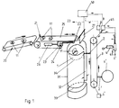
- the individual parts 11, here deep-frozen individual pretzels are fed from the left to the stacking and packaging machine via a conveyor track in the form of a driven conveyor belt 20 in the direction of the arrow.
- the feed path 20 for the individual parts 11 transfers them to the storage device 21, which can also consist of a conveyor belt or the like, the rear axis of which is preferably driven.
- the individual pieces 11 come into contact with a release plate 27 at the front end shown on the right, which triggers the storage mechanism, for example by triggering a corresponding switch contact by pivoting.
- a light barrier or the like could also be used instead.
- the deposit takes place by pulling back the right front edge of the conveyor belt, so that the piece 11, for example the pretzel, falls on the stacking plate 1 arranged below in a substantially horizontal position.
- the retraction is triggered according to FIG. 1 by a hydraulic or pneumatic system 26, which acts on the axis of a further retractable bearing 23 on the lower run of the conveyor belt 25, a further stationary bearing 24 being present.
- the conveyor belt 25 is thus guided through two fixed and two retractable bearings and is therefore always under tension.
- the hydraulics or pneumatics 26 pushes the Retracting part, the movable roller bearing 23 back to the right until the next part 11 touches the release plate 27.
- This trigger signal is simultaneously supplied to a counter 50 which an alternating signal to be stacked by individual pieces 11 provides on reaching the adjustable speed to a shift control 45 for alternate pivoting of the opposite pivot bearing 77 by 180 o.
- the pivoting can, however, only take place due to an AND control or the like if, in addition, a limit switch 4 is possibly fed to the changeover control 45 from a limit switch 4 via a further control 5, the switch contact in the uppermost position of the non-operated stacking plate 1 'or lowest position of the operating stacking plate 1 is triggered.
- this or a signal generated by the counting circuit 50 is supplied to the drive 6 for the chain 3 in order to stop the chain drive for the pivoting time and then to resume it.
- the chain drive is designed so that the stacking plate 1, 1 'is already in the lowest or highest position at the lowest adjustable number of stacks, for example 19 pieces, and remains there until the maximum number of stacks, for example 28, is reached. The falling of the individual pieces from a somewhat greater height that occurs during this phase is acceptable.
- a first stacking plate 1 is in its uppermost position at the beginning of the stacking process. Via a bearing 2 is fixed to a direction of the arrow to be driven below the chain 3, on the opposite side of the chain 3 is disposed in a lower end position, that is, by 180 o is displaced opposite a second pallet 1 'through a corresponding bearing 2' which is moved up in the same way as the storage 2 with the stacking plate 1 arranged on the left moves down during the stacking process.
- the stacking plate 1 is surrounded by a protective tube 31 so that the individual parts have a firm lateral hold and cannot fall off the stacking plate 1 even when shaking. So that a vertical movement of the stacking plate 1 is possible, this stacking tube 31 has an inner vertical slot 32 on the side of the chain 3.
- the stacking tube 31 also has a lower horizontal slot 33 and an upper horizontal slot 34.
- a limit switch with a corresponding switch contact 4 is provided on the right, which delivers a switching signal to a controller 5.
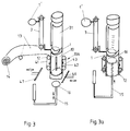
- Fig. 2 shows on the one hand in more detail the mounting of the chain 3, which is driven vertically via a driven lower roller bearing 6 'and an upper roller bearing 6.
- the roller bearings 6 and 6 'are in corresponding rotational bearings 7 and 7' are rotatably supported and may be due to an associated upper and lower rotary actuator 8 and 8 'jerky o pivoted about 180th This results in a change of the pair of stacking plates, wherein the lower stacking plate 1 after completion of 180 o to the right, and the upper stacking plate 1 '180 is o to the left or reversed alternately pivoted into the horizontal slot 34 and a new batch process can begin.
- This process is controlled by a limit switch 4 with switch contact 17, which closes a switch contact upon arrival of the right stack plate 1 ', which is not in operation, and supplies a speaking ready-to-turn switching signal to a controller 5 and the changeover controller 45.
- this signal triggers the signal together with an alternating signal supplied by the counting circuit 50 Swivel mechanism on the swivel drives 8 and 8 'and a stacking process.
- the drive of the chain 3 is controlled in a suitable manner, which must be stopped during the pivoting.
- the drive for the vertical movement of the stacking plate 1, 1 ' is disengaged during this pivoting movement in order to avoid vertical displacement.
- FIG. 3 shows the holder for the bag 12 below the stacking tube 31.
- a film web 13 is guided over rollers from a film roll 14 and wound around the holder in the form of the holding tube 10. If this holding tube 10 is completely wrapped, a vertical knife-cutting device, not shown, triggers the cutting of the film while lowering the knife.
- a connecting mechanism is then triggered, preferably by horizontally moving a welding device 43 for the two side edges of the film.
- the lower cylindrical opening is connected to one another to form a bottom, for example welded. Then the finished bag is cut off. This can be done by cooperating horizontal welding and cutting bars 46, 47 arranged below, which weld and cut off the tubular film end when the tubular film end is pressed flat.
- the supply of the film web 13 is stopped until a new stacking process has been initiated after the full bag has been filled and carried away downwards.
- paper rolls can of course also be used, the edges of which are connected in a suitable manner, e.g. are glued.
- a lifting mechanism 15 can put a punch 16 into the tubular holding device 10 from below, which can be actuated hydraulically or pneumatically via a control.
- the pushing of the punch 16 into the tube interior has the result that the stack after the jerky swiveling out of the stacking plate 1 in the lowest position cannot fall down from a considerable height and possibly break, but that it is gently collected. Then the stamp 16 is guided downwards, the full bag can be removed after it has been welded at the top, if necessary. Then the winding of a new bag 12 etc. can begin.
- the holder can also accommodate an already finished bag, which can then be attached to the lower end of the stacking tube 31.
- a drive generally designated 13A which consists of two driven conveyor belts 41, 42 arranged vertically on the holding tube 10, through which the film web 13 is guided and around it Holding tube 10 is wrapped.
- a hydraulic or pneumatic system 15 is arranged below the holding tube 16 and can push a punch 16 upwards into the interior of the holding tube 10, the entire bag on the inner wall of the holding tube 16 also being turned up to the upper end While FIG. 3 shows the state before the stamp 16 is inserted, FIG. 3a shows the upper end position of the stamp 16.
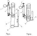
- FIG. 4 shows a simpler arrangement for filling the bag 12 in the form of a plastic bag, which is simply clamped onto the lower end of the stacking tube 31.
- the plunger 16 of the lifting mechanism 15 lifts the bottom of the bag 12 upwards without being pulled over and lowers it again after the stacking plate 1, 1 'has been pivoted out.
Landscapes
- Engineering & Computer Science (AREA)
- Mechanical Engineering (AREA)
Applications Claiming Priority (2)
| Application Number | Priority Date | Filing Date | Title |
|---|---|---|---|
| DE4141830 | 1991-12-18 | ||
| DE19914141830 DE4141830C2 (de) | 1991-12-18 | 1991-12-18 | Stapel- und Verpackungsvorrichtung für Einzelstücke |
Publications (1)
| Publication Number | Publication Date |
|---|---|
| EP0547485A1 true EP0547485A1 (fr) | 1993-06-23 |
Family
ID=6447404
Family Applications (1)
| Application Number | Title | Priority Date | Filing Date |
|---|---|---|---|
| EP92120947A Withdrawn EP0547485A1 (fr) | 1991-12-18 | 1992-12-09 | Machine pour empiler et emballer des pièces unitaires comme des petites pièces de boulangerie |
Country Status (1)
| Country | Link |
|---|---|
| EP (1) | EP0547485A1 (fr) |
Cited By (7)
| Publication number | Priority date | Publication date | Assignee | Title |
|---|---|---|---|---|
| EP1431186A3 (fr) * | 2002-12-19 | 2004-08-04 | S+R Elektroanlagen GmbH | Machine d'emballage pour des articles fragiles, plats ou en forme de disque |
| CN112407474A (zh) * | 2020-11-25 | 2021-02-26 | 广州白云山医药集团股份有限公司白云山何济公制药厂 | 一种用于散剂生产线设备的计数机构 |
| CN114248982A (zh) * | 2021-12-29 | 2022-03-29 | 中山天翔食品机械有限公司 | 一种计数装置 |
| US11465792B2 (en) * | 2018-10-25 | 2022-10-11 | And Y Knot Innovation And Sales Inc. | Stacking and packaging device |
| CN116620644A (zh) * | 2023-06-26 | 2023-08-22 | 东莞塘厦怡丰运动科技有限公司 | 一种鞋中底自动堆叠装袋打包机及其工艺 |
| CN117699423A (zh) * | 2023-12-21 | 2024-03-15 | 湖北杰精精密电子科技有限公司 | 一种电池钢壳自动码垛装置 |
| US12428245B2 (en) | 2021-08-11 | 2025-09-30 | And Y Knot Innovation And Sales Inc. | Device and conveyance system for packaging elongated items |
Citations (3)
| Publication number | Priority date | Publication date | Assignee | Title |
|---|---|---|---|---|
| DE1761948A1 (de) * | 1968-07-26 | 1971-12-23 | Thuerlings Maschf Fritz | Anordnung zum lagegerechten Einfuellen von gestapeltem Gut in senkrecht haengende Beutel |
| US3745740A (en) * | 1971-02-16 | 1973-07-17 | Scott Mach Dev Corp | Packaging method and apparatus |
| EP0104142A2 (fr) * | 1982-09-16 | 1984-03-28 | Hollymatic AG Ingenbohl | Dispositif pour déposer des objets à un endroit précis |
-
1992
- 1992-12-09 EP EP92120947A patent/EP0547485A1/fr not_active Withdrawn
Patent Citations (3)
| Publication number | Priority date | Publication date | Assignee | Title |
|---|---|---|---|---|
| DE1761948A1 (de) * | 1968-07-26 | 1971-12-23 | Thuerlings Maschf Fritz | Anordnung zum lagegerechten Einfuellen von gestapeltem Gut in senkrecht haengende Beutel |
| US3745740A (en) * | 1971-02-16 | 1973-07-17 | Scott Mach Dev Corp | Packaging method and apparatus |
| EP0104142A2 (fr) * | 1982-09-16 | 1984-03-28 | Hollymatic AG Ingenbohl | Dispositif pour déposer des objets à un endroit précis |
Cited By (9)
| Publication number | Priority date | Publication date | Assignee | Title |
|---|---|---|---|---|
| EP1431186A3 (fr) * | 2002-12-19 | 2004-08-04 | S+R Elektroanlagen GmbH | Machine d'emballage pour des articles fragiles, plats ou en forme de disque |
| DE10260014B4 (de) * | 2002-12-19 | 2005-08-11 | S & R Elektroanlagen Gmbh | Verpackungsmaschine für bruchempfindliche,flächige oder scheibenförmige Gegenstände |
| US11465792B2 (en) * | 2018-10-25 | 2022-10-11 | And Y Knot Innovation And Sales Inc. | Stacking and packaging device |
| CN112407474A (zh) * | 2020-11-25 | 2021-02-26 | 广州白云山医药集团股份有限公司白云山何济公制药厂 | 一种用于散剂生产线设备的计数机构 |
| US12428245B2 (en) | 2021-08-11 | 2025-09-30 | And Y Knot Innovation And Sales Inc. | Device and conveyance system for packaging elongated items |
| CN114248982A (zh) * | 2021-12-29 | 2022-03-29 | 中山天翔食品机械有限公司 | 一种计数装置 |
| CN116620644A (zh) * | 2023-06-26 | 2023-08-22 | 东莞塘厦怡丰运动科技有限公司 | 一种鞋中底自动堆叠装袋打包机及其工艺 |
| CN116620644B (zh) * | 2023-06-26 | 2024-06-04 | 东莞塘厦怡丰运动科技有限公司 | 一种鞋中底自动堆叠装袋打包机及其工艺 |
| CN117699423A (zh) * | 2023-12-21 | 2024-03-15 | 湖北杰精精密电子科技有限公司 | 一种电池钢壳自动码垛装置 |
Similar Documents
| Publication | Publication Date | Title |
|---|---|---|
| DE4141830C2 (de) | Stapel- und Verpackungsvorrichtung für Einzelstücke | |
| DE69603107T2 (de) | Gerät zum Zerkleinern von Lebensmitteln | |
| DE3906922C2 (fr) | ||
| DE2922930C2 (fr) | ||
| EP1260327B1 (fr) | Machine à débiter en tranches équipée d'un dispositif de coupe de film ou de papier | |
| DE2500569A1 (de) | Verpackungsmaschine | |
| DE4107669C1 (fr) | ||
| DE3006229C2 (de) | Anlage zum Sortieren und Ablegen von Blätterstapeln | |
| CH457268A (de) | Vorrichtung zum Ablegen flächenhafter Gegenstände zu einem Stapel | |
| DE2127965A1 (de) | Maschine zum erschliessen von Faltkartons mittels Klebestreifen | |
| DE2824304C2 (de) | Transportvorrichtung zum Übertragen von Faltschachtelzuschnitten von einer Druck- und Stanzmaschine zu einer Falt- und Klebemaschine | |
| DE69405307T2 (de) | Maschine zum Einwickeln von Schalen in streckbarer Folie | |
| DE69619584T2 (de) | Transportvorrichtung für metallisiertes Bahnmaterial | |
| EP0547485A1 (fr) | Machine pour empiler et emballer des pièces unitaires comme des petites pièces de boulangerie | |
| DE2423885C2 (de) | Vorrichtung zum Übergeben von Stapeln aus blattförmigen Materialzuschnitten | |
| DE4233864A1 (de) | Vorrichtung zum automatischen verbinden von baendern mit geringen querabmessungen | |
| DE2558998B2 (de) | Vorrichtung zum Schneiden einer mit einem Hohlkern versehenen Wickelrolle | |
| DE2729964B2 (de) | Vorrichtung zum automatischen Einschlagen einer mit Ware gefüllten Schale in eine Plastikfolie | |
| DE2519341C2 (de) | Vorrichtung zum Beladen mehrerer in einem Ablagegestell angeordneter Tragplatten mit blattartigen Gegenständen | |
| DE4406089C2 (de) | Vorrichtung zum Abfüllen von Tabletten oder dergleichen in Tablettenröhrchen | |
| DE2112353C3 (de) | Verfahren und Vorrichtung zum Trennen einer schuppenförmigen Folge von von einer Schlauchziehmaschine hergestellten Schlauchabschnitten für das Bilden von abgezählten Stapeln | |
| DE2600350A1 (de) | Verpackungsmaschine | |
| DE102005002532A1 (de) | Vorrichtung und Verfahren zum automatisierten und zeitgleichen Bereitstellen und Wechseln von mindestens zwei Rollen aus Papierbahnen oder dergleichen für einen nachgeordneten Formatschneider | |
| DE69801153T2 (de) | Vorrichtung zum zuführen eines filmes zu einer maschine zum verpacken von gegenständen | |
| EP1633194B1 (fr) | Procede et dispositif pour garnir des aliments |
Legal Events
| Date | Code | Title | Description |
|---|---|---|---|
| PUAI | Public reference made under article 153(3) epc to a published international application that has entered the european phase |
Free format text: ORIGINAL CODE: 0009012 |
|
| AK | Designated contracting states |
Kind code of ref document: A1 Designated state(s): AT CH DE FR IT LI NL |
|
| 17P | Request for examination filed |
Effective date: 19931221 |
|
| 17Q | First examination report despatched |
Effective date: 19950221 |
|
| STAA | Information on the status of an ep patent application or granted ep patent |
Free format text: STATUS: THE APPLICATION IS DEEMED TO BE WITHDRAWN |
|
| 18D | Application deemed to be withdrawn |
Effective date: 19950627 |