EP0547632A1 - Verschiebbares Zahnrad - Google Patents
Verschiebbares Zahnrad Download PDFInfo
- Publication number
- EP0547632A1 EP0547632A1 EP92121633A EP92121633A EP0547632A1 EP 0547632 A1 EP0547632 A1 EP 0547632A1 EP 92121633 A EP92121633 A EP 92121633A EP 92121633 A EP92121633 A EP 92121633A EP 0547632 A1 EP0547632 A1 EP 0547632A1
- Authority
- EP
- European Patent Office
- Prior art keywords
- gear
- teeth
- shaft
- sliding
- gears
- Prior art date
- Legal status (The legal status is an assumption and is not a legal conclusion. Google has not performed a legal analysis and makes no representation as to the accuracy of the status listed.)
- Withdrawn
Links
Images


Classifications
-
- F—MECHANICAL ENGINEERING; LIGHTING; HEATING; WEAPONS; BLASTING
- F16—ENGINEERING ELEMENTS AND UNITS; GENERAL MEASURES FOR PRODUCING AND MAINTAINING EFFECTIVE FUNCTIONING OF MACHINES OR INSTALLATIONS; THERMAL INSULATION IN GENERAL
- F16H—GEARING
- F16H1/00—Toothed gearings for conveying rotary motion
- F16H1/02—Toothed gearings for conveying rotary motion without gears having orbital motion
- F16H1/04—Toothed gearings for conveying rotary motion without gears having orbital motion involving only two intermeshing members
-
- F—MECHANICAL ENGINEERING; LIGHTING; HEATING; WEAPONS; BLASTING
- F16—ENGINEERING ELEMENTS AND UNITS; GENERAL MEASURES FOR PRODUCING AND MAINTAINING EFFECTIVE FUNCTIONING OF MACHINES OR INSTALLATIONS; THERMAL INSULATION IN GENERAL
- F16H—GEARING
- F16H55/00—Elements with teeth or friction surfaces for conveying motion; Worms, pulleys or sheaves for gearing mechanisms
- F16H55/02—Toothed members; Worms
- F16H55/08—Profiling
- F16H55/0873—Profiling for improving axial engagement, e.g. a chamfer at the end of the tooth flank
-
- F—MECHANICAL ENGINEERING; LIGHTING; HEATING; WEAPONS; BLASTING
- F16—ENGINEERING ELEMENTS AND UNITS; GENERAL MEASURES FOR PRODUCING AND MAINTAINING EFFECTIVE FUNCTIONING OF MACHINES OR INSTALLATIONS; THERMAL INSULATION IN GENERAL
- F16H—GEARING
- F16H3/00—Toothed gearings for conveying rotary motion with variable gear ratio or for reversing rotary motion
- F16H3/02—Toothed gearings for conveying rotary motion with variable gear ratio or for reversing rotary motion without gears having orbital motion
- F16H3/20—Toothed gearings for conveying rotary motion with variable gear ratio or for reversing rotary motion without gears having orbital motion exclusively or essentially using gears that can be moved out of gear
- F16H3/22—Toothed gearings for conveying rotary motion with variable gear ratio or for reversing rotary motion without gears having orbital motion exclusively or essentially using gears that can be moved out of gear with gears shiftable only axially
-
- F—MECHANICAL ENGINEERING; LIGHTING; HEATING; WEAPONS; BLASTING
- F16—ENGINEERING ELEMENTS AND UNITS; GENERAL MEASURES FOR PRODUCING AND MAINTAINING EFFECTIVE FUNCTIONING OF MACHINES OR INSTALLATIONS; THERMAL INSULATION IN GENERAL
- F16H—GEARING
- F16H55/00—Elements with teeth or friction surfaces for conveying motion; Worms, pulleys or sheaves for gearing mechanisms
- F16H55/02—Toothed members; Worms
- F16H55/17—Toothed wheels
Definitions
- This invention generally relates to a sliding gear in which a gear slides along its axe so as to place itself in or out of engagement with its mating gears, and more particularly to a sliding gear in which outer teeth of the gears engage with one another.
- a transmission for a motor vehicle includes gear trains in which speed changes are made by changing a rotational force, received at an input shaft, to a desired rotational force at a predetermined transmission ratio so as to be transmitted from an output shaft.
- gear trains a sliding gear is mainly used to transmit a reverse rotational force. Receiving the rotational force, the sliding gear slides along its axe, engages with its mating gear, reverse the received rotational force, and transmits the reversed force to another mating gear.
- an idler gear 1 as the sliding gear engages with and disengages from an input gear 3 on an input shaft 2 and a reverse gear 5 on a reverse operating shaft 4.
- the idler gear 1 slides along its axe, i.e. in the rotational direction X, in response to a speed changing operation, and contacts with side edges of the gears 3 and 5 on the input and output shafts.
- teeth on the outer peripheral surface (hereinafter called "outer teeth) of the idler gear 1 contact with outer teeth of the input gear 3 at a plurality of points D (refer to Fig. 5).
- the gears With the engagement between the inner teeth and the outer teeth of the gears, the gears shift with their center lines A2 and a2 kept parallel with one another, so that the gears can smoothly engage with one another.
- the synchronizing unit comprises a spline gear fitted on a sleeve.
- the spline gear has teeth which are divided into those engageable with a synchronization ring and those engageable with a dog tooth gear.
- the teeth of the gears have different chamfer angles depending upon the synchronization ring and the dog tooth gear to be engaged with.
- the sliding gear comprises a first gear having teeth on its outer peripheral surface and fitted on a first shaft, an auxiliary shaft in parallel with the first shaft, and a sliding gear fitted on the auxiliary shaft, which has teeth on its outer surface, and is axially slidable on the auxiliary shaft so as to be engageable with the first gear.
- a part of teeth of the first gear and/or the sliding gear is smaller than the other teeth in the width. Therefore, the point D where the gears contact with one another can be relatively reduced compared with conventional sliding gears.
- Fig. 1 is a front view, a partly cutaway view, of a main part of a sliding gear according to a first embodiment of the invention.
- Fig. 2 is a side sectional view, a partly cutaway view, of the sliding gear and an input gear.
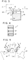
- Fig. 3 is a view similar to Fig. 1 showing a sliding gear according to a second embodiment.
- Fig. 4 is a front view, a partly cutaway view, of a main part of a conventional sliding gear having teeth on the outer peripheral surface thereof.
- Fig. 5 is a side sectional view of the conventional sliding gear of Fig. 4 and an input gear.
- Fig. 6 is a sectional view of a main part of a gear train having the conventional sliding gear of Fig. 4.
- Fig. 7 is a sectional view of a main part of a sliding gear having teeth on the inner peripheral surface thereof.
- the sliding gear 10 can be used in place of the idler gear 1 of the transmission shown in Fig. 6.
- the sliding gear 10 is engageable with and disengageable from a gear 3 of an input shaft 2 and a reverse gear 5 of a reverse operating shaft 4.
- All of the sliding gear 10, input gear 3 and reverse gear 5 are spur gears.
- the input gear 3 and the reverse gear 5 have teeth 301 and 501 on their outer peripheral surfaces.
- the teeth 301 and 501 have the same width B1.
- the sliding gear 10 have teeth 11a and 11b alternately formed on its outer peripheral surface.
- the teeth 11a have a width B2, while the teeth 11b have a width B3.
- the teeth 11a and the teeth 11b are bevelled by a rake angle (represented by ⁇ 1 or ⁇ 2 in Fig. 3) at one side edge S of the sliding gear 10, so that chamfers f1 and f2 will be formed.
- the teeth 11a have the width B2 which is substantially equal to the face width of the sliding gear 10.
- the teeth 11b are shorter than the teeth 11a by a predetermined amount c .
- the width B3 of the teeth 11b is substantially equal to (B2 - c).
- the sliding gear 10 has the teeth 11a with the chambers f1 and the teeth 11b with the chamfers f2.
- the teeth 11a and 11b are alternately formed on the sliding gear 10 as described above.
- the teeth 301 of the input gear 3 are bevelled by a predetermined rake angle at the side edge S' of the input gear 3, thereby forming chamfers f3.
- the side edge S' of the input gear 3 confront the side edge S of the spur gear 10.
- the teeth 501 of the counter gear 5 are also bevelled in the similar manner to the teeth 301 of the input gear 3.
- a chamfer f1 of a tooth 11a of the sliding gear 10 comes into contact with a chamfer f3 of the gear 3 or the gear 5 (at the point D shown in Fig. 3).
- the chamfer f2 of the tooth 11b adjacent to the foregoing tooth 11a stays by the predetermined distance c away from the chamfers f3 of the gears 3 and 5. (In other words, the chamfer f2 is not in contact with the chamfer f3 at the point C in Fig. 2.)
- a sliding gear according to a second embodiment will be described hereinafter.
- a sliding gear 10a has outer teeth 11c and 11d which have the same width but have chamfers f4 and f5, which are bevelled with different angles ⁇ 1 and ⁇ 2 at the side edge S'' of the sliding gear 10a.
- the angle ⁇ 2 is larger than the angle ⁇ 1.
- These teeth 11c and 11d are alternately formed on the sliding gear 10a.
- the sliding gear 10a comes into alternate contact with the input gear 3 or the reverse gear 5 at one point D. Therefore, these gears contact with one another with a relatively small frictional resistance, and can engage with one another after their rotations.
- the sliding gears 10 and 10a are described assuming that they are applied to the transmission of the motor vehicle. These gears are also applicable to gear trains for a transfer system or the like.
- the sliding gears have the teeth whose edges are bevelled, the teeth of the input gear or the reverse gear can be designed to have bevelled edges.
- the sliding gear having the teeth with differently bevelled edges contacts with its mating gears at a reduced number of points and smoothly engages with them.
Landscapes
- Engineering & Computer Science (AREA)
- General Engineering & Computer Science (AREA)
- Mechanical Engineering (AREA)
- Gears, Cams (AREA)
- Gear Transmission (AREA)
- Structure Of Transmissions (AREA)
Applications Claiming Priority (2)
| Application Number | Priority Date | Filing Date | Title |
|---|---|---|---|
| JP336778/91 | 1991-12-19 | ||
| JP3336778A JPH05172191A (ja) | 1991-12-19 | 1991-12-19 | スライディングギア |
Publications (1)
| Publication Number | Publication Date |
|---|---|
| EP0547632A1 true EP0547632A1 (de) | 1993-06-23 |
Family
ID=18302610
Family Applications (1)
| Application Number | Title | Priority Date | Filing Date |
|---|---|---|---|
| EP92121633A Withdrawn EP0547632A1 (de) | 1991-12-19 | 1992-12-18 | Verschiebbares Zahnrad |
Country Status (3)
| Country | Link |
|---|---|
| EP (1) | EP0547632A1 (de) |
| JP (1) | JPH05172191A (de) |
| KR (1) | KR960008786B1 (de) |
Cited By (11)
| Publication number | Priority date | Publication date | Assignee | Title |
|---|---|---|---|---|
| EP0955486A1 (de) * | 1998-04-18 | 1999-11-10 | Ford Global Technologies, Inc., A subsidiary of Ford Motor Company | Umkehr-Schieberad-Anordnung fuer ein Wechselgetriebe |
| EP1045170A1 (de) | 1999-04-15 | 2000-10-18 | Ford Global Technologies, Inc., A subsidiary of Ford Motor Company | Umkehr-Schieberad-Anordnung für ein Wechselgetriebe |
| EP1045171A1 (de) | 1999-04-15 | 2000-10-18 | Ford Global Technologies, Inc., A subsidiary of Ford Motor Company | Umkehr-Schieberad-Anordnung für ein Wechselgetriebe |
| EP1172584A1 (de) | 2000-06-19 | 2002-01-16 | Ford Global Technologies, Inc., A subsidiary of Ford Motor Company | Schiebezahnradsatz |
| DE19951787B4 (de) * | 1998-10-27 | 2013-02-28 | New Venture Gear, Inc. | Getriebe |
| CN103047391A (zh) * | 2012-12-24 | 2013-04-17 | 徐成金 | 组合齿轮 |
| CN104358832A (zh) * | 2014-10-30 | 2015-02-18 | 王洋 | 一种防对死水平啮合齿轮组及双向啮合搬运平台 |
| EP2798944A3 (de) * | 2013-05-01 | 2015-03-18 | CNH Industrial Belgium nv | Verfahren zur Fernkonfiguration eines Restesystem einer landwirtschaftlichen Erntemaschine |
| WO2017089088A1 (de) * | 2015-11-23 | 2017-06-01 | Bayerische Motoren Werke Aktiengesellschaft | Schrägverzahnung mit verändertem zahneingriff |
| US10436169B2 (en) | 2008-12-19 | 2019-10-08 | Seg Automotive Germany Gmbh | Method and device for start-stop systems of internal combustion engines in motor vehicles |
| NL2023882B1 (nl) * | 2019-09-23 | 2021-05-25 | Mci Mirror Controls Int Netherlands B V | Tandwielsamenstel |
Families Citing this family (1)
| Publication number | Priority date | Publication date | Assignee | Title |
|---|---|---|---|---|
| DE19721568B4 (de) * | 1996-05-31 | 2005-09-01 | Volkswagen Ag | Schrägverzahntes Zahnrad mit variabler Zahnlänge |
Citations (4)
| Publication number | Priority date | Publication date | Assignee | Title |
|---|---|---|---|---|
| AT2756B (de) * | 1899-06-20 | 1900-11-26 | Motorfahrzeug Und Motorenfabri | |
| DE387734C (de) * | 1917-07-07 | 1924-01-05 | Automobilwerke H Buessing Ag | Zahnraederwechselgetriebe |
| DE1214966B (de) * | 1961-10-31 | 1966-04-21 | Siemens Ag | Schieberadgetriebe, insbesondere fuer feinmechanische Geraete |
| FR1492988A (fr) * | 1966-07-11 | 1967-08-25 | Moyse S A | Engrenages pour changement de vitesse à l'arrêt |
Family Cites Families (2)
| Publication number | Priority date | Publication date | Assignee | Title |
|---|---|---|---|---|
| JPS61110428A (ja) * | 1984-11-02 | 1986-05-28 | Canon Inc | 半導体焼付装置 |
| JPS62139958A (ja) * | 1985-12-13 | 1987-06-23 | Mitsubishi Heavy Ind Ltd | ボイルオフガスの供給方法及びその装置 |
-
1991
- 1991-12-19 JP JP3336778A patent/JPH05172191A/ja active Pending
-
1992
- 1992-12-17 KR KR92024612A patent/KR960008786B1/ko not_active Expired - Fee Related
- 1992-12-18 EP EP92121633A patent/EP0547632A1/de not_active Withdrawn
Patent Citations (4)
| Publication number | Priority date | Publication date | Assignee | Title |
|---|---|---|---|---|
| AT2756B (de) * | 1899-06-20 | 1900-11-26 | Motorfahrzeug Und Motorenfabri | |
| DE387734C (de) * | 1917-07-07 | 1924-01-05 | Automobilwerke H Buessing Ag | Zahnraederwechselgetriebe |
| DE1214966B (de) * | 1961-10-31 | 1966-04-21 | Siemens Ag | Schieberadgetriebe, insbesondere fuer feinmechanische Geraete |
| FR1492988A (fr) * | 1966-07-11 | 1967-08-25 | Moyse S A | Engrenages pour changement de vitesse à l'arrêt |
Cited By (16)
| Publication number | Priority date | Publication date | Assignee | Title |
|---|---|---|---|---|
| EP0955486A1 (de) * | 1998-04-18 | 1999-11-10 | Ford Global Technologies, Inc., A subsidiary of Ford Motor Company | Umkehr-Schieberad-Anordnung fuer ein Wechselgetriebe |
| DE19951787B4 (de) * | 1998-10-27 | 2013-02-28 | New Venture Gear, Inc. | Getriebe |
| EP1045170A1 (de) | 1999-04-15 | 2000-10-18 | Ford Global Technologies, Inc., A subsidiary of Ford Motor Company | Umkehr-Schieberad-Anordnung für ein Wechselgetriebe |
| EP1045171A1 (de) | 1999-04-15 | 2000-10-18 | Ford Global Technologies, Inc., A subsidiary of Ford Motor Company | Umkehr-Schieberad-Anordnung für ein Wechselgetriebe |
| EP1172584A1 (de) | 2000-06-19 | 2002-01-16 | Ford Global Technologies, Inc., A subsidiary of Ford Motor Company | Schiebezahnradsatz |
| US10436169B2 (en) | 2008-12-19 | 2019-10-08 | Seg Automotive Germany Gmbh | Method and device for start-stop systems of internal combustion engines in motor vehicles |
| CN103047391A (zh) * | 2012-12-24 | 2013-04-17 | 徐成金 | 组合齿轮 |
| EP2798944A3 (de) * | 2013-05-01 | 2015-03-18 | CNH Industrial Belgium nv | Verfahren zur Fernkonfiguration eines Restesystem einer landwirtschaftlichen Erntemaschine |
| US9107345B2 (en) | 2013-05-01 | 2015-08-18 | Cnh Industrial America Llc | Method of remotely configuring a residue system of an agricultural harvester |
| US9462751B2 (en) | 2013-05-01 | 2016-10-11 | Cnh Industrial America Llc | Method of remotely configuring a residue system of an agricultural harvester |
| CN104358832A (zh) * | 2014-10-30 | 2015-02-18 | 王洋 | 一种防对死水平啮合齿轮组及双向啮合搬运平台 |
| WO2017089088A1 (de) * | 2015-11-23 | 2017-06-01 | Bayerische Motoren Werke Aktiengesellschaft | Schrägverzahnung mit verändertem zahneingriff |
| CN107923512A (zh) * | 2015-11-23 | 2018-04-17 | 宝马股份公司 | 具有改变的齿接合的斜齿部 |
| US10907720B2 (en) | 2015-11-23 | 2021-02-02 | Bayerische Motoren Werke Aktiengesellschaft | Helical tooth system having modified tooth meshing |
| CN107923512B (zh) * | 2015-11-23 | 2021-02-09 | 宝马股份公司 | 具有改变的齿接合的斜齿部 |
| NL2023882B1 (nl) * | 2019-09-23 | 2021-05-25 | Mci Mirror Controls Int Netherlands B V | Tandwielsamenstel |
Also Published As
| Publication number | Publication date |
|---|---|
| JPH05172191A (ja) | 1993-07-09 |
| KR930013528A (ko) | 1993-07-22 |
| KR960008786B1 (en) | 1996-07-03 |
Similar Documents
| Publication | Publication Date | Title |
|---|---|---|
| EP0547632A1 (de) | Verschiebbares Zahnrad | |
| US4727968A (en) | Synchronizer clutch assembly | |
| US4905806A (en) | Synchronizing shift clutch toothing arrangement | |
| US5135087A (en) | Dual-cone synchronizer with servo action | |
| US4573371A (en) | Auxiliary power transmission having synchronizing mechanism | |
| US4641734A (en) | Synchronizing mechanism for clutches | |
| US4181210A (en) | Clutch with interlocking teeth | |
| EP0444785B1 (de) | Zahnrad-Kupplung | |
| JPS63158329A (ja) | 同期噛合装置 | |
| CA1289089C (en) | Synchronizer means for change speed gear boxes, particularly for motor vehicles | |
| US4922767A (en) | Helical gear transmission device | |
| GB1096814A (en) | Toothed members | |
| US3219164A (en) | Transmission lock | |
| GB2065800A (en) | Synchronizer for motor vehicle gearboxes | |
| US3477250A (en) | Anchor tooth spline for rotating gear mechanisms | |
| US4280370A (en) | Clutch assembly for gear-type transmission system | |
| JPH07190093A (ja) | 歯車変速機の噛合装置 | |
| GB2134607A (en) | Coupling arrangement particularly for a marine drive | |
| EP0976942B1 (de) | Sychronisierte Kupplung für ein Fahrzeuggetriebe | |
| JPS6218770B2 (de) | ||
| JPH07190092A (ja) | 歯車変速機の噛合装置 | |
| US2579090A (en) | Synchronizing mechanism | |
| US3197000A (en) | Synchronizer assembly | |
| GB2188696A (en) | Torque limiting and overtravel stop device | |
| US2275718A (en) | Synchronized low gear |
Legal Events
| Date | Code | Title | Description |
|---|---|---|---|
| PUAI | Public reference made under article 153(3) epc to a published international application that has entered the european phase |
Free format text: ORIGINAL CODE: 0009012 |
|
| AK | Designated contracting states |
Kind code of ref document: A1 Designated state(s): DE FR GB IT NL |
|
| 17P | Request for examination filed |
Effective date: 19930709 |
|
| 17Q | First examination report despatched |
Effective date: 19950510 |
|
| STAA | Information on the status of an ep patent application or granted ep patent |
Free format text: STATUS: THE APPLICATION IS DEEMED TO BE WITHDRAWN |
|
| 18D | Application deemed to be withdrawn |
Effective date: 19960827 |