EP0547638A1 - Outil de vissage - Google Patents
Outil de vissage Download PDFInfo
- Publication number
- EP0547638A1 EP0547638A1 EP92121652A EP92121652A EP0547638A1 EP 0547638 A1 EP0547638 A1 EP 0547638A1 EP 92121652 A EP92121652 A EP 92121652A EP 92121652 A EP92121652 A EP 92121652A EP 0547638 A1 EP0547638 A1 EP 0547638A1
- Authority
- EP
- European Patent Office
- Prior art keywords
- holding
- clamping
- fastening element
- fastening
- head
- Prior art date
- Legal status (The legal status is an assumption and is not a legal conclusion. Google has not performed a legal analysis and makes no representation as to the accuracy of the status listed.)
- Granted
Links
Images


Classifications
-
- B—PERFORMING OPERATIONS; TRANSPORTING
- B25—HAND TOOLS; PORTABLE POWER-DRIVEN TOOLS; MANIPULATORS
- B25B—TOOLS OR BENCH DEVICES NOT OTHERWISE PROVIDED FOR, FOR FASTENING, CONNECTING, DISENGAGING, OR HOLDING
- B25B23/00—Details of, or accessories for, spanners, wrenches, screwdrivers
- B25B23/02—Arrangements for handling screws or nuts
- B25B23/08—Arrangements for handling screws or nuts for holding or positioning screw or nut prior to or during its rotation
- B25B23/10—Arrangements for handling screws or nuts for holding or positioning screw or nut prior to or during its rotation using mechanical gripping means
-
- B—PERFORMING OPERATIONS; TRANSPORTING
- B23—MACHINE TOOLS; METAL-WORKING NOT OTHERWISE PROVIDED FOR
- B23P—METAL-WORKING NOT OTHERWISE PROVIDED FOR; COMBINED OPERATIONS; UNIVERSAL MACHINE TOOLS
- B23P19/00—Machines for simply fitting together or separating metal parts or objects, or metal and non-metal parts, whether or not involving some deformation; Tools or devices therefor so far as not provided for in other classes
- B23P19/001—Article feeders for assembling machines
- B23P19/006—Holding or positioning the article in front of the applying tool
-
- B—PERFORMING OPERATIONS; TRANSPORTING
- B25—HAND TOOLS; PORTABLE POWER-DRIVEN TOOLS; MANIPULATORS
- B25B—TOOLS OR BENCH DEVICES NOT OTHERWISE PROVIDED FOR, FOR FASTENING, CONNECTING, DISENGAGING, OR HOLDING
- B25B23/00—Details of, or accessories for, spanners, wrenches, screwdrivers
- B25B23/02—Arrangements for handling screws or nuts
- B25B23/04—Arrangements for handling screws or nuts for feeding screws or nuts
-
- B—PERFORMING OPERATIONS; TRANSPORTING
- B25—HAND TOOLS; PORTABLE POWER-DRIVEN TOOLS; MANIPULATORS
- B25C—HAND-HELD NAILING OR STAPLING TOOLS; MANUALLY OPERATED PORTABLE STAPLING TOOLS
- B25C1/00—Hand-held nailing tools; Nail feeding devices
- B25C1/08—Hand-held nailing tools; Nail feeding devices operated by combustion pressure
- B25C1/10—Hand-held nailing tools; Nail feeding devices operated by combustion pressure generated by detonation of a cartridge
- B25C1/18—Details and accessories, e.g. splinter guards, spall minimisers
- B25C1/188—Arrangements at the forward end of the barrel, e.g. splinter guards, spall minimisers, safety arrangements, silencers, bolt retainers
Definitions
- the invention relates to a screwing device.
- Screwing devices are already known. They contain a motor drive with which a screw can be driven and screwed in. The screws are inserted through a feed tube and fall to a holding head, which is arranged in the lower area of the device. The screws are held there. The user presses the drive down until it engages the screw head with a tool and screws in the screw.
- the screw is held by two holding elements arranged at the same axial position, which form a cylindrical passage between them. Since the screws to be screwed in are normally screws with a drill head and adjoining side wings, only screws can be processed with such a device in which the distance between the screw head and the wings is greater than the length of the holding elements.
- the holding elements grip like this that the screw gets stuck on the top of the holding elements. This means that it is aligned with the head of the screw.
- the invention has for its object to provide an easy-to-use device for driving a fastener in which only a short driving movement is required and in which fasteners of a very wide range of dimensions can still be used without change.
- the invention proposes a device with the features of claim 1. Further training is the subject of the subclaims.
- fastening element By holding the fastening element at two locations that are spaced apart from one another, better fastening of the fastening element and better guidance in the longitudinal direction is made possible.
- the fastening element remains aligned even when the drive starts, but the fastening element is not yet guided in the part to be fastened.
- the fastening element is aligned in the region of its front end.
- the front end is the end of the fastener that first engages the part into which it is to be driven. So the front end of a screw is the end with the screw tip. In this way, even with fasteners of very different lengths, it can always be ensured that the tip is held at a certain short distance from the surface into which the fastener is to be driven. This means that the drive-in distance is always as short as possible.
- At least one, preferably two, laterally movable holding jaws are provided for gripping the tip of the fastening element, which are in particular designed to be pivotable.
- the holding jaws in the closed state the holding jaws leave an opening between them which can be aligned axially with respect to the device and in which the tip of the fastening element is held.
- the fastening element can thus center itself between the two holding jaws, so that the holding jaws need not have any clamping action if the appropriate design is used.
- the holder has a tubular element which surrounds the fastening element and in particular its head. Because of the mounting at two points apart from one another, it becomes possible to carry out the mounting of the fastening element in the head region only approximately, so that there can be a certain radial distance here.
- the tubular element can, for example, have a circular inner cross section which is larger than the maximum transverse dimension of the head of the fastening element.
- fastening elements of different transverse dimensions can certainly be used. Possibly. can also be provided if fastening elements of very different dimensions are to be used to replace the tubular element.
- a second tubular element is inserted into a tubular configuration of the holder.
- the tubular element can be inserted and / or removed from the underside of the device. In this way, the conversion for another fastener can be carried out very easily and very quickly.
- the insertable or interchangeable tubular element can be provided according to the invention to hold the tubular element in a latching manner.
- balls under spring loading can be provided which engage in corresponding recesses in the tubular element.
- the tubular element engages from above between the holding jaws.
- the holder has at least two clamping elements which act against the fastening element in a closed position and are at least partially movable independently of one another.
- the possibility of moving both clamping elements independently of one another in at least a certain area makes use possible even with complicated shapes of the fastening elements, for example with the above-mentioned, winged screws.
- the clamping elements are guided such that when the clamping element for the tip of the fastening element is closed, the other clamping element is at least partially open.
- the fasteners are moved downwards by the feed device in the normal case, that is, they fall down, in this way it is ensured that the tip of the fastener falls through the location of the slightly open upper clamping element and is only held by the lower clamping element. The same applies, of course, when working in a different direction.
- a radial distance between the fastening element and the holding device is provided in the area between the clamping points.
- the two clamping devices open one after the other when driving in the fastening element.
- the invention proposes that at least one clamping device can be formed by at least one clamping jaw, which moves essentially radially.
- the clamping elements of the holder can advantageously be acted upon by springs.
- the feed device for feeding the fastening elements has a magazine for them. This enables the user, for example, to screw a whole row of boards onto the floor without having to put the device down between the screwing operations and without having to push in a fastening element.
- the magazine is designed such that it loosely receives the fastening elements.
- the invention provides that the magazine or the feed device has a separating device for the fastening elements, which is switched on when the fastening element is driven in. This can advantageously be done in a two-stage process. When the drive is advanced, the foremost screw is separated from the others and released when the drive is pulled back so that it falls through the feed device to the holding head.
- the feed device has the possibility of entering a single fastening element bypassing the magazine.
- the device proposed by the invention is particularly suitable for screwing in screws.
- the drive has a screwdriver drive with a clutch which can be engaged by the counterpressure generated when the screw is screwed in.
- the motor of this screwdriver drive runs constantly, while the tool it drives is only driven under counter pressure. This only makes it possible for the tool to penetrate the screw head recess in a reasonable manner.
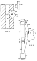
- a guide tube 4 is screwed to the rectilinear upper end of the neck tube 1 opposite the holding head 3 via an adapter piece (not shown in detail), on the outside of which a stop nut 5 is provided.
- a drive arrangement 6 is displaceable on the guide tube 4 between two end positions, see in particular FIG. 2.
- the drive arrangement 6 contains an outer sleeve 7 which is placed on the guide tube 4 and slides telescopically thereon. At the upper end, the outer sleeve 7 is connected to a clamping piece 8, which serves to receive the actual drive (not shown in the figures) and to attach a handle 9.
- a drive shaft 10, which is located in Extends longitudinally through the screwing device and at the lower end of which a drive tool 11 is attached. It can be a standard screwdriver bit.
- the displaceability of the drive arrangement 6 is limited by stops, the lower position being able to be finely adjusted by the abovementioned stop nut 5 shown in FIG. 1.
- a charging housing 12 is fastened in its upper region to the inlet connection 2 forming the branch.
- the feed housing 12 contains a downward-facing passage 13, which is arranged in the extension of the inlet connector 2 and through which a fastening element, for example a screw, can fall to the holding head 3.
- a magazine 14 is fastened to the side of the loading housing 12 and essentially consists of two magazine plates which run parallel to one another and form an intermediate space between them. These magazine plates can be flat, so that they extend laterally, or they can also be curved so that the magazine 14 as a whole extends around the device.
- the two plates forming the magazine 14 have an upper edge 15 which run obliquely downwards in the direction of the passage 13 of the loading housing 12.
- a separating device 16 is arranged on the end of the magazine 14 facing the loading housing 12 and has a blocking element 17 which can be pivoted about a horizontal axis.
- the locking element has two lugs 18, 19, of which the lug 18 closer to the passage 13 can be seen in FIG. 1.
- a prestressing sleeve 20 surrounding the drive shaft 10 is fastened within the guide tube 4 and has an outer shoulder 21 in the region of its end face facing the drive.
- An indicated compression spring 22 is supported on this shoulder, the other end of which rests on the drive. The strength of the Spring 22 is selected so that the drive is moved by this spring in the upper end position, which is shown in Fig. 1.
- the screw-in device described so far is operated as follows.
- the user places the device on the corresponding surface at a point where he wants to screw in a screw.
- a fastening element for example a screw
- a fastening element is dropped down through the passage 13 of the feed housing 12, arrives there in the holding head 3 and is held there by the holding elements to be described at two spaced-apart locations.
- the user uses the handle 9 to press the drive device 6 down until the tool 11 engages in the recess of the screw head. If he now presses the handle 9 further down, the holding elements and / or the impact of the tip of the screw on the surface creates a counterpressure which leads to the engagement of a clutch arranged in the drive.
- the tool 11 which has engaged in the recess of the screw head, is rotated and screwed in the screw. After this is screwed in, which the user can determine by the outer sleeve 7 resting on the stop nut 5, the user interrupts the feed movement and allows the drive to return to the starting position under the influence of the spring 22. Then a new fastener can fall into the holding head 3.
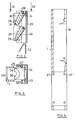
- Fig. 3 shows a longitudinal section through a jaw holder 23 for holding two clamping jaws 24, 25.
- the holding head 3 of Fig. 1 contains two such jaw holders 23 arranged symmetrically to the longitudinal axis of the device and to the longitudinal axis of the screw to be fastened.
- Fig. 4 shows a section approximately along line IV-IV in Fig. 3 through the jaw holder. This is designed as an approximately U-shaped profile, the two legs 26 of which are provided with fastening holes 27 for fastening to the neck tube 1 are. Shafts 28 extend between the legs 26 and serve as axes for the two clamping jaws 24, 25.
- Both clamping jaws are of similar design and contain a lower section in which a short channel-like clamping section 29 is formed. Above the clamping sections 29, the sides 30 of the clamping jaws 24, 25 directed towards the radial inside expand in a funnel-like manner.
- the lower clamping jaw 25 has a projection 31 in the region of its upper end, with which it engages on the inside of the clamping section 29 of the upper jaw 24. If the lower jaw 25 is pivoted clockwise into its closed position shown in FIG. 3, the projection 31 pushes the upper jaw 24 counterclockwise by a small amount, so that this jaw 24 is not in the fully closed position.
- a fastening element falling from top to bottom for example a screw, falls freely past the upper clamping jaws 24 until its tip is held on the clamping point 29 of the lower jaw.
- the fastener is always aligned at its tip, so that the distance of the tip of the fastener from the underside of the neck tube 1 is always the same and thus the screwing-in path is always the same.
- leaf springs 32 are used, which are inserted between the inside of the jaw holder 23 and the outside 33 of the jaws. They can be welded to the jaw holder, for example, on one leg.
- FIG. 4 shows the upper jaw 24 in supervision. It can be seen that a funnel 30 is actually formed here, if one takes into account that an identical arrangement is applied in mirror image from the other side.
- the mutual alignment between the jaw holder 23 and the neck tube 1 also results from FIG. 4, which shows the neck tube 1 schematically indicates correct positioning.
- the closed position of the two jaws is defined by the fact that the end faces 34 of the jaws lying in one diameter abut one another.
- FIG. 5 shows on the same scale as Figs. 3 and 4, a longitudinal section through the neck tube 1 with the insertion tube removed.
- the neck tube 1 has a rectangular or square cross section and contains an opening 35 on the side for inserting the insertion socket 2 and an opening 36 for the two jaw holders 23 in the lower region.
- FIG. 5 shows the holes 27 corresponding to the holes 27 in the side walls of the neck tube Holes 37.
- Fig. 6 shows a longitudinal section through the insertion nozzle 2, the function of which can be seen from Fig. 1.
- the insertion piece is inserted through the mentioned opening 35 into the neck tube and screwed there.
- a shoulder 38 is formed on the insertion nozzle 2, to which the connecting strap 39 shown in FIG. 10 can be screwed.
- the connecting tab 39 not only has holes for screwing onto the attachment 38, but also for screwing onto the loading housing 12 of FIG. 8. The further holes of the connecting tab 39 serve to screw the magazine 14 in place.
- an oval opening 40 is formed on the side next to the passage 13 in the upper region, in which the locking element 17, see FIG. 11, can be used.
- the locking element 17 has two lugs 18, 19 which are at a distance from one another which essentially corresponds to the diameter of a fastening element, for example a screw. One of the two lugs engages behind the last fastening element and the other behind the penultimate fastening element, as will be shown below.
- Fig. 9 shows a view of the loading housing of Fig. 8 from the right. It can be seen here that a recess 41 is formed on both sides for the connecting strap 39.
- the feed housing 12 includes a longitudinally extending slot 42, the width of which is slightly larger than a fastener. On both sides of the slot 12 holes 47 are arranged in the side edge 43 of the feed housing. One of these holes 44 serves to receive an axis about which the locking element 17 can pivot.
- Fig. 7 shows the top view of the insertion nozzle, it can be seen again that the insertion nozzle is attached to a neck tube which is rectangular in cross section.
- the locking element 17 is arranged to be pivotable about an axis passing through a hole 44.
- the locking element has two stable end positions, of which FIG. 12 represents one. In this end position, a nose 18 engages in the slot 42 of the loading housing. A fastening element lying in front of the nose 18 is prevented by the nose 18 from sliding into the passage 3 of the feed housing 12. If the device is now operated by screwing in a screw, a pin 46 attached to an actuating plate 45 comes to rest against a cam surface 47 of the locking element 17. When it is in contact and pushed further, the pin 46 pivots the locking element clockwise by an angle of approximately 45 °, so that the nose 18 is moved out of the slot 42.
- Fig. 13 shows the arrangement of the pin 46 at the lower end of the actuating plate 45, which in turn is fixed to a clamp 48 on the outer sleeve 7. A fine adjustment can be done with the help of a longitudinal slot 49. The next fastener is always released when it moves upwards, since the fastener then has sufficient time to fall to the holding head.
- the effect of the stop nut 5, which limits the downward displacement of the outer sleeve 7, can be seen again from FIG. 13.
- the stop nut 5 can be adjusted very finely due to its threaded connection with the neck tube 1 or the guide tube 4, so that there is a precise stop.
- a stop can be attached to the holding head 3, in order, if necessary, to adjust the distance between the underside 49 of the neck tube 1 and the surface on which screwing is to be carried out.
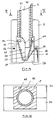
- the screwing device shown in FIGS. 14 and 15 contains, in the region of the lower end of its neck tube 1, a holding head 3 which is intended for holding the fastening elements, in particular screws.
- the neck tube 1 has an inner opening 50 with a circular cross section, see also FIG. 15.
- the holding head 3 is fastened to the outside of the neck tube 1. It can consist, for example, of two parts 3a, 3b which are divided along a central plane and which can be screwed together.
- the holding head 3 contains a widened inner opening 51 in which two holding jaws 52 can be pivoted are stored.
- the two holding jaws 52 are mirror-symmetrical to a longitudinal center plane and rest in the closed position shown in FIG.
- Both holding jaws 52 are pivotally articulated in the region of their upper end on laterally directed pins 54. They are acted upon in the illustrated closed position by means of springs 55 which are wound with their middle part around pins 56 and are supported with their two free ends, with one end on the wall of the holding head 3 and the other end on the outside of the holding jaw 52.
- a pin 57 is arranged in the region of the side walls of the holding head 3, which forms a central stop for both holding jaws 52.
- the inner walls 58 of the holding jaws run in a funnel shape, the funnel narrowing downward.
- the holding jaws 52 leave an opening 59 which is axially aligned. A screw coming down comes into this opening 59 with its tip and thereby centers itself.
- the lower edge 60 of the neck tube 1 extends somewhat lower than the top edge of the holding jaws 52, so that the neck tube and in particular its inner opening extends into the area between the two jaws 52.
- a screw falling from above through the neck tube 1 is held with its tip through the opening 59 between the two holding jaws 52.
- the head of the fastening element for example a countersunk head of a screw
- the wall of the neck tube 1 surrounding it A possible deviation of the longitudinal axis of the screw from the longitudinal axis of the device is caused by the Difference in diameter determined between the inner opening of the neck tube and the screw head.
- the invention provides for a further tubular element 61 to be inserted into the neck tube 1. In this way, screws with smaller head diameters can also be held. With the holding jaws 52 fully extended, the tubular element 61 can be removed downward from the holding head. In the same way it can also be inserted from below.
- FIG. 15 shows the arrangement of the tubular element 61 in the inner bore of the neck tube 1.
- a locking element 62 is indicated, which engages, for example under spring tension, in a recess in the tubular element 61 in order to hold it in the correct position.
- the additional tubular element 61 extends somewhat into the holding jaws 52 for the narrower screws.
- the holding head is particularly simple. It can not only be manufactured economically, but is particularly well suited for rough assembly operations due to its simple and robust construction.
Landscapes
- Engineering & Computer Science (AREA)
- Mechanical Engineering (AREA)
- Chemical & Material Sciences (AREA)
- Combustion & Propulsion (AREA)
- Details Of Spanners, Wrenches, And Screw Drivers And Accessories (AREA)
- Clamps And Clips (AREA)
- Window Of Vehicle (AREA)
- Measuring Pulse, Heart Rate, Blood Pressure Or Blood Flow (AREA)
- Paper (AREA)
Applications Claiming Priority (4)
| Application Number | Priority Date | Filing Date | Title |
|---|---|---|---|
| DE4141961A DE4141961A1 (de) | 1991-12-19 | 1991-12-19 | Verschraubungsgeraet |
| DE4141961 | 1991-12-19 | ||
| DE4212614 | 1992-04-15 | ||
| DE4212614A DE4212614A1 (de) | 1991-12-19 | 1992-04-15 | Verschraubungsgerät |
Publications (2)
| Publication Number | Publication Date |
|---|---|
| EP0547638A1 true EP0547638A1 (fr) | 1993-06-23 |
| EP0547638B1 EP0547638B1 (fr) | 1997-11-19 |
Family
ID=25910274
Family Applications (1)
| Application Number | Title | Priority Date | Filing Date |
|---|---|---|---|
| EP92121652A Expired - Lifetime EP0547638B1 (fr) | 1991-12-19 | 1992-12-19 | Outil de vissage |
Country Status (4)
| Country | Link |
|---|---|
| EP (1) | EP0547638B1 (fr) |
| AT (1) | ATE160307T1 (fr) |
| DE (2) | DE4212614A1 (fr) |
| ES (1) | ES2109304T3 (fr) |
Cited By (5)
| Publication number | Priority date | Publication date | Assignee | Title |
|---|---|---|---|---|
| WO1994015736A1 (fr) * | 1993-01-07 | 1994-07-21 | Henrob Ltd. | Outils de mise en place ameliores pour machines a riveter |
| DE19506336A1 (de) * | 1995-02-23 | 1996-08-29 | Sfs Ind Holding Ag | An eine Antriebseinheit anbaubare Vorrichtung zum Eindrehen von Schrauben |
| EP0729809A1 (fr) * | 1995-02-28 | 1996-09-04 | Max Co., Ltd. | Accessoire pour une machine à clouer |
| AU689457B2 (en) * | 1993-01-07 | 1998-04-02 | Henrob Ltd | Improved fastening tools |
| US6945140B2 (en) | 2003-08-21 | 2005-09-20 | Black & Decker Inc. | Automatic screwfeeder |
Citations (6)
| Publication number | Priority date | Publication date | Assignee | Title |
|---|---|---|---|---|
| GB230189A (en) * | 1923-12-08 | 1925-03-09 | Frederick William Henning | Improvements in and relating to screwdrivers |
| US1839490A (en) * | 1928-12-04 | 1932-01-05 | Western Electric Co | Apparatus for distributing parts |
| US2314760A (en) * | 1941-05-08 | 1943-03-23 | Phillips Screw Co | Power screw driver |
| US3524484A (en) * | 1968-05-01 | 1970-08-18 | Illinois Tool Works | Adjustable nosepiece for power screwdriver |
| DE2624441A1 (de) * | 1975-06-17 | 1976-12-30 | Illinois Tool Works | Kraftbetriebenes tragbares befestigervorschub- und eintreibwerkzeug |
| DE3815814A1 (de) * | 1988-05-09 | 1989-11-23 | Lorenz Stoeger | Zufuehreinrichtung an einem werkzeug |
Family Cites Families (3)
| Publication number | Priority date | Publication date | Assignee | Title |
|---|---|---|---|---|
| DE7627652U1 (de) * | 1976-09-03 | 1977-01-20 | Deutsche Vereinigte Schuhmaschinen Gmbh, 6000 Frankfurt | Futter fuer eine schraubeneindrehpistole |
| US4510826A (en) * | 1983-03-07 | 1985-04-16 | Guardian Fasteners And Closure Systems | Extension for a screwgun |
| SU1115894A1 (ru) * | 1983-07-28 | 1984-09-30 | Подольский Ордена Ленина И Ордена Трудового Красного Знамени Механический Завод Им.М.И.Калинина | Винтоверт с автоматической подачей крепежных изделий |
-
1992
- 1992-04-15 DE DE4212614A patent/DE4212614A1/de not_active Withdrawn
- 1992-12-19 ES ES92121652T patent/ES2109304T3/es not_active Expired - Lifetime
- 1992-12-19 DE DE59209024T patent/DE59209024D1/de not_active Expired - Fee Related
- 1992-12-19 EP EP92121652A patent/EP0547638B1/fr not_active Expired - Lifetime
- 1992-12-19 AT AT92121652T patent/ATE160307T1/de not_active IP Right Cessation
Patent Citations (6)
| Publication number | Priority date | Publication date | Assignee | Title |
|---|---|---|---|---|
| GB230189A (en) * | 1923-12-08 | 1925-03-09 | Frederick William Henning | Improvements in and relating to screwdrivers |
| US1839490A (en) * | 1928-12-04 | 1932-01-05 | Western Electric Co | Apparatus for distributing parts |
| US2314760A (en) * | 1941-05-08 | 1943-03-23 | Phillips Screw Co | Power screw driver |
| US3524484A (en) * | 1968-05-01 | 1970-08-18 | Illinois Tool Works | Adjustable nosepiece for power screwdriver |
| DE2624441A1 (de) * | 1975-06-17 | 1976-12-30 | Illinois Tool Works | Kraftbetriebenes tragbares befestigervorschub- und eintreibwerkzeug |
| DE3815814A1 (de) * | 1988-05-09 | 1989-11-23 | Lorenz Stoeger | Zufuehreinrichtung an einem werkzeug |
Cited By (8)
| Publication number | Priority date | Publication date | Assignee | Title |
|---|---|---|---|---|
| WO1994015736A1 (fr) * | 1993-01-07 | 1994-07-21 | Henrob Ltd. | Outils de mise en place ameliores pour machines a riveter |
| AU689457B2 (en) * | 1993-01-07 | 1998-04-02 | Henrob Ltd | Improved fastening tools |
| US5813114A (en) * | 1993-01-07 | 1998-09-29 | Henrob Ltd. | Fastening tool including fastener-supporting nodes in the nose thereof |
| DE19506336A1 (de) * | 1995-02-23 | 1996-08-29 | Sfs Ind Holding Ag | An eine Antriebseinheit anbaubare Vorrichtung zum Eindrehen von Schrauben |
| FR2730948A1 (fr) * | 1995-02-23 | 1996-08-30 | Sfs Ind Holding Ag | Dispositif destine a se monter sur une unite d'entrainement pour visser des vis |
| EP0729809A1 (fr) * | 1995-02-28 | 1996-09-04 | Max Co., Ltd. | Accessoire pour une machine à clouer |
| US5810239A (en) * | 1995-02-28 | 1998-09-22 | The Max Co., Ltd. | Attachment for nailing machine |
| US6945140B2 (en) | 2003-08-21 | 2005-09-20 | Black & Decker Inc. | Automatic screwfeeder |
Also Published As
| Publication number | Publication date |
|---|---|
| DE4212614A1 (de) | 1993-10-21 |
| EP0547638B1 (fr) | 1997-11-19 |
| ES2109304T3 (es) | 1998-01-16 |
| ATE160307T1 (de) | 1997-12-15 |
| DE59209024D1 (de) | 1998-01-02 |
Similar Documents
| Publication | Publication Date | Title |
|---|---|---|
| DE69601333T2 (de) | Schraubenzieher für Schraubenbänder mit auswechselbarem Frontteil | |
| DE69807692T2 (de) | Schraubendreher mit doppelnockenschlitz für schraubenbänder | |
| DE3018382C2 (de) | Vorrichtung zum automatischen Zuführen von Schrauben zu dem Schraubstift eines Schraubers, insbesondere eines Schnellbauschraubers | |
| DE2934428C2 (fr) | ||
| DE19707235A1 (de) | Setzgerät mit Magazin für Befestigungselemente | |
| DE3020838C2 (fr) | ||
| EP0229195A1 (fr) | Magasin pour un outil motorisé apte à enfoncer des pointes ou clous ou similaires | |
| DE3202850A1 (de) | "aufrechtschraubpistole" | |
| DE20007610U1 (de) | Halte- und Fixiervorrichtung | |
| DE102011002791B4 (de) | Befestigungselementsetzeinheit | |
| EP0547638B1 (fr) | Outil de vissage | |
| DE3328717A1 (de) | Nasenstueck fuer eine vorrichtung zum setzen von befestigungselementen. | |
| DE9216499U1 (de) | Rohrschelle | |
| DE19506336C2 (de) | An eine Antriebseinheit anbaubare Vorrichtung zum Eindrehen von Schrauben | |
| DE102005000070A1 (de) | Befestigungsmittel-Zuführeinrichtung für kraftbetriebene Eintreibgeräte | |
| DE3321409C2 (fr) | ||
| DE4141961A1 (de) | Verschraubungsgeraet | |
| DE1923712A1 (de) | Eintreibgeraet fuer in einem Magazinstreifen zugefuehrte Befestigungsmittel | |
| DE29505752U1 (de) | Vorrichtung zum Verbinden von Platten mittels Verschraubung | |
| EP0605792A1 (fr) | Dispositif de drainage superficiel | |
| EP0232397B1 (fr) | Dispositif de mise en place de vis | |
| DE2238668A1 (de) | Drahtzange mit haltevorrichtung fuer das abgekniffene drahtende | |
| EP0464373B1 (fr) | Elément de connection | |
| DE4322763C1 (de) | Vorrichtung zum Einsetzen von flexiblen Befestigungselementen | |
| DE10102694C1 (de) | Vorrichtung zum Einschrauben von magaziniert vorbereiteten Befestigungselementen |
Legal Events
| Date | Code | Title | Description |
|---|---|---|---|
| PUAI | Public reference made under article 153(3) epc to a published international application that has entered the european phase |
Free format text: ORIGINAL CODE: 0009012 |
|
| AK | Designated contracting states |
Kind code of ref document: A1 Designated state(s): AT BE CH DE DK ES FR GB GR IE IT LI LU NL PT SE |
|
| 17P | Request for examination filed |
Effective date: 19930527 |
|
| 17Q | First examination report despatched |
Effective date: 19940711 |
|
| GRAG | Despatch of communication of intention to grant |
Free format text: ORIGINAL CODE: EPIDOS AGRA |
|
| GRAH | Despatch of communication of intention to grant a patent |
Free format text: ORIGINAL CODE: EPIDOS IGRA |
|
| GRAH | Despatch of communication of intention to grant a patent |
Free format text: ORIGINAL CODE: EPIDOS IGRA |
|
| GRAA | (expected) grant |
Free format text: ORIGINAL CODE: 0009210 |
|
| AK | Designated contracting states |
Kind code of ref document: B1 Designated state(s): AT BE CH DE DK ES FR GB GR IE IT LI LU NL PT SE |
|
| PG25 | Lapsed in a contracting state [announced via postgrant information from national office to epo] |
Ref country code: GB Free format text: LAPSE BECAUSE OF FAILURE TO SUBMIT A TRANSLATION OF THE DESCRIPTION OR TO PAY THE FEE WITHIN THE PRESCRIBED TIME-LIMIT Effective date: 19971119 Ref country code: DK Free format text: LAPSE BECAUSE OF NON-PAYMENT OF DUE FEES Effective date: 19971119 Ref country code: IT Free format text: LAPSE BECAUSE OF FAILURE TO SUBMIT A TRANSLATION OF THE DESCRIPTION OR TO PAY THE FEE WITHIN THE PRE;WARNING: LAPSES OF ITALIAN PATENTS WITH EFFECTIVE DATE BEFORE 2007 MAY HAVE OCCURRED AT ANY TIME BEFORE 2007. THE CORRECT EFFECTIVE DATE MAY BE DIFFERENT FROM THE ONE RECORDED.SCRIBED TIME-LIMIT Effective date: 19971119 Ref country code: FR Free format text: LAPSE BECAUSE OF FAILURE TO SUBMIT A TRANSLATION OF THE DESCRIPTION OR TO PAY THE FEE WITHIN THE PRESCRIBED TIME-LIMIT Effective date: 19971119 Ref country code: GR Free format text: LAPSE BECAUSE OF FAILURE TO SUBMIT A TRANSLATION OF THE DESCRIPTION OR TO PAY THE FEE WITHIN THE PRESCRIBED TIME-LIMIT Effective date: 19971119 |
|
| REF | Corresponds to: |
Ref document number: 160307 Country of ref document: AT Date of ref document: 19971215 Kind code of ref document: T |
|
| RIN1 | Information on inventor provided before grant (corrected) |
Inventor name: PALOSI, GABOR Inventor name: HUMM, SIEGFRIED |
|
| REG | Reference to a national code |
Ref country code: CH Ref legal event code: EP |
|
| PG25 | Lapsed in a contracting state [announced via postgrant information from national office to epo] |
Ref country code: LU Free format text: LAPSE BECAUSE OF NON-PAYMENT OF DUE FEES Effective date: 19971219 |
|
| PG25 | Lapsed in a contracting state [announced via postgrant information from national office to epo] |
Ref country code: BE Free format text: LAPSE BECAUSE OF NON-PAYMENT OF DUE FEES Effective date: 19971231 Ref country code: CH Free format text: LAPSE BECAUSE OF NON-PAYMENT OF DUE FEES Effective date: 19971231 Ref country code: LI Free format text: LAPSE BECAUSE OF NON-PAYMENT OF DUE FEES Effective date: 19971231 |
|
| REF | Corresponds to: |
Ref document number: 59209024 Country of ref document: DE Date of ref document: 19980102 |
|
| REG | Reference to a national code |
Ref country code: ES Ref legal event code: FG2A Ref document number: 2109304 Country of ref document: ES Kind code of ref document: T3 |
|
| PG25 | Lapsed in a contracting state [announced via postgrant information from national office to epo] |
Ref country code: PT Free format text: LAPSE BECAUSE OF FAILURE TO SUBMIT A TRANSLATION OF THE DESCRIPTION OR TO PAY THE FEE WITHIN THE PRESCRIBED TIME-LIMIT Effective date: 19980219 Ref country code: SE Free format text: LAPSE BECAUSE OF FAILURE TO SUBMIT A TRANSLATION OF THE DESCRIPTION OR TO PAY THE FEE WITHIN THE PRESCRIBED TIME-LIMIT Effective date: 19980219 |
|
| EN | Fr: translation not filed | ||
| GBV | Gb: ep patent (uk) treated as always having been void in accordance with gb section 77(7)/1977 [no translation filed] |
Effective date: 19971119 |
|
| BERE | Be: lapsed |
Owner name: ADOLF WURTH G.M.B.H. & CO. K.G. Effective date: 19971231 |
|
| REG | Reference to a national code |
Ref country code: IE Ref legal event code: FD4D Ref document number: 77426 Country of ref document: IE |
|
| REG | Reference to a national code |
Ref country code: CH Ref legal event code: PL |
|
| PLBE | No opposition filed within time limit |
Free format text: ORIGINAL CODE: 0009261 |
|
| STAA | Information on the status of an ep patent application or granted ep patent |
Free format text: STATUS: NO OPPOSITION FILED WITHIN TIME LIMIT |
|
| 26N | No opposition filed | ||
| PGFP | Annual fee paid to national office [announced via postgrant information from national office to epo] |
Ref country code: ES Payment date: 19981221 Year of fee payment: 7 |
|
| PGFP | Annual fee paid to national office [announced via postgrant information from national office to epo] |
Ref country code: AT Payment date: 19981222 Year of fee payment: 7 |
|
| PGFP | Annual fee paid to national office [announced via postgrant information from national office to epo] |
Ref country code: NL Payment date: 19981231 Year of fee payment: 7 |
|
| PGFP | Annual fee paid to national office [announced via postgrant information from national office to epo] |
Ref country code: DE Payment date: 19990219 Year of fee payment: 7 |
|
| PG25 | Lapsed in a contracting state [announced via postgrant information from national office to epo] |
Ref country code: AT Free format text: LAPSE BECAUSE OF NON-PAYMENT OF DUE FEES Effective date: 19991219 |
|
| PG25 | Lapsed in a contracting state [announced via postgrant information from national office to epo] |
Ref country code: NL Free format text: LAPSE BECAUSE OF NON-PAYMENT OF DUE FEES Effective date: 20000701 |
|
| NLV4 | Nl: lapsed or anulled due to non-payment of the annual fee |
Effective date: 20000701 |
|
| PG25 | Lapsed in a contracting state [announced via postgrant information from national office to epo] |
Ref country code: DE Free format text: LAPSE BECAUSE OF NON-PAYMENT OF DUE FEES Effective date: 20001003 |
|
| PG25 | Lapsed in a contracting state [announced via postgrant information from national office to epo] |
Ref country code: ES Free format text: LAPSE BECAUSE OF NON-PAYMENT OF DUE FEES Effective date: 20001220 |
|
| REG | Reference to a national code |
Ref country code: ES Ref legal event code: FD2A Effective date: 20010113 |