EP0547823B1 - Zusammenbauelement zum Ausgleich von temperaturbedingten Verformungen - Google Patents
Zusammenbauelement zum Ausgleich von temperaturbedingten Verformungen Download PDFInfo
- Publication number
- EP0547823B1 EP0547823B1 EP92311148A EP92311148A EP0547823B1 EP 0547823 B1 EP0547823 B1 EP 0547823B1 EP 92311148 A EP92311148 A EP 92311148A EP 92311148 A EP92311148 A EP 92311148A EP 0547823 B1 EP0547823 B1 EP 0547823B1
- Authority
- EP
- European Patent Office
- Prior art keywords
- bushing
- support structure
- cylindrical support
- bore
- disposed
- Prior art date
- Legal status (The legal status is an assumption and is not a legal conclusion. Google has not performed a legal analysis and makes no representation as to the accuracy of the status listed.)
- Expired - Lifetime
Links
Images

Classifications
-
- F—MECHANICAL ENGINEERING; LIGHTING; HEATING; WEAPONS; BLASTING
- F16—ENGINEERING ELEMENTS AND UNITS; GENERAL MEASURES FOR PRODUCING AND MAINTAINING EFFECTIVE FUNCTIONING OF MACHINES OR INSTALLATIONS; THERMAL INSULATION IN GENERAL
- F16B—DEVICES FOR FASTENING OR SECURING CONSTRUCTIONAL ELEMENTS OR MACHINE PARTS TOGETHER, e.g. NAILS, BOLTS, CIRCLIPS, CLAMPS, CLIPS OR WEDGES; JOINTS OR JOINTING
- F16B37/00—Nuts or like thread-engaging members
- F16B37/04—Devices for fastening nuts to surfaces, e.g. sheets, plates
- F16B37/044—Nut cages
-
- F—MECHANICAL ENGINEERING; LIGHTING; HEATING; WEAPONS; BLASTING
- F16—ENGINEERING ELEMENTS AND UNITS; GENERAL MEASURES FOR PRODUCING AND MAINTAINING EFFECTIVE FUNCTIONING OF MACHINES OR INSTALLATIONS; THERMAL INSULATION IN GENERAL
- F16B—DEVICES FOR FASTENING OR SECURING CONSTRUCTIONAL ELEMENTS OR MACHINE PARTS TOGETHER, e.g. NAILS, BOLTS, CIRCLIPS, CLAMPS, CLIPS OR WEDGES; JOINTS OR JOINTING
- F16B5/00—Joining sheets or plates, e.g. panels, to one another or to strips or bars parallel to them
- F16B5/02—Joining sheets or plates, e.g. panels, to one another or to strips or bars parallel to them by means of fastening members using screw-thread
- F16B5/0208—Joining sheets or plates, e.g. panels, to one another or to strips or bars parallel to them by means of fastening members using screw-thread using panel fasteners, i.e. permanent attachments allowing for quick assembly
-
- F—MECHANICAL ENGINEERING; LIGHTING; HEATING; WEAPONS; BLASTING
- F42—AMMUNITION; BLASTING
- F42B—EXPLOSIVE CHARGES, e.g. FOR BLASTING, FIREWORKS, AMMUNITION
- F42B15/00—Self-propelled projectiles or missiles, e.g. rockets; Guided missiles
- F42B15/36—Means for interconnecting rocket-motor and body section; Multi-stage connectors; Disconnecting means
-
- F—MECHANICAL ENGINEERING; LIGHTING; HEATING; WEAPONS; BLASTING
- F16—ENGINEERING ELEMENTS AND UNITS; GENERAL MEASURES FOR PRODUCING AND MAINTAINING EFFECTIVE FUNCTIONING OF MACHINES OR INSTALLATIONS; THERMAL INSULATION IN GENERAL
- F16B—DEVICES FOR FASTENING OR SECURING CONSTRUCTIONAL ELEMENTS OR MACHINE PARTS TOGETHER, e.g. NAILS, BOLTS, CIRCLIPS, CLAMPS, CLIPS OR WEDGES; JOINTS OR JOINTING
- F16B2200/00—Constructional details of connections not covered for in other groups of this subclass
- F16B2200/97—Constructional details of connections not covered for in other groups of this subclass having differing thermal expansion coefficients
Definitions
- This invention relates to a fastener assembly.
- the missile In an apparatus such as a missile it is often desirable to construct the missile in sections.
- the missile includes a radome, a guidance section which houses a target seeker, a warhead section, a flight control section, and a rocket motor section.
- the guidance section can be pressurized to prevent high voltage arcing during operation at high altitudes. Numerous seals are employed to maintain guidance section pressure during passive captive carry flight and during flight.
- Loss of pressure during flight can cause the guidance section to operate incorrectly.
- One known cause of loss of pressure in the guidance section during flight is from an improper seal at an interconnection of two sections of the missile.
- US-A-3 183 024 describes a joint between two axially aligned, cylindrical section of a missile such as a rocket or a torpedo.
- the two sections are tubes having the same outer diameter and the same inner diameter.
- the forward tube has an integral annular thickened projection having an outer cylindrical diameter which is substantially the same as the inner diameter of the aft tube.
- An end portion of the aft tube slides telescopically over this projection.
- An annular frusto-conical dovetail surface joins the inner end of the outer surface of the projection to the outer surface of the forward tube.
- the aft tube has a like frusto-conical end surface that mates with this dovetail surface when the two tubes are telescopically fully engaged.
- the annular projection has eight, equi-angularly spaced threaded apertures, each receiving a respective threaded screw that has an outer frusto-conical surface tapering away from the threaded portion of the screw.
- the aft tube is provided with mating frusto-conical apertures so spaced from the end of the tube that tightening of the screws, by unscrewing them from the threaded apertures in the annular projection, produces a longitudinal wedging effect that forces the frusto-conical end surface of the aft tube against the dovetail surface of the forward tube. The radial, outward force of each screw tends to expand the aft tube.
- the aft tube may be provided with a pin to register in a slot in the annular projection.
- One or more O-rings may be engaged in annular glands in the annular projection to provide a gas or liquid seal between the interior of the tubes and the environment.
- Another type of interconnection for connecting a forward titanium shell with an aft titanium shell includes an inner titanium support structure which is mutually interconnected with the forward and aft titanium shells with a set of eleven fasteners.
- Each of the facteners includes an external countersunk screw and a "Keensert", which is an externally threaded bushing having an internally mounted nut, affixed within the internal support structure.
- the interconnection also includes two seals using butyl O-rings.
- One O-ring seals the forward shell to the support structure.
- the other O-ring seals the aft shell to the support structure.
- a preferred embodiment of this invention provides a thermally compensating insert fastener for interconnecting two sections of a missile, which minimizes airframe shell distortion and inner structure distortion of the missile, and provides a uniform seal compression during storage and, in flight environments, an improved performance at varying temperatures.
- the preferred embodiment of this invention takes the form of a fastener assembly including a cylindrical support structure with a bore provided partially therein, the bore having a wall surface with a slot, and a bushing, disposed within the bore of the cylindrical support structure, having an end and an outer surface with a slot therein.
- the bushing further includes a bore with a first portion having a first diameter and a second portion having a second different diameter, the bushing also having a pair of tangs extending from the end.
- the fastener assembly further includes a nut, partially disposed within the second portion of the bore of the bushing, the nut having an outer surface with a pair of lugs disposed on the outer surface to engage the pair of tangs of the bushing and a pin disposed juxtapositional the slot of the wall surface of the cylindrical support structure and juxtapositional the slot of the bushing.
- the fastener assembly still further includes a pin disposed juxtapositional the slot of the wall surface of the cylindrical support structure and juxpositional the slot of the bushing.
- the bushing further includes an opposing end having a radially curved surface with a contour to match an inner surface of a missile shell when the missile shell is mated with the opposing end of the bushing. With such an arrangement, uniform compression is maintained between the opposing end of the bushing and the inner surface of the missile shell.
- the cylindrical support structure of the fastener assembly further includes a first seal gland disposed forward of the bore of the cylindrical support structure and a second seal gland disposed aft of the bore of the cylindrical support structure.
- the fastener assembly further includes a first and a second methyl-phenol-silicone O-ring, the first O-ring disposed adjacent the first seal gland and the second O-ring disposed adjacent the second seal gland.
- a missile 100 is shown to include a radome 1, a forward missile shell 2, and an aft missile shell 4.
- the forward missile shell 2 is connected to the aft missile shell 4 using fastener assembly 10.
- the fastener assembly 10 includes a cylindrical support structure 12 which is described further hereinafter.
- a plurality of screws, including screw 6, are mated with a corresponding plurality of bushings, (not shown) and nuts (not shown).
- the plurality of screws, here numbering 11 are spaced circumferentially about the periphery of the missile as required and when tightened connect forward missile shell 2 with aft missile shell 4. With such an arrangement, an inner sealed missile compartment 11 is provided.
- a missile seeker is disposed within the inner seal missile compartment 11 to provide the guidance section of the missile 100.
- the fastener assembly 10 when used with the plurality of screws, including screw 6, provides a technique for interconnecting forward missile shell 2 with aft missile shell 4 while maintaining minimal circular distortion about a missile center line 8.
- the inner sealed missile compartment 11 is a sealed compartment which is pressurized requiring the interconnection 3 to be a pneumatically sealed interface. The fastener assembly 10 provides such an interface.
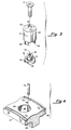
- fastener assembly 10 includes the cylindrical support structure 12, a bushing 16 and a nut 14.
- the screw 6 is mated with the bushing 16 and the nut 14 to provide the interconnection 3.
- the forward missile shell 2 and the aft missile shell 4 are fabricated from titanium, as well as the cylindrical support structure 12.
- the bushing 16 fabricated from stainless steel, includes a cylindrical shaped structure with a bore (not numbered) provided through the center of the structure.
- the bore includes a first portion 26 having a first diameter to accommodate the shaft of the screw 6 and a second portion 27 having a second different diameter to accommodate the nut 14.
- a first end 32 of the bushing 16 is disposed against an inner surface 33 of the aft missile shell 4.
- the first end 32 of the bushing 16 includes a radially curved surface with a contour to match the shape of the contour of the inner surface 33 of the aft missile shell 4. The latter provides uniform compression between the first end 32 of the bushing 16 and the inner surface 33 of the aft missile shell 4 when the screw 6 is tightened with the nut 14.
- a second opposing end includes a pair of tangs, comprising tang 28 and tang 30, extending from the second opposing end.
- a slot 24 is provided within the outer surface as shown.
- the nut 14, here fabricated from stainless steel, includes an outer surface 41 with a diameter such that the nut 14 will fit into the second portion 27 of the bore within the bushing 16.
- a pair of lugs, comprising lug 38 and lug 40, extend from the outer surface 41 of nut 14, as shown, and engage tang 28 and tang 30 of the bushing 16 when the nut 14 is disposed within the bushing 16.
- the engagement provides torsional coupling between the tangs 28 and 30 of the bushing 16 and the lugs 38 and 40 of the nut 14.
- a radial face surface 36 of the nut 14 rests adjacent a radial face surface 34 of the bushing 16 when the nut 14 is mated with the bushing 16. Threads 43 are provided within the nut 14 to mate with mating threads 15 of the screw 6.
- the cylindrical support structure 12 here having a shape as shown, includes a plurality of bores, including a bore 44 and here numbering eleven, spaced circumferentially about the cylindrical support structure 12.
- the bore 44 is sized to accommodate the bushing 16 and the nut 14 such that the bushing 16 is constrained to a slip fit within the bore 44.
- the bore 44 is limited in depth and does not breach the inner sealed missile compartment 11 (FIG. 1).
- the bore 44 includes a wall surface 45 with a slot 42 provided therein. With the bushing 16 mounted within the bore 44 of the cylindrical support structure 12, the slot 24 of the bushing 16 is disposed adjacent the slot 42 within the bore 44 of the cylindrical support structure 12 and a pin 8 is disposed between the slots 24 and 42.
- each one of the plurality of bores spaced circumferentially about the cylindrical support structure 12 is similar to the bore 44 with each bore accommodating a corresponding bushing similar to the bushing 16, a corresponding nut similar to the nut 14 and a corresponding pin similar to the pin 8.
- a seal gland On either side of the plurality of bores, including bore 44, a seal gland, here seal gland 46 and seal gland 48 respectively, is provided circumferentially about the cylindrical support structure 12.
- Disposed within the seal glands 46 and 48 are a seal 20 and a seal 22, respectively.
- Each of the seals 20 and 22 is a methyl-phenol-silicone O-ring and provides a proper seal over a varying temperature range.
- the seal 20 provides a proper seal between the cylindrical support structure 12 and the forward missile shell 2.
- the seal 22 provides a proper seal between the cylindrical support structure 12 and the aft missile shell 4.
- the amount of thermal expansion for the cylindrical support structure 12 is different than the amount of thermal expansion of the forward missile shell 2 and the aft missile shell 4, since the cylindrical support structure 12 is exposed to less heat than the forward missile shell 2 and the aft missile shell 4. Since forward missile shell 2 and aft missile shell 4 are independent of the cylindrical support structure 12, unrestrained thermal growth of the forward missile shell 2 and the aft missile shell 4 can occur independent of the cylindrical support structure 12, thus reducing missile shell distortion.
Landscapes
- Engineering & Computer Science (AREA)
- General Engineering & Computer Science (AREA)
- Mechanical Engineering (AREA)
- Chemical & Material Sciences (AREA)
- Aviation & Aerospace Engineering (AREA)
- Combustion & Propulsion (AREA)
- Connection Of Plates (AREA)
- Clamps And Clips (AREA)
- Gasket Seals (AREA)
Claims (11)
- Befestigungsanordnung, enthaltend:ein zylindrisches Tragteil (12) mit einer Bohrung (44);eine innerhalb der Bohrung (44) des zylindrischen Tragteiles (12) angeordnete Buchse (16), die so ausgebildet ist, daß sie in der Bohrung (44) des zylindrischen Tragteiles (12) nach einwärts und auswärts gleiten kann;Mittel (8, 24, 42) zum Verhindern einer Drehung der Buchse (16) innerhalb der Bohrung (44) des zylindrischen Tragteils (12); undeine Mutter (14), die teilweise innerhalb der Buchse (16) angeordnet ist und mit dieser Buchse (16) drehfest gekoppelt ist.
- Befestigungsanordnung nach Anspruch 1, dadurch gekennzeichnet, daß die Bohrung (44) in dem zylindrischen Tragteil (12) teilweise untergebracht ist und eine Wandfläche (45) mit einem Schlitz (42) aufweist; daß die Buchse (16) eine Außenfläche mit einem darin vorgesehenen Schlitz (24), eine Bohrung mit einem ersten Abschnitt (26), der einen ersten Durchmesser aufweist, und einem zweiten Abschnitt (27), der einen zweiten, unterschiedlichen Durchmesser aufweist, und ein Paar von Zungen (28, 30) hat, die von einem Ende der Buchse wegragen, daß die Mutter (14) teilweise in dem zweiten Abschnitt (27) der Bohrung der Buchse (16) untergebracht ist und eine Außenfläche mit einem Paar von Ansätzen (38, 40) daran aufweist, welche mit dem Paar von Zungen (28, 30) der Buchse (16) in Eingriff stehen; und daß die Mittel zum Verhindern eines Drehens der Buchse (16) einen Stift (18) enthalten, der so angeordnet ist, daß er in den Schlitz (42) der Wandfläche (45) des zylindrischen Tragteiles (12) und den Schlitz (24) der Buchse (16) eingreift.
- Befestigungsanordnung nach Anspruch 2, dadurch gekennzeichnet, daß das gegenüberliegende Ende der Buchse (16) eine radial gekrümmte Fläche (32) solchen Umrisses aufweist, daß sie an die Innenfläche eines Raketengehäuses (4) angepaßt ist, wenn das Raketengehäuse (4) an dem gegenüberliegenden Ende der Buchse (16) anliegt.
- Befestigungsanordnung nach Anspruch 1 oder 3, dadurch gekennzeichnet, daß das zylindrische Tragteil (12) weiter einen ersten Dichtungsflansch (46), der vor der Bohrung (44) des zylindrischen Tragteiles (12) gelegen ist, und einen zweiten Dichtungsflansch (48) aufweist, der hinter der Bohrung (44) des zylindrischen Tragteiles (12) gelegen ist, und daß ein erster O-Ring (20) an dem ersten Dichtungsflansch (46) vorgesehen ist und ein zweiter O-Ring (22) an dem zweiten Dichtungsflansch (48) vorgesehen ist.
- Befestigungsanordnung nach Anspruch 4, dadurch gekennzeichnet, daß das zylindrische Tragteil (12) aus Titan gefertigt ist und daß die Buchse (16) und die Mutter (14) aus rostfreiem Stahl gefertigt sind.
- Befestigungsanordnung nach Anspruch 5, dadurch gekennzeichnet, daß der erste und der zweite O-Ring (20, 22) aus Methyl-Phenol-Silicon gefertigt sind.
- Befestigungsanordnung nach Anspruch 2, gekennzeichnet durch:(a) eine Mehrzahl von Buchsen (16), wobei jede Buchse ein erstes Ende und ein zweites Ende sowie eine Innenfläche und eine Außenfläche aufweist und die Innenfläche einen ersten Abschnitt (26) mit einem ersten Durchmesser und einen zweiten Abschnitt (27) mit einem zweiten, unterschiedlichen Durchmesser hat und die Außenfläche mit einem Schlitz (24) darin versehen ist, und jede Buchse (16) weiter ein Paar von Zungen (28, 30) besitzt, die von einem Ende wegstehen;(b) eine Mehrzahl von Muttern (14), von denen jede eine Innenfläche und eine Außenfläche hat, wobei die Innenfläche mit Gewinde (43) versehen und die Außenfläche so dimensioniert ist, daß sie innerhalb des zweiten Abschnittes (27) der Innenfläche einer entsprechenden Buchse (16) Aufnahme findet und wobei jede Mutter (14) weiter ein Paar von Vorsprüngen (38, 40) enthält, die an der Außenfläche angeordnet sind und mit dem Paar von Zungen (28, 30) der entsprechenden Buchse (16) in Eingriff stehen, wenn die Mutter (14) in die Buchse (16) eingesetzt ist;(c) die Ausbildung des zylindrischen Tragteiles mit einer Mehrzahl von Bohrungen (44), wobei jede Bohrung (44) das Tragteil teilweise durchdringt und eine Wandfläche (45) mit einem Schlitz (42) hat und so dimensioniert ist, daß eine entsprechende Mutter (14) und eine Buchse (16) darin Platz findet; und(d) eine Mehrzahl von Stiften (8), wobei jeder Stift (8) in Eingriff mit dem Schlitz (42) der Wandfläche (45) einer entsprechenden Bohrung (44) des zylindrischen Tragteils (12) und dem Schlitz (24) der Außenfläche einer entsprechenden Buchse (16) steht.
- Befestigungsanordnung nach Anspruch 7, dadurch gekennzeichnet, daß jede der Mehrzahl von Buchsen (16) weiter ein gegenüberliegendes Ende aufweist, das eine radial gekrümmte Oberfläche (32) solchen Umrisses aufweist, daß sie einer Innenfläche eines Raketengehäuses (4) angepaßt ist, wenn das Raketengehäuse (4) an das gegenüberliegende Ende jeder der Buchsen (16) angelegt ist.
- Befestigungsanordnung nach Anspruch 8, dadurch gekennzeichnet, daß das zylindrische Tragteil (2) weiter einen ersten Dichtungsflansch (46), der vor der Mehrzahl von Bohrungen (44) des zylindrischen Tragteiles (12) gelegen ist, und einen zweiten Dichtungsflansch (48) enthält, der hinter der Mehrzahl von Bohrungen (44) des zylindrischen Tragteils (12) gelegen ist, und daß ein erster O-Ring (20) an dem ersten Dichtungsflansch (46) und ein zweiter O-Ring (22) an dem zweiten Dichtungsflansch (48) angeordnet ist.
- Befestigungsanordnung nach Anspruch 9, dadurch gekennzeichnet, daß das zylindrische Tragteil (12) aus Titan gefertigt ist, und daß die Buchsen (16) und die Muttern (14) aus rostfreiem Stahl gefertigt sind.
- Befestigungsanordnung nach Anspruch 10, dadurch gekennzeichnet, daß der erste und der zweite O-Ring (20, 22) aus Methyl-Phenol-Silicon gefertigt sind.
Applications Claiming Priority (2)
| Application Number | Priority Date | Filing Date | Title |
|---|---|---|---|
| US810755 | 1991-12-18 | ||
| US07/810,755 US5314144A (en) | 1991-12-18 | 1991-12-18 | Thermally compensating insert fastener |
Publications (2)
| Publication Number | Publication Date |
|---|---|
| EP0547823A1 EP0547823A1 (de) | 1993-06-23 |
| EP0547823B1 true EP0547823B1 (de) | 1996-08-07 |
Family
ID=25204623
Family Applications (1)
| Application Number | Title | Priority Date | Filing Date |
|---|---|---|---|
| EP92311148A Expired - Lifetime EP0547823B1 (de) | 1991-12-18 | 1992-12-07 | Zusammenbauelement zum Ausgleich von temperaturbedingten Verformungen |
Country Status (4)
| Country | Link |
|---|---|
| US (1) | US5314144A (de) |
| EP (1) | EP0547823B1 (de) |
| JP (1) | JP3229669B2 (de) |
| DE (1) | DE69212637T2 (de) |
Families Citing this family (24)
| Publication number | Priority date | Publication date | Assignee | Title |
|---|---|---|---|---|
| FR2703323B1 (fr) * | 1993-04-01 | 1995-06-30 | Europ Propulsion | Dispositif de protection thermique, notamment pour engin aerospatial. |
| FR2718706B1 (fr) * | 1994-04-15 | 1996-06-14 | Aerospatiale | Structure anti-étincelage, notamment pour aéronef. |
| US5876023A (en) * | 1996-09-18 | 1999-03-02 | Lord Corporation | Vibration isolation insert for aircraft floor planels and the like |
| ES2131476B1 (es) * | 1997-09-26 | 2000-03-01 | Const Aeronauticas Sa | Sistema de fijacion y separacion de satelites. |
| GB0117805D0 (en) * | 2001-07-21 | 2001-09-12 | Bae Systems Plc | A method of securing composite elements together |
| US6920802B2 (en) * | 2002-04-24 | 2005-07-26 | Saudi Arabian Oil Company | Adsorption trap for the detection of surface-active agents in gas streams |
| DE102004032554B4 (de) * | 2004-07-06 | 2006-07-13 | Airbus Deutschland Gmbh | Verschluss zum Verschließen einer Bauteilöffnung in einem Bauteil |
| US7422178B2 (en) * | 2004-10-21 | 2008-09-09 | Lockheed Martin Corporation | Non-threaded structural insert for component attachment |
| US7681834B2 (en) * | 2006-03-31 | 2010-03-23 | Raytheon Company | Composite missile nose cone |
| DE102009038644B4 (de) * | 2009-08-24 | 2015-01-08 | Airbus Operations Gmbh | Dekompressionselementbefestigungssystem für ein Flugzeug |
| JP5619446B2 (ja) * | 2010-03-23 | 2014-11-05 | 三菱重工業株式会社 | キャップ、これを用いた締結構造およびこの締結構造を有する航空機 |
| DE102010026839A1 (de) * | 2010-07-12 | 2012-01-12 | Airbus Operations Gmbh | Aerodynamische Verkleidungsvorrichtung, Flugzeug-Bauteilanordnung mit einer aerodynamischen Verkleidungsvorrichtung sowie Verfahren zur Montage eines solchen Verkleidungsteils |
| US8573911B2 (en) | 2011-09-28 | 2013-11-05 | Apple Inc. | Floating fasteners |
| US9719547B2 (en) * | 2013-03-21 | 2017-08-01 | The Boeing Company | Anti-rotation rivetless nut plate |
| EP2811176A1 (de) * | 2013-06-03 | 2014-12-10 | High Performance Space Structure Systems GmbH | Insert |
| FR3006723B1 (fr) * | 2013-06-11 | 2015-12-04 | Snecma | Dispositif de fixation de deux pieces entre elles |
| US9676469B2 (en) * | 2014-04-10 | 2017-06-13 | Lockheed Martin Corporation | System and method for fastening structures |
| US9711845B2 (en) * | 2014-07-21 | 2017-07-18 | The Boeing Company | Aerial vehicle radome assembly and methods for assembling the same |
| ES2575052B1 (es) * | 2014-12-23 | 2017-04-06 | Illinois Tools Works Inc. | Tuerca de compensación |
| JP6465482B2 (ja) * | 2015-02-19 | 2019-02-06 | 三菱航空機株式会社 | 貫通型フローティングナット |
| US10329008B2 (en) | 2016-06-24 | 2019-06-25 | The Boeing Company | Fluid-tight mechanical fastening system and associated structural assembly |
| FR3089202B1 (fr) | 2018-11-30 | 2022-05-27 | Airbus Operations Sas | Pièce de liaison apte à être liée à un élément de support d’un aéronef |
| EP3718878B1 (de) * | 2019-04-02 | 2024-02-21 | The Boeing Company | Mechanisches befestigungssystem und zugehörige strukturanordnung und verfahren |
| US11643208B2 (en) * | 2020-02-13 | 2023-05-09 | The Boeing Company | Adjustable coupling mechanisms for projectile devices |
Family Cites Families (11)
| Publication number | Priority date | Publication date | Assignee | Title |
|---|---|---|---|---|
| US782482A (en) * | 1904-06-02 | 1905-02-14 | David E Brockett | Pipe-coupling. |
| US2405643A (en) * | 1944-02-07 | 1946-08-13 | Lockheed Aircraft Corp | Structural connector |
| US2857950A (en) * | 1956-10-01 | 1958-10-28 | Avro Aircraft Ltd | Removable blind fastener with pivoted securing legs |
| US3122383A (en) * | 1959-02-17 | 1964-02-25 | Hirsch Joseph | Joint structure for cylindrical members |
| US3183024A (en) * | 1962-03-13 | 1965-05-11 | Jack A Myers | Radial wedge joint |
| US3253842A (en) * | 1963-12-10 | 1966-05-31 | Thiokol Chemical Corp | Shear key joint |
| US3434262A (en) * | 1967-09-08 | 1969-03-25 | Nat Screw & Mfg Co The | Blind fastener for sandwich panel and method |
| US3710673A (en) * | 1971-08-23 | 1973-01-16 | Gen Motors Corp | Fasteners |
| DE2617554C3 (de) * | 1976-04-22 | 1980-07-10 | Celler Maschinenfabrik Gebrueder Schaefer, 3100 Celle | Verbindung für Blechrohre, insbesondere für den Brunnenbau und für Pfahlgründungen |
| US4964594A (en) * | 1988-04-11 | 1990-10-23 | Texstar, Inc. | Blind fastener having special utility in the installation of transparencies in aircraft and the like |
| US5014934A (en) * | 1989-06-30 | 1991-05-14 | The Boeing Company | Removable seal for discontinuities in aircraft skin |
-
1991
- 1991-12-18 US US07/810,755 patent/US5314144A/en not_active Expired - Lifetime
-
1992
- 1992-10-19 JP JP28004192A patent/JP3229669B2/ja not_active Expired - Lifetime
- 1992-12-07 EP EP92311148A patent/EP0547823B1/de not_active Expired - Lifetime
- 1992-12-07 DE DE69212637T patent/DE69212637T2/de not_active Expired - Lifetime
Also Published As
| Publication number | Publication date |
|---|---|
| US5314144A (en) | 1994-05-24 |
| DE69212637T2 (de) | 1997-02-20 |
| DE69212637D1 (de) | 1996-09-12 |
| JPH05215108A (ja) | 1993-08-24 |
| JP3229669B2 (ja) | 2001-11-19 |
| EP0547823A1 (de) | 1993-06-23 |
Similar Documents
| Publication | Publication Date | Title |
|---|---|---|
| US5314144A (en) | Thermally compensating insert fastener | |
| US6358001B1 (en) | Turbine frame assembly | |
| US6439841B1 (en) | Turbine frame assembly | |
| US4268185A (en) | Mounting attachment | |
| US5737913A (en) | Self-aligning quick release engine case assembly | |
| US11572889B2 (en) | Blade pivot of adjustable orientation and of reduced bulk for a turbomachine fan hub | |
| US6116658A (en) | Counter torque tube connection | |
| US4840026A (en) | Band clamp apparatus | |
| US11933230B2 (en) | Modularity of an aircraft turbomachine | |
| US3427047A (en) | Tubular coupling having frangible connecting means | |
| GB2026650A (en) | Mounting Parts on Shafts | |
| CA2053036A1 (en) | Apparatus and method for supporting a vane segment in a gas turbine | |
| US5073039A (en) | Bearing assembly with thermal compensation | |
| US6817299B1 (en) | Fragmenting projectile having threaded multi-wall casing | |
| US2945704A (en) | Nose section-quick disconnect | |
| US3204515A (en) | Explosively releasable nut assembly | |
| EP0537946B1 (de) | Verbindungsanordnungen für getrennte Sektionen | |
| US4279530A (en) | Flanged connection for shafts or tubes | |
| US5074697A (en) | Releasable connector for interconnecting two parts subjected to high stresses | |
| RU2225664C2 (ru) | Обтекатель | |
| US3183024A (en) | Radial wedge joint | |
| EP0544678B1 (de) | Thermoaktivierbare kupplung | |
| GB2142125A (en) | Mounting push-in tubes in gun barrels | |
| WO1991011675A2 (en) | Cartridge case for a cased telescoped ammunition round | |
| US4274755A (en) | Rigid coupling, especially for turbogenerators |
Legal Events
| Date | Code | Title | Description |
|---|---|---|---|
| PUAI | Public reference made under article 153(3) epc to a published international application that has entered the european phase |
Free format text: ORIGINAL CODE: 0009012 |
|
| AK | Designated contracting states |
Kind code of ref document: A1 Designated state(s): BE DE FR GB IT |
|
| 17P | Request for examination filed |
Effective date: 19931216 |
|
| 17Q | First examination report despatched |
Effective date: 19941104 |
|
| GRAH | Despatch of communication of intention to grant a patent |
Free format text: ORIGINAL CODE: EPIDOS IGRA |
|
| GRAH | Despatch of communication of intention to grant a patent |
Free format text: ORIGINAL CODE: EPIDOS IGRA |
|
| GRAA | (expected) grant |
Free format text: ORIGINAL CODE: 0009210 |
|
| AK | Designated contracting states |
Kind code of ref document: B1 Designated state(s): BE DE FR GB IT |
|
| REF | Corresponds to: |
Ref document number: 69212637 Country of ref document: DE Date of ref document: 19960912 |
|
| ITF | It: translation for a ep patent filed | ||
| ET | Fr: translation filed | ||
| PLBE | No opposition filed within time limit |
Free format text: ORIGINAL CODE: 0009261 |
|
| 26N | No opposition filed | ||
| REG | Reference to a national code |
Ref country code: GB Ref legal event code: IF02 |
|
| PGFP | Annual fee paid to national office [announced via postgrant information from national office to epo] |
Ref country code: GB Payment date: 20101201 Year of fee payment: 19 |
|
| PGFP | Annual fee paid to national office [announced via postgrant information from national office to epo] |
Ref country code: DE Payment date: 20101130 Year of fee payment: 19 |
|
| PGFP | Annual fee paid to national office [announced via postgrant information from national office to epo] |
Ref country code: FR Payment date: 20111219 Year of fee payment: 20 |
|
| PGFP | Annual fee paid to national office [announced via postgrant information from national office to epo] |
Ref country code: BE Payment date: 20111229 Year of fee payment: 20 |
|
| PG25 | Lapsed in a contracting state [announced via postgrant information from national office to epo] |
Ref country code: IT Free format text: LAPSE BECAUSE OF NON-PAYMENT OF DUE FEES Effective date: 20111207 |
|
| REG | Reference to a national code |
Ref country code: DE Ref legal event code: R071 Ref document number: 69212637 Country of ref document: DE |
|
| REG | Reference to a national code |
Ref country code: DE Ref legal event code: R071 Ref document number: 69212637 Country of ref document: DE |
|
| REG | Reference to a national code |
Ref country code: GB Ref legal event code: PE20 Expiry date: 20121206 |
|
| BE20 | Be: patent expired |
Owner name: *RAYTHEON CY Effective date: 20121207 |
|
| PG25 | Lapsed in a contracting state [announced via postgrant information from national office to epo] |
Ref country code: GB Free format text: LAPSE BECAUSE OF EXPIRATION OF PROTECTION Effective date: 20121206 |
|
| PGFP | Annual fee paid to national office [announced via postgrant information from national office to epo] |
Ref country code: IT Payment date: 20111217 Year of fee payment: 20 |
|
| PGRI | Patent reinstated in contracting state [announced from national office to epo] |
Ref country code: IT Effective date: 20130510 |