EP0547841A2 - Kathodenstrahlröhrenanzeigegerät - Google Patents
Kathodenstrahlröhrenanzeigegerät Download PDFInfo
- Publication number
- EP0547841A2 EP0547841A2 EP92311307A EP92311307A EP0547841A2 EP 0547841 A2 EP0547841 A2 EP 0547841A2 EP 92311307 A EP92311307 A EP 92311307A EP 92311307 A EP92311307 A EP 92311307A EP 0547841 A2 EP0547841 A2 EP 0547841A2
- Authority
- EP
- European Patent Office
- Prior art keywords
- raster
- timebase
- frame
- line
- successive
- Prior art date
- Legal status (The legal status is an assumption and is not a legal conclusion. Google has not performed a legal analysis and makes no representation as to the accuracy of the status listed.)
- Ceased
Links
Images
Classifications
-
- H—ELECTRICITY
- H04—ELECTRIC COMMUNICATION TECHNIQUE
- H04N—PICTORIAL COMMUNICATION, e.g. TELEVISION
- H04N3/00—Scanning details of television systems; Combination thereof with generation of supply voltages
- H04N3/10—Scanning details of television systems; Combination thereof with generation of supply voltages by means not exclusively optical-mechanical
- H04N3/30—Scanning details of television systems; Combination thereof with generation of supply voltages by means not exclusively optical-mechanical otherwise than with constant velocity or otherwise than in pattern formed by unidirectional, straight, substantially horizontal or vertical lines
-
- G—PHYSICS
- G09—EDUCATION; CRYPTOGRAPHY; DISPLAY; ADVERTISING; SEALS
- G09G—ARRANGEMENTS OR CIRCUITS FOR CONTROL OF INDICATING DEVICES USING STATIC MEANS TO PRESENT VARIABLE INFORMATION
- G09G1/00—Control arrangements or circuits, of interest only in connection with cathode-ray tube indicators; General aspects or details, e.g. selection emphasis on particular characters, dashed line or dotted line generation; Preprocessing of data
- G09G1/04—Deflection circuits ; Constructional details not otherwise provided for
Definitions
- the present invention relates to cathode ray tube (CRT) display apparatus for displaying successive frames of a non-interlaced video image with improved character legibility.
- CTR cathode ray tube
- a CRT display such as a computer visual display unit or a television receiver for example, conventionally comprises a line timebase circuit for sequentially addressing one or more electron beams to successive pixels in a line from one side of a CRT to the other in response to a line timebase synchronisation signal, and a frame timebase circuit for sequentially addressing the or each electron beam to successive lines from the top of the CRT to the bottom in response to a frame timebase synchronisation signal.
- the or each electron beam follows a zig zag pattern over the area of the CRT screen.
- the zig zag pattern is usually, and will hereinafter be, referred to as a raster.
- cathode ray tube display apparatus comprising: a cathode ray tube display screen for displaying successive frames of a non-interlaced video image in response to excitation by at least one raster-scanned electron beam; a line timebase circuit for sequentially addressing the or each electron beam to successive pixels on the screen in a line of a raster in response to a line timebase sync signal; and a frame timebase circuit for sequentially addressing the or each electron beam to successive lines of the raster in response to a frame timebase sync signal; characterised in that the frame timebase circuit comprises means for offsetting successive frames of the video image in a direction transverse of the lines of the raster by a distance less than the spacing of adjacent lines of the raster.
- the present invention is based on the realisation that gaps between adjacent pixels on successive lines of the raster, that are produced by reducing the electron beam spot size to increase the inner contrast ratio of displayed characters, can be made invisible to the viewer by shifting successive frames of the video image in a direction transverse of the lines of the raster by a distance less than the spacing of adjacent lines of the raster. Because the persistence of a viewers eye effectively integrates the image content of successive frames, the relative movement of pixels between successive frames remains undetected. Thus, in appearance, a displayed character has smooth, unbroken strokes. Furthermore, because the successive frames have the same image content, there is no low frequency component in the image spectrum below the frame timebase frequency. Therefore, the displayed image is free from objectionable flicker.
- the present invention thus permits a small spot size to improve character legibility along successive lines of the raster without impairing character legibility between successive lines of the raster.
- the present invention extends to both colour and monochrome CRT displays. Indeed, when applied to a colour CRT display, the present invention advantageously tends to prevent generation of objectionable Moire fringe patterns screen because the spaces between adjacent lines of the raster in one frame are effectively filled in by the lines of the raster in the next frame.
- the offset means comprises a divide by two counter responsive to the line timebase sync signal for generating a square wave signal of half !the frequency of the line timebase sync signal in such a manner that successive frames of the raster correspond to alternate levels of the square wave signal.
- the counter permits successive frames of the video image to be identified without the need for complex electronic circuitry.
- the counter may be conveniently implemented by a widely available and inexpensive integrated circuit package.
- the frame timebase generator comprises a ramp signal generator for generating a ramp signal in response to the frame timebase sync signal
- the offset means comprises a summing amplifier for adding the square wave signal to the ramp signal to offset successive frames of the video image.
- successive frames of the video image may be offset by simple, and hence advantageous, addition of two electrical signals.
- the offset means may further comprise an analogue multiplexor for selecting any one of a plurality of amplitudes for the square signal in response to a digital control signal indicative of a desired one of a plurality of display modes of operation.
- the present invention may thus advantageously extend to CRT displays that are operable within a range of line refresh frequencies and a range of frame refresh frequencies as well as those that are operable only at fixed line and frame refresh frequencies.
- the frame timebase circuit is configured to respond to a frame sync signal of a frequency of at least 75Hz. Therefore, the pixel positions are modulated at a frequency of at least 37.5Hz.
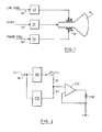
- a monochrome CRT display of the present invention comprises a monochrome cathode ray tube 10 having an electromagnetic coil assembly or yoke 20.
- a video amplifier 30 is connected to an electron gun (not shown) enclosed in the cathode ray tube 10.
- the yoke comprises line and frame deflection coils (not shown) respectively connected to a line timebase circuit 40 and a frame timebase circuit 50.
- the energy of an electron beam generated by the electron gun and directed towards the screen of the CRT is modulated by an input video signal 70.
- the line timebase circuit generates a sawtooth deflection current in the line deflection coils for sweeping the electron beam from one side of the screen to the other during a scan period and then rapidly returning the electron beam during a line retrace period.
- the frame timebase circuit simultaneously generates a sawtooth deflection current in the frame deflection coils for sweeping the electron beam from the top of the CRT screen to the bottom during a frame scan period and for rapidly returning the electron beam to the top of the screen during a frame retrace period.
- the outputs of the line and frame timebase circuits are respectively synchronised to the input video signal by input line and frame synchronisation (sync) signals, 60 and 80.
- the frame period is typically equivalent to hundreds of line scan periods to generate a high resolution video image.
- acceptable character legibility is achieved on a monochrome CRT screen when the brightness modulation index is 0.4 and on a colour CRT screen when the brightness modulation index is 0.7.
- acceptable character legibility is achieved on a CRT screen if the character inner contrast ratio is at least 3:1.
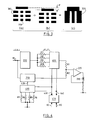
- the frame timebase stage 50 comprises a ramp signal generator 210 having an input connected to the frame sync signal 80 and an output connected, via resistor R2 to the input of a power amplifier 220.
- the output of the power amplifier 220 is connected to the frame deflection coils 230 of the yoke 20.
- the frame sync signal is also connected to the input of a divide by two counter200.
- the output of t he counter 200 is connected, via resistor R1 to to the input of the power amplifier 220.
- the ramp generator 210 generates a ramp signal at the same frequency as, and synchronised to the frame sync signal 80.
- the counter 200 responds to the frame sync signal by generating a square wave of half the frequency of the frame sync signal.
- the square wave is combined additively with the ramp signal atthe input of the power amplifier 220 according to the ratio of R1 to R2.
- R1, R2 and the power amplifier 220 in combination therefore act as a summing amplifier.
- successive frames of the video image displayed on the CRT screen correspond to the alternate high and low states of the square wave.
- the ration of the resistors R1 and R2 are selected in such a manner that the voltage difference between the high and low states of the square wave corresponds to an vertical offset between successive frames of the displayed video image of less than the spacing between adjacent lines of the raster.
- the square wave is added to the ramp signal before application of any S correction via an S correction network (not shown) so that the offset between successive frames is substantially equal from the top of the CRT screen to the bottom.
- Figure 3a shows an example of a character displayed in a frame corresponding to a high state in the square wave.
- the spot size is made small to optimise the inner character contrast ratio, there are gaps between adjacent pixels on successive lines of the raster.
- the brightness modulation index is therefore poor.
- Figure 3b shows the same character displayed in the next frame when the square wave has toggled to a low state. The character is shifted vertically by an amount equal to half the distance between successive lines of the raster.
- the frame sync signal is of sufficiently high frequency, the persistence of a viewers eye effectively integrates the image content of successive frames in such a manner that relative movement, of pixels between successive frames is not detected.
- the character has smooth, unbroken strokes.
- the frame sync signal has a frequency of 75Hz. Therefore, the pixel positions are modulated at a frequency of 37.5Hz. However, because successive frames have the same image content, there is no low frequency component in the image spectrum below 75Hz. Therefore, the displayed image is free from objectionable flicker.
- the present invention is equally applicable to a colour CRT display in which the video signal 70 comprises red, green and blue components for driving, respectively red, green and blue electron guns in the CRT 10.
- the present invention also extends to CRT displays capable of operating within a range of frame and line refresh frequencies.
- An example of such a display may be capable of operating in any one of four display modes with each display mode having different frame and line refresh requirements.
- the frame timebase circuit 50 comprises an analogue multiplexor 410 having a single line output connected to a reference input 420 of the ramp signal generator 210.
- the multiplexor 410 0 has a pair of binary control inputs, 430 and 440, connected to a mode control circuit 450 and four line inputs connected to a supply voltage via four resistors R3-R6.
- the mode control circuit is connected to the line sync signal 60 and the frame sync signal 80.
- Another analogue multiplexor 400 has a line output connected to the input of the power amplifier 220 via resistor R1.
- the multiplexor400 also has a pair of binary control inputs, 430 and 440, connected to the mode control circuit 450 and four line inputs connected to the output of the divide by two counter 200 via four resistors R7-R10.
- the mode control circuit 450 decodes the line and frame sync signals, 60 and 80 to determine the required display mode and sets the control inputs, 430 and 440, to one of four possible binary permutations, 01, 10, 11, and 00, accordingly.
- the control inputs, 430 and 440 determine, via the multiplexor 410, which one of the four resistors, R3-R6, connects the supply voltage V to the reference input of the ramp generator 210.
- Each value of the resistors, R3-R6, is selected to configure the ramp generator 210 to generate a ramp signal corresponding to a different one of the four display modes.
- control inputs, 430 and 440 determine, via multiplexor 400, which one of the four resistors, R7-R10, is connected in series with R1 between the output of the counter 220 and the input of the power amplifier 200.
- Each value of the resistors, R7 to R10 is selected to set, in accordance with a different one of the four display modes, the amplifier of the square wave added to the ramp signal at the in put of the porteram- plifier 220.
- a cathode ray tube display apparatus comprising: a cathode ray tube display screen (10) for displaying successive frames of a non-interlaced video image in response to excitation by at least one raster-scanned electron beam, a line timebase circuit (40) sequentially addresses the or each electron beam to successive pixels on the screen in a line of a raster in response to a line timebase sync signal, and a frame timebase (50) circuit sequentially addresses the or each electron team to successive lines of the raster in response to a frame timebase sync signal.
- the frame timebase circuit (50) comprises means for offsetting successive frames of the video image in a direction transverse of the lines of the raster by a distance less than the spacing of adjacent lines of the raster. Gaps between adjacent pixels on successive lines of the raster are thus made invisible to the viewer because the persistence of a viewers eye effectively integrates the image content of successive frames. Also, because the successive frames have the same image content, there is no low frequency component in the image spectrum below the frame timebase frequency. Therefore, the displayed image is advantageously free from objectionable flicker.
Landscapes
- Engineering & Computer Science (AREA)
- Radar, Positioning & Navigation (AREA)
- Remote Sensing (AREA)
- Physics & Mathematics (AREA)
- Computer Hardware Design (AREA)
- General Physics & Mathematics (AREA)
- Theoretical Computer Science (AREA)
- Multimedia (AREA)
- Signal Processing (AREA)
- Details Of Television Scanning (AREA)
- Controls And Circuits For Display Device (AREA)
Applications Claiming Priority (2)
| Application Number | Priority Date | Filing Date | Title |
|---|---|---|---|
| GB9126997 | 1991-12-19 | ||
| GB9126997A GB2262692A (en) | 1991-12-19 | 1991-12-19 | Crt display apparatus having increased character legibility |
Publications (2)
| Publication Number | Publication Date |
|---|---|
| EP0547841A2 true EP0547841A2 (de) | 1993-06-23 |
| EP0547841A3 EP0547841A3 (en) | 1996-12-11 |
Family
ID=10706546
Family Applications (1)
| Application Number | Title | Priority Date | Filing Date |
|---|---|---|---|
| EP92311307A Ceased EP0547841A3 (en) | 1991-12-19 | 1992-12-10 | Cathode ray tube display apparatus |
Country Status (4)
| Country | Link |
|---|---|
| US (1) | US5315310A (de) |
| EP (1) | EP0547841A3 (de) |
| JP (1) | JPH087539B2 (de) |
| GB (1) | GB2262692A (de) |
Cited By (1)
| Publication number | Priority date | Publication date | Assignee | Title |
|---|---|---|---|---|
| US7154532B2 (en) | 2003-02-07 | 2006-12-26 | Tektronix, Inc. | Video field rate persistence |
Families Citing this family (6)
| Publication number | Priority date | Publication date | Assignee | Title |
|---|---|---|---|---|
| US5602932A (en) * | 1994-03-04 | 1997-02-11 | International Business Machines Corporation | Photodetector array based image analysis apparatus |
| US5767632A (en) * | 1994-08-04 | 1998-06-16 | Hitachi, Ltd. | CRT display device |
| US6094018A (en) * | 1998-10-01 | 2000-07-25 | Sony Corporation | Method and apparatus for providing moire effect correction based on displayed image resolution |
| US6225762B1 (en) | 1998-10-01 | 2001-05-01 | Sony Corporation | Method and apparatus for providing moiré effect correction on a multi-scan display monitor |
| US9160283B2 (en) * | 2013-04-12 | 2015-10-13 | Rf Micro Devices, Inc. | Integrated pulse shaping biasing circuitry |
| US9520837B1 (en) * | 2016-03-09 | 2016-12-13 | Qorvo Us, Inc. | Pulse shaping biasing circuitry |
Family Cites Families (11)
| Publication number | Priority date | Publication date | Assignee | Title |
|---|---|---|---|---|
| US3422304A (en) * | 1967-09-15 | 1969-01-14 | Ibm | Logic controlled deflection system |
| US4215414A (en) * | 1978-03-07 | 1980-07-29 | Hughes Aircraft Company | Pseudogaussian video output processing for digital display |
| US4251835A (en) * | 1978-11-06 | 1981-02-17 | Tektronix, Inc. | Image-forming system for obscuring poster lines |
| NL7901119A (nl) * | 1979-02-13 | 1980-08-15 | Philips Nv | Beeldweergeefinrichting voor het als een tweevoudig geinterlinieerd televisiebeeld weergeven van een door een beeldsignaalgenerator opgewekt tweewaardig signaal. |
| US4322750A (en) * | 1979-05-08 | 1982-03-30 | British Broadcasting Corporation | Television display system |
| JPS5766477A (en) * | 1980-10-13 | 1982-04-22 | Tokyo Shibaura Electric Co | Video display unit |
| EP0053207B1 (de) * | 1980-11-28 | 1984-08-15 | International Business Machines Corporation | Einrichtung zur Verminderung des Flimmerns eines Kathodenstrahl-Anzeigesystems mit Rasterablenkung |
| US4520391A (en) * | 1982-12-20 | 1985-05-28 | International Business Machines Corporation | Diagonal grid image communication and display |
| DE3306879A1 (de) * | 1983-02-26 | 1984-08-30 | Licentia Patent-Verwaltungs-Gmbh, 6000 Frankfurt | Schaltung zur wiedergabe zweier halbbilder |
| US4697177A (en) * | 1984-12-26 | 1987-09-29 | High Resolution Television, Inc. | High resolution dot-matrix character display |
| JPS6249396A (ja) * | 1985-08-28 | 1987-03-04 | 加賀電子株式会社 | デイスプレイの疑似インタレス走査方法 |
-
1991
- 1991-12-19 GB GB9126997A patent/GB2262692A/en not_active Withdrawn
-
1992
- 1992-10-21 JP JP4282832A patent/JPH087539B2/ja not_active Expired - Lifetime
- 1992-12-04 US US07/985,772 patent/US5315310A/en not_active Expired - Fee Related
- 1992-12-10 EP EP92311307A patent/EP0547841A3/en not_active Ceased
Cited By (1)
| Publication number | Priority date | Publication date | Assignee | Title |
|---|---|---|---|---|
| US7154532B2 (en) | 2003-02-07 | 2006-12-26 | Tektronix, Inc. | Video field rate persistence |
Also Published As
| Publication number | Publication date |
|---|---|
| JPH05249910A (ja) | 1993-09-28 |
| GB9126997D0 (en) | 1992-02-19 |
| EP0547841A3 (en) | 1996-12-11 |
| US5315310A (en) | 1994-05-24 |
| JPH087539B2 (ja) | 1996-01-29 |
| GB2262692A (en) | 1993-06-23 |
Similar Documents
| Publication | Publication Date | Title |
|---|---|---|
| US5193006A (en) | Video display apparatus for pictures with different aspect ratios | |
| JP3295437B2 (ja) | 表示装置 | |
| US4760455A (en) | Picture output device | |
| GB2111343A (en) | Double-scanning non-interlace television receiver | |
| JP4340821B2 (ja) | 映像機器および映像表示方法 | |
| JP3301803B2 (ja) | テレビジョン受信機 | |
| US4709267A (en) | Synchronizing circuit with improved interlace arrangement | |
| US5315310A (en) | Cathode ray tube display apparatus | |
| US5381182A (en) | Flat panel image reconstruction interface for producing a non-interlaced video signal | |
| US5166791A (en) | Video picture and waveform display with line selection | |
| US4887010A (en) | Display device using shadowmask CRT | |
| KR100312146B1 (ko) | 텔레비젼수상기 | |
| EP0805602A2 (de) | Kathodenstrahlröhre | |
| US6094018A (en) | Method and apparatus for providing moire effect correction based on displayed image resolution | |
| US4456923A (en) | Color television display device comprising a plurality of picture display tubes | |
| KR19990037408A (ko) | 다중 주파수 스캐닝 모니터에 대해적합한 샤프니스증강을 제공하기 위한 장치 및 방법 | |
| CA2041109A1 (en) | Television apparatus | |
| JP3435790B2 (ja) | カラー陰極線管表示装置 | |
| EP0732680A2 (de) | Anzeigeeinrichtung mit Bandbreitenregelung für Video | |
| US6570625B1 (en) | Display apparatus and display method | |
| US5621276A (en) | Cathode ray tube | |
| JP3316282B2 (ja) | テレビジョン受像機 | |
| GB2181028A (en) | Hybrid display system | |
| KR20010029786A (ko) | 소직경의 빔 스포트를 공급할 수 있는 씨알티 시스템 | |
| Doyle et al. | The application and system aspects of the Zeus display |
Legal Events
| Date | Code | Title | Description |
|---|---|---|---|
| PUAI | Public reference made under article 153(3) epc to a published international application that has entered the european phase |
Free format text: ORIGINAL CODE: 0009012 |
|
| AK | Designated contracting states |
Kind code of ref document: A2 Designated state(s): DE FR GB |
|
| 17P | Request for examination filed |
Effective date: 19931021 |
|
| PUAL | Search report despatched |
Free format text: ORIGINAL CODE: 0009013 |
|
| AK | Designated contracting states |
Kind code of ref document: A3 Designated state(s): DE FR GB |
|
| 17Q | First examination report despatched |
Effective date: 19970507 |
|
| GRAG | Despatch of communication of intention to grant |
Free format text: ORIGINAL CODE: EPIDOS AGRA |
|
| 18R | Application refused |
Effective date: 19980418 |