EP0547895B1 - Méthode pour transmettre des informations de rectifiage à une commande numérique de rectifieuse pour verres de lunettes - Google Patents
Méthode pour transmettre des informations de rectifiage à une commande numérique de rectifieuse pour verres de lunettes Download PDFInfo
- Publication number
- EP0547895B1 EP0547895B1 EP92311521A EP92311521A EP0547895B1 EP 0547895 B1 EP0547895 B1 EP 0547895B1 EP 92311521 A EP92311521 A EP 92311521A EP 92311521 A EP92311521 A EP 92311521A EP 0547895 B1 EP0547895 B1 EP 0547895B1
- Authority
- EP
- European Patent Office
- Prior art keywords
- lenses
- lens
- demonstration
- edger
- computer
- Prior art date
- Legal status (The legal status is an assumption and is not a legal conclusion. Google has not performed a legal analysis and makes no representation as to the accuracy of the status listed.)
- Expired - Lifetime
Links
Images
Classifications
-
- G—PHYSICS
- G02—OPTICS
- G02C—SPECTACLES; SUNGLASSES OR GOGGLES INSOFAR AS THEY HAVE THE SAME FEATURES AS SPECTACLES; CONTACT LENSES
- G02C13/00—Assembling; Repairing; Cleaning
- G02C13/003—Measuring during assembly or fitting of spectacles
- G02C13/005—Measuring geometric parameters required to locate ophtalmic lenses in spectacles frames
-
- G—PHYSICS
- G02—OPTICS
- G02C—SPECTACLES; SUNGLASSES OR GOGGLES INSOFAR AS THEY HAVE THE SAME FEATURES AS SPECTACLES; CONTACT LENSES
- G02C13/00—Assembling; Repairing; Cleaning
- G02C13/003—Measuring during assembly or fitting of spectacles
-
- G—PHYSICS
- G05—CONTROLLING; REGULATING
- G05B—CONTROL OR REGULATING SYSTEMS IN GENERAL; FUNCTIONAL ELEMENTS OF SUCH SYSTEMS; MONITORING OR TESTING ARRANGEMENTS FOR SUCH SYSTEMS OR ELEMENTS
- G05B19/00—Program-control systems
- G05B19/02—Program-control systems electric
- G05B19/42—Recording and playback systems, i.e. in which the program is recorded from a cycle of operations, e.g. the cycle of operations being manually controlled, after which this record is played back on the same machine
- G05B19/4202—Recording and playback systems, i.e. in which the program is recorded from a cycle of operations, e.g. the cycle of operations being manually controlled, after which this record is played back on the same machine preparation of the program medium using a drawing, a model
- G05B19/4205—Recording and playback systems, i.e. in which the program is recorded from a cycle of operations, e.g. the cycle of operations being manually controlled, after which this record is played back on the same machine preparation of the program medium using a drawing, a model in which a drawing is traced or scanned and corresponding data recorded
-
- G—PHYSICS
- G05—CONTROLLING; REGULATING
- G05B—CONTROL OR REGULATING SYSTEMS IN GENERAL; FUNCTIONAL ELEMENTS OF SUCH SYSTEMS; MONITORING OR TESTING ARRANGEMENTS FOR SUCH SYSTEMS OR ELEMENTS
- G05B2219/00—Program-control systems
- G05B2219/30—Nc systems
- G05B2219/32—Operator till task planning
- G05B2219/32022—Ordering, remote ordering, enter article and operations needed, create jobfile
-
- G—PHYSICS
- G05—CONTROLLING; REGULATING
- G05B—CONTROL OR REGULATING SYSTEMS IN GENERAL; FUNCTIONAL ELEMENTS OF SUCH SYSTEMS; MONITORING OR TESTING ARRANGEMENTS FOR SUCH SYSTEMS OR ELEMENTS
- G05B2219/00—Program-control systems
- G05B2219/30—Nc systems
- G05B2219/45—Nc applications
- G05B2219/45175—Glasses, spectacles
Definitions
- Prescription ophthalmic lenses for eyesight corrective glasses must be edged to specific measurements and shapes to mount in eyeglass frames.
- the eye care doctor or other professional eye wear dispenser selects the frames and lenses for each patient's optical needs.
- Most eye care professionals stock frames at their location from which the patient makes his or her choice.
- the eye care professional then ships the frames to an optical laboratory so the lenses can be shaped to fit the frames.
- the present invention eliminates the need to ship eyeglass frames to a location where the lens edging will be performed, thus eliminating the cost of shipping the frames and the time delay factor in furnishing such frames to off-site optical laboratories.
- FR-A-2 602 880 discloses an arrangement by which frames are traced and the resulting data is transmitted to a remote production site.
- US-A-4 817 024 also discloses an arrangement in which the shape of a frame is traced and transmitted to a remote production site. A sheet having a horizontal and a vertical line is employed during the tracing process.
- the method of this disclosure requires no additional capital investment to the eyewear prescriber or dispenser. It will eliminate the need for future capital expenditures at their locations and can make obsolete many that are already in place. No technical skill beyond that which is normal and customary will be required at a professional eyewear dispenser's location.
- the ophthalmic lens pattern scale of this disclosure employs laser measurements with exact dimensions and will be provided as part of the system.
- the prescribing eyeglass doctor or eye glass dispenser is provided with an ophthalmic lens pattern scale that is described in the attached description of the preferred embodiment.
- the eye wear dispenser places eyeglass frames selected in an ophthalmoscope and marks the horizontal axis of the prescribed lens on the demonstration lenses provided by the frame manufacturer.
- the eye wear dispenser after removing the demonstration lenses from the frames, places the lenses on the ophthalmic lens pattern scale. He or she then aligns the identifying axis markings with the alignment markings on the pattern scale and traces the right and left demonstration lenses with a marking device furnished with the lens pattern scale.
- the lens pattern scale Upon completion of the tracing the lens pattern scale is inserted into the digital data transmitter of this disclosure.
- This transmitter digitizes the shape and dimensions reflected on the lens pattern scale tracing and transmits this digital data via an existing data transmission carrier to an off-site laboratory or manufacturing location.
- a digital data receiver and processor is located at the receiving end and is activated by the electronic transmission signal.
- the data receiver automatically receives and stores the data until it is needed by an operator at the receiving location.
- the receiving operator at his or her discretion, activates the data receiver and withdraws the digital data from storage, calls for the unit to automatically adjust for any data transmission distortion anomalies and to reconstruct the digital data receiver's preliminary interpretation of the lens pattern scale transmission.
- the data receiver unit automatically, in response to an operator command, adjusts and corrects to exact scale any tracing errors or omissions made by the eye wear provider at the point of origin. After performing these functions the exact cloned shape and size of the demonstration lenses are now in the digital database. Additionally, the receiver is designed to notify the operator to reject any reconstructed image or shape that is apparently too far out of tolerance for the unit to automatically correct. The operator, in this instance, will then notify the eye wear provider to make a correction on the lens pattern scale and to then re-transmit.
- the operator after determining that all functions are completed and that the data is structured to define the exact cloned shape and size of the demonstration lenses, calls for the receiver to convert automatically this data to a specific data interface format that is then transferred and recorded on a standard computer floppy disk that then contains computerized directions for a numerically controlled edger system.
- Edger systems which are provided by others, are common at most ophthalmic laboratories for edging lenses to mount in the frames.
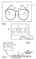
- Figure 1 illustrates eyeglass frames having demonstration lenses therein that have been selected by or for a user. It is an objective of the eye care provider to have lenses furnished by an optician with a prescribed refraction index ground therein to meet the ophthalmic needs of the patient and with edges to fit the frames.
- Figure 1 illustrates the frames having the demonstration lenses therein positioned on an ophthalmoscope by which the horizontal axis of the demonstration lenses are marked.
- Figure 2 shows the demonstration lenses having been removed from the frame and placed on a lenses pattern scale having a horizontal axis dashed line marked thereon.
- Figure 2 also shows a drawing pen. After the lenses are properly aligned with respect to the horizontal line they are traced onto the lens pattern scale with the drawing pen.
- Figure 3 shows a lens pattern scale as provided in Figure 2 with the outline of the required lenses traced thereon that is fed into a digital data transmitter that converts the information contained on the ophthalmic lens pattern scale into digitized data that is transmitted by a data carrier that can be such as a telephone line in the same way that a facsimile message is transmitted.
- a data carrier that can be such as a telephone line in the same way that a facsimile message is transmitted.
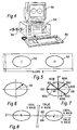
- Figure 4 illustrates a typical personal computer that is capable of receiving, storing and processing the digital data that contains information defining the outline of the demonstration lenses.
- Figures 5-11 are illustrative of processing steps that take place within the computer.
- Figure 5 illustrates that the computer finds a true coordinate system for the frame and the outline of the lenses.
- Figure 6 illustrates that the computer, by proper software programming, analyzes the image of one of the lenses and produces an optimum radius measurement for each of the lens.
- Figure 7 illustrates that the computer, by proper software programming, makes radial measurements taken at selected angles, in a clockwise or counterclockwise direction, of the lens outline.
- Figure 7 illustrates that the program within the computer provides for means to make tilt adjustment to to find the true coordinate system for the two lenses and to find the true centers based on the true coordinate system.
- Figure 9 shows a frame digitizer scanning to locate the center point of the lens.
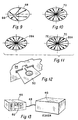
- Figure 10 illustrates that the computer program, after the correct center of a lens has been determined, determines the numerical data defining the outline of the lens.
- Figure 11 illustrates the program function wherein the digital signals have been generating defining the shape of both the right and left lenses and wherein the shapes can be compared to uncover possible error.
- Figure 12 shows that the program within the computer of Figure 4 provides the digital signal necessary for operation of an edger and places the digital signal on a floppy disc within the computer that may be withdrawn from the computer for use as required.
- Figure 13 illustrates the floppy disc having the digital information defining the outline of the left and right side lenses encoded therein being inserted into the file server of a numerically controlled edger system, the edger serving to shape and bevel the lenses so as to clone the demonstration lenses, after which the lenses can be delivered to the eye care provider for insertion into the frames so that they will be ready for use by the patient.
- Figure 1 shows the first step in which eyeglass frames, generally indicated by the numeral 10, have been selected by or for a patient.
- the eyeglass frames typically have a right demonstration lens 12 and a left demonstration lens 14 therein.
- the demonstration lenses 12, 14 typically do not have a refraction index ground therein but are provided by the manufacturer of eyeglass frame 10 to maintain the frames in proper shape during shipment and to better illustrate to the prospective user the appearance of the frames with glass therein. Further, demonstration lenses 12, 14, accurately define the shape of the lenses which must be inserted into frame 10 for proper use by the patient.
- Figure 1 shows the use of a ophthalmoscope 16 for marking the horizontal axis of the demonstration lenses before they are removed from the frame.
- the horizontal axis may be marked by the use of the ophthalmoscope by dots 18 marked on the demonstration lenses 12, 14. After marking dots 18 thereon the demonstration lenses are removed from frame 10.
- the eye care provider places demonstration lenses 12, 14 onto a lens pattern scale 20 that has a horizontal axis marked thereon, indicated by the dotted line 22.
- the eye care provider aligns demonstration lenses 12, 14 so that dots 18 fall on the horizontal axis dotted line 22 and then, using a marking instrument 24, marks the outline of demonstration lenses 12, 14 onto lens pattern scale 20.
- Figure 3 shows lens pattern scale 20 with the right demonstration lens outline 26 marked thereon and, in like manner, the outline 28 of left demonstration lens marked thereon.
- Lens pattern scale 20 is then fed into a digital data transmitter 30 as shown in Figure 3.
- the function of digital data transmitter 30 is to convert the information contained on the ophthalmic lens pattern scale 20 into digitized data that is then transmittable by any existing data transmission carrier 32, such as a telephone line.
- the digital data transmitter 30 is similar in function to a typical optical scanning digital data transmitter device or similar to a facsimile machine, in which the digital data representing the outline of the right and left demonstrator lenses 26, 28 is transmitted by carrier 32.
- the steps utilized in the equipment discussed to this point are located at the office of the eye care provider.
- the eye care provider need have only an ophthalmoscope 16 for determining the horizontal axis of the lenses, and data digital transmitter 30.
- the lens pattern scale is in the form of paper blanks.
- the ophthalmoscope which is an indispensable and universally utilized instrument already in the possession of the typical eye care provider. Therefore, the only ancillary piece of equipment needed by the eye care provider to practice the the system of this invention is digital data transmitter 30.
- a computer generally indicated by the numeral 34, that may be in the form of a typical personal computer having a display 36 and keyboard 38.
- the computer 34 has memory to receive the digital data transmitted by carrier 32 and to store the data until it is required.
- the data received from carrier 32 is processed within computer 34 to provide a digital signal necessary for operation of a numerically controlled edger, a commercially available piece of equipment as illustrated in Figure 13.
- the edger as shown in Figure 13 actually consists of two basic components, that is, an edger 40 that performs the physical task of shaping and bevelling a lens to the proper external circumferential configuration to replicate the demonstration lenses, and a control unit or file server 46.
- Edger 40 acts in conjunction with control unit 46 that provides the numerically control signals by conductor 48 to edger 40 in response to information provided from a floppy disc 50.
- the disc 50 is shown being inserted into the edger control unit 46.
- the function of computer 34 of Figure 4 is to provide on disc 50, as seen in Figure 12, the information necessary to operate edger control unit 46.
- the step of converting the signals received by computer 34 into signals to be placed on disc 50 for utilization by edger control unit 46 employs a computer program, the basic steps of which are graphically illustrated in Figures 5 - 11.
- Figure 5 shows that the program first determines the true coordinate system for the eyeglass lenses.
- the coordinate system determines the height and width measurement and defines horizontal and vertical scaling factors, which step can employ initial comparison of data with the typical eyeglass lens outlines 52 and 54.
- Figure 6 shows step 2, that is, the computer analyzes the image of each lens and produces an optimum radius measurement for each lens, the radius being indicated by the numeral 56.
- Figure 7 illustrates step 3 wherein first radial measurements are taken at zero degrees which is perpendicular to the true X axis 58 of each lens. Subsequent measurements, exemplified by radial measurements 60B - 60E, are taken in a clockwise or counterclockwise direction, the use of the counterclockwise direction being shown in Figure 7.
- Figure 8 shows the use of the program within computer 34 to make tilt adjustments to find the true coordinate system.
- the ideal horizontal coordinate is indicated by the numeral 62, and where the coordinate as detected by the data is illustrated by the numeral 64.
- the computer program must next provide a system for locating the center of both the right and left lenses. This system is illustrated in Figure 9 wherein a selected center 66 is tried and radial measurements made to the boundary 68 of the projected lens configuration. Upon analysis by the computer program the correct center 70 will be found.
- Figure 10 shows the program having located the correct lens center 70.
- axial measurements 72 as seen in Figure 11, can be made to determine the exact numerical data necessary to define the replicated outline of the right and left demonstration lenses indicated by the numerals 26A and 28A.
- the program within computer 34 has then generated digital data necessary for input into control unit 46 of edger 40 as shown in Figure 13.
- This digital data as derived by the computer program employing the sequence of steps, such as graphically illustrated in Figures 5 - 11, is then applied to floppy disc 50 within the computer. The disc 50 can be removed from the computer for subsequent use.
- disc 50 which may be the typical inexpensive floppy disc as commonly utilized on personal computers, is then placed into edger control unit 46 and the proper lenses are then manufactured by edger 40.
- the lenses having the correct refractory prescription already ground therein, are then properly edged to replicate the demonstration lenses and can then be delivered to the eye care provider.
- the eye care provider can then insert such lenses into frame 10 for delivery to the patient.
- the entire process of delivering the necessary data to the optician for replicating the demonstration lenses can be accomplished exceedingly expeditiously by the eye care provider with the requirement of only minimal technical skill.
- the optician requires only the use of a personal computer 34 in conjunction with a numerically controlled edger having a control unit 46 to then produce the required lenses, also with minimum technical skill requirements.
- the method of this invention can substantially reduce the time and expense of providing lenses for patients and therefore result in increased economy of providing eye care.
Landscapes
- Physics & Mathematics (AREA)
- General Physics & Mathematics (AREA)
- Health & Medical Sciences (AREA)
- Ophthalmology & Optometry (AREA)
- Optics & Photonics (AREA)
- Geometry (AREA)
- Engineering & Computer Science (AREA)
- Automation & Control Theory (AREA)
- Eyeglasses (AREA)
- Grinding And Polishing Of Tertiary Curved Surfaces And Surfaces With Complex Shapes (AREA)
Claims (5)
- Procédé par lequel un professionnel des soins optiques peut transmettre des informations pour une rectifieuse à un opticien se trouvant éloigné, procédé dans lequel le professionnel des soins optiques a une monture de lunettes choisie par ou pour un utilisateur, la monture de lunettes présentant des verres de démonstration y montés, l'opticien possédant une rectifieuse à commande numérique susceptible de façonner et de biseauter les verres en réponse à des signaux d'informations numériques, comprenant les étapes consistant à:(a) marquer un axe horizontal sur lesdits verres de démonstration tandis que lesdits verres de démonstration se trouvent dans ladite monture de lunettes,(b) enlever de ladite monture de lunettes chacun desdits verres de démonstration présentant ledit axe horizontal marqué,(c) placer lesdits verres de démonstration sur une plaque à modèle de verres présentant une ligne d'axe horizontal et aligner ledit axe horizontal marqué sur chacun des verres de démonstration sur la ligne d'axe horizontal de la plaque à modèle de verres,(d) tracer le contour de chacun desdits verres de démonstration sur ladite plaque à modèle de verres,(e) placer ladite plaque à modèle de verres présentant ledit contour des verres de démonstration y marqué dans un transmetteur de données numériques à balayage optique dans lequel les modèles des verres sont convertis en signaux d'informations numériques, les étapes (a) à (e) étant effectuées au lieu dudit professionnel des soins optiques,(f) transmettre lesdits signaux d'informations numériques par un transporteur de transmission de données à un ordinateur au lieu dudit opticien, les données étant reçues et mémorisées dans ledit ordinateur, et(g) traiter lesdits signaux d'informations numériques dans ledit ordinateur, pour fournir les signaux d'instruction de fonctionnement destinés à être utilisés dans ladite rectifieuse à commande numérique, pour faire façonner et biseauter des verres de lunettes par ladite rectifieuse, pour cloner lesdits verres de démonstration, les verres façonnés et biseautés étant alors prêts pour livraison audit professionnel des soins optiques, pour montage dans ladite monture de lunettes.
- Procédé suivant la revendication 1, dans lequel, à l'étape (g), lesdits signaux d'instruction de fonctionnement fournis par ladite étape de traitement des signaux d'informations numériques dans ledit ordinateur sont enregistrés sur une disquette d'ordinateur et la disquette est introduite dans un serveur de dossiers de ladite rectifieuse à commande numérique, pour faire façonner et biseauter des verres de lunettes par ladite rectifieuse à commande numérique, pour les rendre conformes auxdits verres de démonstration.
- Procédé suivant la revendication 1, dans lequel l'étape (g) de traitement desdits signaux d'informations numériques dans ledit ordinateur pour fournir les signaux d'instruction de fonctionnement destinés à être utilisés dans ladite rectifieuse à commande numérique comprend les étapes consistant à:(1) trouver un système de coordonnées pour établir l'axe horizontal des verres,(2) analyser des images de chaque verre et fournir le centre optimal pour chaque verre,(3) effectuer une série de mesures radiales à partir de ce centre optimal de chaque verre, dans le sens des aiguilles d'une montre ou dans le sens contraire à celles-ci, et(4) rendre numériques les données de l'étape (3), pour fournir un signal numérique définissant la limite de chaque verre en données conformes à un format de ladite rectifieuse à commande numérique.
- Procédé suivant la revendication 3, comprenant, entre les étapes (3) et (4), l'étape consistant à ajuster le système de coordonnées déterminé à l'étape (1), pour trouver le système de coordonnées réelles à l'aide des informations déterminées aux étapes (2) et (3).
- Procédé suivant la revendication 3, comprenant l'étape consistant à évaluer et à comparer les données de chaque verre avec celles de l'autre, pour créer un moyen pour détecter des erreurs dans lesdites données numériques définissant les limites de chaque verre.
Applications Claiming Priority (2)
| Application Number | Priority Date | Filing Date | Title |
|---|---|---|---|
| US809973 | 1991-12-18 | ||
| US07/809,973 US5257198A (en) | 1991-12-18 | 1991-12-18 | Method of transmitting edger information to a remote numerically controlled edger |
Publications (2)
| Publication Number | Publication Date |
|---|---|
| EP0547895A1 EP0547895A1 (fr) | 1993-06-23 |
| EP0547895B1 true EP0547895B1 (fr) | 1997-06-11 |
Family
ID=25202643
Family Applications (1)
| Application Number | Title | Priority Date | Filing Date |
|---|---|---|---|
| EP92311521A Expired - Lifetime EP0547895B1 (fr) | 1991-12-18 | 1992-12-17 | Méthode pour transmettre des informations de rectifiage à une commande numérique de rectifieuse pour verres de lunettes |
Country Status (4)
| Country | Link |
|---|---|
| US (1) | US5257198A (fr) |
| EP (1) | EP0547895B1 (fr) |
| CA (1) | CA2085630A1 (fr) |
| DE (2) | DE69220340T4 (fr) |
Families Citing this family (45)
| Publication number | Priority date | Publication date | Assignee | Title |
|---|---|---|---|---|
| DE4214326A1 (de) * | 1992-04-30 | 1993-11-04 | Wernicke & Co Gmbh | Vorrichtung zur randbearbeitung von brillenglaesern |
| US5967879A (en) * | 1994-04-26 | 1999-10-19 | Gottschald; Lutz | Process and system to machine and in particular to grind the optical surfaces and/or circumferential edge of eyeglass lenses |
| DE4427071A1 (de) * | 1994-08-01 | 1996-02-08 | Wernicke & Co Gmbh | Verfahren zur Ermittlung von Randungsdaten |
| US5648025A (en) * | 1995-12-13 | 1997-07-15 | Coburn Optical Industries, Inc. | Method for making light cured ophthalmic lens blocks |
| EP0946294B1 (fr) | 1996-11-07 | 2002-09-25 | Institut Français du Pétrole | Catalyseur comprenant au moins un element du groupe viib et son utilisation en hydrotraitement |
| JP3667483B2 (ja) * | 1997-02-10 | 2005-07-06 | 株式会社ニデック | レンズ研削加工装置 |
| ES2136541B1 (es) * | 1997-05-06 | 2000-08-01 | Indo Int Sa | Aparato para el centrado y bloqueo de un disco de lente oftalmica. |
| US5989462A (en) | 1997-07-31 | 1999-11-23 | Q2100, Inc. | Method and composition for producing ultraviolent blocking lenses |
| US6451226B1 (en) | 1998-09-25 | 2002-09-17 | Q2100, Inc. | Plastic lens compositions |
| JP3778707B2 (ja) * | 1998-09-29 | 2006-05-24 | 株式会社ニデック | 眼鏡レンズ加工装置 |
| US6419873B1 (en) | 1999-03-19 | 2002-07-16 | Q2100, Inc. | Plastic lens systems, compositions, and methods |
| FR2800172B1 (fr) * | 1999-10-20 | 2001-12-21 | Jacques Denis Exp | Procede de percage de verres optiques et systeme pour la mise en oeuvre d'un tel procede |
| US6381012B1 (en) | 2000-01-20 | 2002-04-30 | Virgil Thomas Yancy | System, method and article of manufacture to determine and communicate optical lens sizing and prescription information |
| US6960312B2 (en) * | 2000-03-30 | 2005-11-01 | Q2100, Inc. | Methods for the production of plastic lenses |
| US6944512B2 (en) | 2000-10-09 | 2005-09-13 | Seimens Aktiengesellschaft | Device and method for carrying out the decentralized production of desired products from different starting materials, and an automated process system |
| DE10049855A1 (de) * | 2000-10-09 | 2002-05-02 | Siemens Ag | Anordnung und Verfahren zur dezentralen Herstellung gewünschter Produkte aus unterschiedlichen Ausgangsstoffen und automatisiertes Prozesssystem |
| JP3990104B2 (ja) * | 2000-10-17 | 2007-10-10 | 株式会社ニデック | レンズ研削加工装置 |
| US7045081B2 (en) * | 2001-02-20 | 2006-05-16 | Q2100, Inc. | Method of monitoring components of a lens forming apparatus |
| US7060208B2 (en) * | 2001-02-20 | 2006-06-13 | Q2100, Inc. | Method of preparing an eyeglass lens with a controller |
| US7025910B2 (en) * | 2001-02-20 | 2006-04-11 | Q2100, Inc | Method of entering prescription information |
| US6893245B2 (en) * | 2001-02-20 | 2005-05-17 | Q2100, Inc. | Apparatus for preparing an eyeglass lens having a computer system controller |
| US7037449B2 (en) * | 2001-02-20 | 2006-05-02 | Q2100, Inc. | Method for automatically shutting down a lens forming apparatus |
| US7011773B2 (en) * | 2001-02-20 | 2006-03-14 | Q2100, Inc. | Graphical interface to display mold assembly position in a lens forming apparatus |
| US7051290B2 (en) | 2001-02-20 | 2006-05-23 | Q2100, Inc. | Graphical interface for receiving eyeglass prescription information |
| US7124995B2 (en) | 2001-02-20 | 2006-10-24 | Q2100, Inc. | Holder for mold assemblies and molds |
| US7074352B2 (en) * | 2001-02-20 | 2006-07-11 | Q2100, Inc. | Graphical interface for monitoring usage of components of a lens forming apparatus |
| US6962669B2 (en) * | 2001-02-20 | 2005-11-08 | Q2100, Inc. | Computerized controller for an eyeglass lens curing apparatus |
| US7139636B2 (en) | 2001-02-20 | 2006-11-21 | Q2100, Inc. | System for preparing eyeglass lenses with bar code reader |
| US7111372B2 (en) * | 2001-11-26 | 2006-09-26 | Opti-Clip Ltd. | Computer-controlled milling machine for producing lenses for clip-on accessory |
| US20060101629A1 (en) * | 2001-11-26 | 2006-05-18 | Opti-Clip International Llc | Computer-controlled milling machine for producing lenses for clip-on accessory |
| US7044429B1 (en) | 2002-03-15 | 2006-05-16 | Q2100, Inc. | Methods and systems for coating eyeglass lens molds |
| US20040230335A1 (en) * | 2003-05-13 | 2004-11-18 | Gerding David W. | System for capturing shape data for eyeglass lenses, and method for determining shape data for eyeglass lenses |
| DE10337153A1 (de) * | 2003-08-13 | 2005-03-10 | Alstom | Verfahren und Vorrichtung zum Wickeln einer Wicklung für einen Transformator oder eine Drosselspule |
| DE102004050483B4 (de) * | 2004-10-15 | 2008-05-08 | Weco Optik Gmbh | Verfahren und Vorrichtung zum Darstellen des dreidimensionalen Verlaufs einer geschlossen Kurve auf einem Bildschirm einer Brillenfassungsabtastvorrichtung oder einer Brillenglasrandbearbeitungsmaschine sowie Verwendung derartiger Vorrichtung für die Darstellung |
| US20060118501A1 (en) * | 2004-12-06 | 2006-06-08 | Opti-Clip International, Llc | Imaging of primary eyewear for remote production of secondary eyewear |
| JP5028024B2 (ja) * | 2006-05-02 | 2012-09-19 | 株式会社ニデック | ファセット加工領域設定装置 |
| US7392108B2 (en) * | 2006-08-29 | 2008-06-24 | National Optronics, Inc. | Method of controlling an edger device, machine programmed to edge an ophthalmic lens blank, and computer program |
| EP2111325A2 (fr) * | 2007-01-30 | 2009-10-28 | Zvi Feldman | Systèmes et procédés pour produire des pinces pour un article de lunetterie primaire |
| US9236024B2 (en) | 2011-12-06 | 2016-01-12 | Glasses.Com Inc. | Systems and methods for obtaining a pupillary distance measurement using a mobile computing device |
| US9483853B2 (en) | 2012-05-23 | 2016-11-01 | Glasses.Com Inc. | Systems and methods to display rendered images |
| US9311746B2 (en) | 2012-05-23 | 2016-04-12 | Glasses.Com Inc. | Systems and methods for generating a 3-D model of a virtual try-on product |
| US9286715B2 (en) | 2012-05-23 | 2016-03-15 | Glasses.Com Inc. | Systems and methods for adjusting a virtual try-on |
| US8967488B2 (en) * | 2013-05-17 | 2015-03-03 | Johnson & Johnson Vision Care, Inc. | Ophthalmic lens with communication system |
| EP2866074A1 (fr) * | 2013-10-25 | 2015-04-29 | ESSILOR INTERNATIONAL (Compagnie Générale d'Optique) | Procédé pour corriger un comportement de l'utilisateur afin de prévenir l'apparition ou de ralentir la progression d'un défaut visuel |
| CN117311263B (zh) * | 2023-11-29 | 2024-01-26 | 季华实验室 | 修边方向确定方法、装置、设备及存储介质 |
Family Cites Families (18)
| Publication number | Priority date | Publication date | Assignee | Title |
|---|---|---|---|---|
| US4423569A (en) * | 1981-10-02 | 1984-01-03 | Ait Industries, Inc. | Automatic lens edger |
| EP0092364A1 (fr) * | 1982-04-14 | 1983-10-26 | The Hanwell Optical Co. Limited | Méthode et appareil pour façonner un verre de lunettes pour l'emboîter dans une monture |
| DE3590087T1 (de) * | 1984-03-02 | 1986-06-05 | Hoya Corp., Tokio/Tokyo | Brillengestellform-Datenvorrichtung |
| US4656590A (en) * | 1984-11-07 | 1987-04-07 | Ronald Ace | Method and apparatus for making patterns for eyeglasses |
| US4781452A (en) * | 1984-11-07 | 1988-11-01 | Ace Ronald S | Modular optical manufacturing system |
| FR2582975B1 (fr) * | 1985-06-10 | 1987-08-28 | Briot Int | Appareil pour centrer et poser un adaptateur sur une ebauche de verre optique et pour commander une rectifieuse |
| US4912880A (en) * | 1985-12-06 | 1990-04-03 | Cobain Optical Industries, Inc. | Computerized tracing/edging system |
| US4711035A (en) * | 1986-08-04 | 1987-12-08 | Gerber Scientific Products, Inc. | Method and apparatus for making a pattern for a lens opening in an eyeglass frame |
| US4724617A (en) * | 1986-08-14 | 1988-02-16 | Gerber Scientific Products, Inc. | Apparatus for tracing the lens opening in an eyeglass frame |
| GB2194909B (en) * | 1986-08-14 | 1991-01-09 | Gerber Scient Products Inc | Optical lens pattern making system and method |
| US4945684A (en) * | 1987-01-12 | 1990-08-07 | Hoya Corporation | Method of and apparatus for processing peripheral edge of lens for spectacles |
| US4989316A (en) * | 1987-03-09 | 1991-02-05 | Gerber Scientific Products, Inc. | Method and apparatus for making prescription eyeglass lenses |
| GB8709127D0 (en) * | 1987-04-15 | 1987-05-20 | Autoflow Eng Ltd | Sensing lens blank |
| US4991305A (en) * | 1988-05-30 | 1991-02-12 | Hoya Corporation | Spectacle-lens-frame configuration measuring apparatus and article configuration measuring apparatus |
| FR2636555B1 (fr) * | 1988-09-22 | 1994-07-29 | Essilor Int | Restituteur de gabarit pour machine a meuler, en particulier pour verres de lunettes |
| US5053971A (en) * | 1989-08-30 | 1991-10-01 | Gerber Optical, Inc. | Method and apparatus for edging an optical lens |
| US5148637A (en) * | 1990-02-27 | 1992-09-22 | Bausch & Lomb Incorporated | Lens edging system with programmable feed and speed control |
| US4979311A (en) * | 1990-03-14 | 1990-12-25 | Bizer Jerry L | Instrument for determining the setting of a lens edger device to produce a properly sized lens |
-
1991
- 1991-12-18 US US07/809,973 patent/US5257198A/en not_active Expired - Lifetime
-
1992
- 1992-12-17 DE DE69220340T patent/DE69220340T4/de not_active Expired - Lifetime
- 1992-12-17 CA CA002085630A patent/CA2085630A1/fr not_active Abandoned
- 1992-12-17 EP EP92311521A patent/EP0547895B1/fr not_active Expired - Lifetime
- 1992-12-17 DE DE69220340A patent/DE69220340D1/de not_active Expired - Fee Related
Also Published As
| Publication number | Publication date |
|---|---|
| EP0547895A1 (fr) | 1993-06-23 |
| DE69220340T4 (de) | 1998-05-14 |
| CA2085630A1 (fr) | 1993-06-19 |
| DE69220340T2 (de) | 1998-01-08 |
| US5257198A (en) | 1993-10-26 |
| DE69220340D1 (de) | 1997-07-17 |
Similar Documents
| Publication | Publication Date | Title |
|---|---|---|
| EP0547895B1 (fr) | Méthode pour transmettre des informations de rectifiage à une commande numérique de rectifieuse pour verres de lunettes | |
| US4656590A (en) | Method and apparatus for making patterns for eyeglasses | |
| KR100515107B1 (ko) | 안경 가공방법 및 안경 프레임 | |
| EP1147853B1 (fr) | Production de verres de lunettes | |
| EP0092364A1 (fr) | Méthode et appareil pour façonner un verre de lunettes pour l'emboîter dans une monture | |
| CN103974803B (zh) | 眼镜镜片的镜片形状加工系统、眼镜镜片的制造方法及镜片形状加工机 | |
| JPS61284372A (ja) | 粗削りレンズの上にアダプタの中心合わせをして設置し、研磨機を操作するための装置と方法 | |
| US8295961B2 (en) | Spectacle lens supply system, ordering system, and manufacturing method | |
| US4817024A (en) | Spectacle-frame shape data producing method | |
| US6481095B1 (en) | Cup attaching apparatus | |
| EP2031434B1 (fr) | Procédé synchrone pour obtenir des fonctions de lunettes à commander | |
| US6381012B1 (en) | System, method and article of manufacture to determine and communicate optical lens sizing and prescription information | |
| US6599171B2 (en) | Cup attaching apparatus | |
| US7150528B2 (en) | Apparatus for positioning a semi-finished spectacle lens | |
| US5946074A (en) | Apparatus for centering a spectacles lens and positioning a gripping member thereon | |
| US12529909B2 (en) | Method of manufacturing an ophthalmic lens | |
| AU2010249222A1 (en) | Configuration of lenses | |
| US10339581B2 (en) | Dual-camera apparatus for deriving dimensional measurements and method of personalizing lens selection | |
| CA2196280A1 (fr) | Procede de determination de donnees concernant le bord d'un verre de lunettes | |
| JP2002303829A (ja) | 眼鏡レンズのマーキング方法及び装置 | |
| US20040230335A1 (en) | System for capturing shape data for eyeglass lenses, and method for determining shape data for eyeglass lenses | |
| EP4166275B1 (fr) | Procédé de détermination de la forme d'une bordure de monture de lunettes | |
| JPH06103369B2 (ja) | 眼鏡レンズの外径決定方法 | |
| CN104571138A (zh) | 从眼科对象获取和计算数据的方法和设备 | |
| HK1010578B (en) | Method of manufacturing spectacles |
Legal Events
| Date | Code | Title | Description |
|---|---|---|---|
| PUAI | Public reference made under article 153(3) epc to a published international application that has entered the european phase |
Free format text: ORIGINAL CODE: 0009012 |
|
| AK | Designated contracting states |
Kind code of ref document: A1 Designated state(s): DE FR GB IT |
|
| 17P | Request for examination filed |
Effective date: 19931215 |
|
| 17Q | First examination report despatched |
Effective date: 19950327 |
|
| GRAG | Despatch of communication of intention to grant |
Free format text: ORIGINAL CODE: EPIDOS AGRA |
|
| GRAH | Despatch of communication of intention to grant a patent |
Free format text: ORIGINAL CODE: EPIDOS IGRA |
|
| GRAH | Despatch of communication of intention to grant a patent |
Free format text: ORIGINAL CODE: EPIDOS IGRA |
|
| GRAA | (expected) grant |
Free format text: ORIGINAL CODE: 0009210 |
|
| AK | Designated contracting states |
Kind code of ref document: B1 Designated state(s): DE FR GB IT |
|
| REF | Corresponds to: |
Ref document number: 69220340 Country of ref document: DE Date of ref document: 19970717 |
|
| ET | Fr: translation filed | ||
| PLBE | No opposition filed within time limit |
Free format text: ORIGINAL CODE: 0009261 |
|
| STAA | Information on the status of an ep patent application or granted ep patent |
Free format text: STATUS: NO OPPOSITION FILED WITHIN TIME LIMIT |
|
| 26N | No opposition filed | ||
| PGFP | Annual fee paid to national office [announced via postgrant information from national office to epo] |
Ref country code: GB Payment date: 20001219 Year of fee payment: 9 |
|
| PGFP | Annual fee paid to national office [announced via postgrant information from national office to epo] |
Ref country code: FR Payment date: 20001227 Year of fee payment: 9 |
|
| PGFP | Annual fee paid to national office [announced via postgrant information from national office to epo] |
Ref country code: DE Payment date: 20010219 Year of fee payment: 9 |
|
| PG25 | Lapsed in a contracting state [announced via postgrant information from national office to epo] |
Ref country code: GB Free format text: LAPSE BECAUSE OF NON-PAYMENT OF DUE FEES Effective date: 20011217 |
|
| REG | Reference to a national code |
Ref country code: GB Ref legal event code: IF02 |
|
| PG25 | Lapsed in a contracting state [announced via postgrant information from national office to epo] |
Ref country code: DE Free format text: LAPSE BECAUSE OF NON-PAYMENT OF DUE FEES Effective date: 20020702 |
|
| GBPC | Gb: european patent ceased through non-payment of renewal fee |
Effective date: 20011217 |
|
| PG25 | Lapsed in a contracting state [announced via postgrant information from national office to epo] |
Ref country code: FR Free format text: LAPSE BECAUSE OF NON-PAYMENT OF DUE FEES Effective date: 20020830 |
|
| REG | Reference to a national code |
Ref country code: FR Ref legal event code: ST |
|
| PG25 | Lapsed in a contracting state [announced via postgrant information from national office to epo] |
Ref country code: IT Free format text: LAPSE BECAUSE OF NON-PAYMENT OF DUE FEES;WARNING: LAPSES OF ITALIAN PATENTS WITH EFFECTIVE DATE BEFORE 2007 MAY HAVE OCCURRED AT ANY TIME BEFORE 2007. THE CORRECT EFFECTIVE DATE MAY BE DIFFERENT FROM THE ONE RECORDED. Effective date: 20051217 |