EP0548009A1 - Vorschub- und Bremsvorrichtung an einem Flächenreinigungsgerät - Google Patents
Vorschub- und Bremsvorrichtung an einem Flächenreinigungsgerät Download PDFInfo
- Publication number
- EP0548009A1 EP0548009A1 EP92810948A EP92810948A EP0548009A1 EP 0548009 A1 EP0548009 A1 EP 0548009A1 EP 92810948 A EP92810948 A EP 92810948A EP 92810948 A EP92810948 A EP 92810948A EP 0548009 A1 EP0548009 A1 EP 0548009A1
- Authority
- EP
- European Patent Office
- Prior art keywords
- surface cleaning
- feed device
- cleaning device
- feed
- driven
- Prior art date
- Legal status (The legal status is an assumption and is not a legal conclusion. Google has not performed a legal analysis and makes no representation as to the accuracy of the status listed.)
- Granted
Links
Images

Classifications
-
- B—PERFORMING OPERATIONS; TRANSPORTING
- B62—LAND VEHICLES FOR TRAVELLING OTHERWISE THAN ON RAILS
- B62D—MOTOR VEHICLES; TRAILERS
- B62D51/00—Motor vehicles characterised by the driver not being seated
- B62D51/04—Motor vehicles characterised by the driver not being seated the driver walking
-
- E—FIXED CONSTRUCTIONS
- E01—CONSTRUCTION OF ROADS, RAILWAYS, OR BRIDGES
- E01C—CONSTRUCTION OF, OR SURFACES FOR, ROADS, SPORTS GROUNDS, OR THE LIKE; MACHINES OR AUXILIARY TOOLS FOR CONSTRUCTION OR REPAIR
- E01C23/00—Auxiliary devices or arrangements for constructing, repairing, reconditioning, or taking-up road or like surfaces
- E01C23/06—Devices or arrangements for working the finished surface; Devices for repairing or reconditioning the surface of damaged paving; Recycling in place or on the road
- E01C23/08—Devices or arrangements for working the finished surface; Devices for repairing or reconditioning the surface of damaged paving; Recycling in place or on the road for roughening or patterning; for removing the surface down to a predetermined depth high spots or material bonded to the surface, e.g. markings; for maintaining earth roads, clay courts or like surfaces by means of surface working tools, e.g. scarifiers, levelling blades
- E01C23/085—Devices or arrangements for working the finished surface; Devices for repairing or reconditioning the surface of damaged paving; Recycling in place or on the road for roughening or patterning; for removing the surface down to a predetermined depth high spots or material bonded to the surface, e.g. markings; for maintaining earth roads, clay courts or like surfaces by means of surface working tools, e.g. scarifiers, levelling blades using power-driven tools, e.g. vibratory tools
- E01C23/088—Rotary tools, e.g. milling drums
Definitions
- the present invention relates to a device for moving on a motor-driven surface cleaning device, which is equipped for manual feed with a land fixed to the surface cleaning device and has an axis arranged in the connection area of the land with two impellers, wherein the device for moving can be coupled to the surface cleaning device is.
- the applicant manufactures surface cleaning devices which have a motor-driven rotor drum which have a height adjustment in order to change the machining strength.
- the rotor drum is equipped with a large number of flakes.
- Surface cleaning devices of the type mentioned are manufactured in various sizes.
- the large and heavy surface cleaning devices are usually equipped with internal combustion engines, which not only drive the rotor drum, but also cause the device to advance.
- the lighter and smaller surface cleaning devices are mostly operated with electric or air motors.
- the rotor drum is driven by the motor.
- the feed is carried out by an operator who moves the device over the area to be worked.
- the surface cleaning device is provided with a landing and an axle arranged in the connection area of the landing with two impellers and a front roller.
- a reaction force acts on the surface cleaning device, so that the device tends to run away as a result of the direction of rotation of the milling cutter.
- the operator must therefore counteract this reaction force and either brake or push the device against the reaction force.
- the speed of movement of the surface cleaning device should be as constant as possible so that a uniform cleaning effect is achieved. This requires experience and, in the case of larger areas, a corresponding endurance.
- a corresponding couplable feed device for surface cleaning devices is known from CH-A-666'173.
- This known feed device can be coupled to the axis arranged in the connection area of the land and consists of a bicycle-like frame with two wheels and a pedal drive.
- This solution has proven itself for cleaning large areas, especially outdoors. However, this solution is too bulky and too little maneuverable for working on smaller surfaces, especially floors in closed rooms.
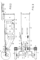
- FIG. 1 shows a side cleaning device 1 sold by the applicant on the market.
- a drive motor 2 can be seen, which drives a rotor drum accommodated in the housing via a transmission.
- the land 3 which has a handle 4 at the upper end, the surface cleaning device 1 is moved over the floor B to be cleaned.
- An axis 5 is arranged in the connection area of the land 3 to the surface cleaning device 1.
- the two running wheels 6 are mounted on this on both sides of the landing 3.
- the surface cleaning device is supported by at least one roller 7.
- the feed device 10 is detachably coupled at the bottom to the land 3, which runs obliquely upwards, and to the axis 5 of the surface cleaning device 1.
- the coupling of the feed device 10 to the axis 5 will be discussed later with reference to FIGS. 2 and 3.
- an eyelet 14 is attached to the device 10, in which a displaceable bolt 15 engages.
- the displaceable bolt 15 is mounted in a holder 18 which is arranged on the landing 3 in the upper region, near the handle 4.
- the feed device 10 has an enclosing protective housing 12 in which the drive is accommodated, which acts on at least one friction wheel 11. If the feed device 10 is coupled to the surface cleaning device 1, the friction wheel 11 presses on one of the two lateral impellers 6.
- the drive motor accommodated in the housing 12 of the feed device 10 can either be operated independently of an accumulator accommodated in the feed device or can be energetically coupled to the supply of the drive motor 2 of the surface cleaning device 1. In the example shown the latter variant applies. Therefore, one can see a connecting cable between the feed device 10 and the landing 3, which produces the electrical coupling 16.
- the common supply for the drive motor 2 for actuating the rotor drum in the surface cleaning device 1 and for the drive motor of the feed device 10 is not shown in the drawing.
- the supply of the motor in the feed device 10 by means of an accumulator is surely to be selected if the drive motor 2 for the rotor drum is an internal combustion engine.
- the rotor drum of the surface cleaning device 1 could also be operated as a drive 2 by means of an air motor. In this case, the device would be connected to a compressed air hose and an energetic coupling with the drive motor in the feed device 10 would again be possible.
- the handle 4 of the landing 3 shows an actuating lever 17 by means of which the relative distance of the feed device 10 to the axis 5 of the cleaning device 1, or the contact pressure of the friction wheel 11 on one of the impellers 6 of the cleaning device 1, can be changed.
- the corresponding mode of action will be discussed later.
- a schematically vertical longitudinal section through the feed device 10 is shown in simplified form in FIG. This corresponds approximately to a side view of the feed device with the omission of the closer side wall of the enveloping housing 12.
- a vertical partition 20 divides the housing into an accumulator chamber 21 and a drive chamber 22. If one works without a battery, the partition 20 can be dispensed with.
- a battery also not shown here
- the drive unit comprises an electric motor 24 which drives an output gear 27 via a converter 25 and a transmission gear 26.
- the driven wheel is connected to a drive wheel 29 via a transmission 28.
- the drive wheel 29 is fixed on a shaft 30, on each of which a secured friction wheel 11 is mounted on both sides. As previously described, the friction wheels 11 act on the impellers 6 of the surface cleaning device 1.
- the connection of the feed device 10 with the axis 5 of the surface cleaning device 1 is relatively complex.
- the entire feed device 10 is supported on the axis 5 by means of a two-pronged fork 31.
- a pivotable pulling hook 34 arranged centrally between the two prongs of the fork 31 is pivoted away. As soon as the two-pronged fork 31 is pressed down far enough on the axis 5, the hook 34 pivots back and engages around the axis 5.
- the pull hook 34 is pivotably arranged on a pull rod 35 which is guided through the fork 31 in a bearing sleeve 32.
- a pressure pin 34 'mounted laterally in the pull rod 35 is spring-loaded and presses on the pivotable pull hook 34 so that it grips around the axis 5 as soon as the two-pronged fork 31 is pressed down into the latching position short tie rod 37 extended.
- This pull rod passes through a bearing block 38 fastened to the housing and is connected at its end to a one-armed pivot lever 39.
- This one-arm pivot lever 39 has its fixed bearing point 40 in turn on the housing 12.
- a wire cable 41 of a Bowden cable 42 engages at its outer pivotable end.
- the wire rope is led out of the housing through a sleeve 43 and the sheath of the Bowden cable is supported directly or indirectly in the same sleeve in a known manner. In the second case, this is done with the interposition of a known adjusting screw, by means of which the Bowden cable can be adjusted.
- the Bowden cable 42 itself leads to an operating lever 17, which corresponds to a conventional bicycle brake lever and is arranged on handle 4 of the landing 3.
- the actuating lever 17 can be fastened to the handle 4 with a buckle fastener, so that this part can also be quickly detached or fastened when the feed device is quickly installed or removed.
- the feed device 10 described therefore has the advantage that it can be easily and quickly coupled to the surface cleaning devices already available on the market without impairing the maneuverability of the surface cleaning device.
- the total weight of the surface cleaning device with the feed device is increased only insignificantly, so that its transportability is not impaired.
- a switch not shown in the drawing, the direction of rotation of the drive motor of the feed device can be changed or stopped, regardless of the effect of the Drive motor on the surface cleaning device.
Landscapes
- Engineering & Computer Science (AREA)
- Mechanical Engineering (AREA)
- Mining & Mineral Resources (AREA)
- Architecture (AREA)
- Civil Engineering (AREA)
- Structural Engineering (AREA)
- Chemical & Material Sciences (AREA)
- Combustion & Propulsion (AREA)
- Transportation (AREA)
- Braking Arrangements (AREA)
- Cleaning In General (AREA)
- Electrical Discharge Machining, Electrochemical Machining, And Combined Machining (AREA)
Abstract
Description
- Die vorliegende Erfindung betrifft eine Vorrichtung zum Verschieben an einem motorisch angetriebenen Flächenreinigungsgerät, das für den manuellen Vorschub mit einer fest am Flächenreinigungsgerät angeordneten Lande ausgerüstet ist und eine im Anschlussbereich der Lande angeordnete Achse mit zwei Laufräder aufweist, wobei die Vorrichtung zum Verschieben an das Flächenreinigungsgerät ankuppelbar ist.
- Die Anmelderin stellt Flächenreinigungsgeräte her, die eine motorisch getriebene Rotortrommel aufweisen, welche zur Veränderung der Bearbeitungsstärke eine Höhenverstellung aufweisen. Die Rotortrommel ist mit einer Vielzahl von Schlaglamellen bestückt. Flächenreinigungsgeräte der genannten Art werden in verschiedenen Baugrössen hergestellt. Die grossen und schweren Flächenreinigungsgeräte sind meist mit Verbrennungsmotoren bestückt, die nicht nur die Rotortrommel treiben, sondern auch den Vorschub des Gerätes bewirken. Im Gegensatz dazu, sind die leichteren und kleineren Flächenreinigungsgeräte meist mit Elektro-oder Luftmotoren betrieben. Hier ist nur die Rotortrommel durch den Motor angetrieben. Der Vorschub erfolgt durch eine Bedienungsperson, welche das Gerät über die zu bearbeitende Fläche bewegt. Hierzu ist das Flächenreinigungsgerät mit einer Lande und einer im Anschlussbereich der Lande angeordneten Achse mit zwei Laufrädern versehen, sowie einer vorderen Rolle.
- Bei der Flächenbearbeitung wirkt auf das Flächenreinigungsgerät eine Reaktionskraft, so dass das Gerät in Folge der Drehrichtung der Fräse die Neigung hat, davonzulaufen. Die Bedienungsperson muss folglich dieser Reaktionskraft entgegen wirken und das Gerät entweder bremsen oder entgegen der Reaktionskraft schieben. Hierbei sollte die Fortbewegungsgeschwindigkeit des Flächenreinigungsgerätes möglichst konstant sein, damit ein gleichmässiger Reinigungseffekt erzielt wird. Dies braucht Erfahrung und bei grösseren Flächen auch eine entsprechende Ausdauer.
- Es besteht somit ein Bedürfnis, die bestehenden Geräte, sowie die neuen kleineren Geräte mit einer ankuppelbaren Vorschubvorrichtung zu versehen. Eine entsprechende ankuppelbare Vorschubvorrichtung für Flächenreinigungsgeräte ist aus der CH-A-666'173 bekannt. Diese bekannte Vorschubvorrichtung ist an der im Anschlussbereich der Lande angeordneten Achse ankuppelbar und besteht aus einem Fahrrad-ähnlichen Rahmen mit zwei Rädern und einem Pedalantrieb. Diese Lösung hat sich für die Reinigung von grossen Flächen, insbesondere im Freien, bewährt. Für die Bearbeitung von kleineren Flächen, insbesondere von Böden in geschlossenen Räumen, ist diese Lösung jedoch zu sperrig und zu wenig manövrierfähig.
- Es ist folglich die Aufgabe der vorliegenden Erfindung, eine Vorschubvorrichtung zu einem Flächenreinigungsgerät zu schaffen, welche Vorschubvorrichtung möglichst einfach montier- und demontierbar ist, sowie möglichst platzsparend am Flächenreinigungsgerät anbaubar ist.
- Diese Aufgabe löst eine Vorrichtung der eingangs genannten Art mit den Merkmalen des Patentanspruches 1. Weitere vorteilhafte Ausgestaltungsformen gehen aus den abhängigen Ansprüchen hervor und deren Bedeutung und Wirkung ist anhand der nachfolgenden Beschreibung erläutert.
- In der Zeichnung ist ein bevorzugtes Ausführungsbeispiel des Erfindungsgegenstandes dargestellt und anhand der nachfolgenden Beschreibung erklärt. Es zeigt:
- Figur 1 ein Flächenreinigungsgerät mit angekoppelter Vorschubvorrichtung in der Gesamtansicht von der Seite;
- Figur 2 die am Flächenreinigungsgerät angekoppelte Vorschubvorrichtung in einem Vertikalschnitt und
- Figur 3 in einem Horizontalschnitt unter Weglassung der Antriebsmittel.
- In der Figur 1 ist ein von der Anmelderin auf dem Markt vertriebenes Flächenreinigungsgerät 1 in der Seitenansicht dargestellt. Auf dem Gehäuse des Flächenreinigungsgerätes 1 ist ein Antriebmotor 2 ersichtlich, welcher über eine Transmission eine im Gehäuse untergebrachte Rotortrommel treibt. Mittels der Lande 3, die einen Handgriff4 am oberen Ende aufweist, wird das Flächenreinigungsgerät 1 über den zu reinigenden Boden B bewegt. Im Anschlussbereich der Lande 3 an das Flächenreinigungsgerät 1 ist eine Achse 5 angeordnet. Auf dieser lagern die beiden Laufräder 6 beidseitig der Lande 3. Auf der Vorderseite ist das Flächenreinigungsgerät mittels mindestens einer Rolle 7 agestützt.
- Die erfindungsgemässe Vorschubvorrichtung 10 ist unten an der schräg nach oben verlaufenden Lande 3, sowie an der Achse 5 des Flächenreinigungsgerätes 1 lösbar angekoppelt. Auf die Ankoppelung der Vorschubvorrichtung 10 an der Achse 5 wird unter Hinweis auf die Figuren 2 und 3 später noch eingegangen. Zur Befestigung der Vorschubvorrichtung 10 an der Lande 3 ist an der Vorrichtung 10 eine Oese 14 angebracht, in der ein verschiebbarer Bolzen 15 eingreift. Der verschiebbare Bolzen 15 lagert in einer Halterung 18, die im oberen Bereich, nahe dem Handgriff 4, an der Lande 3 angeordnet ist. Die Vorschubvorrichtung 10 hat ein umschliessendes Schutzgehäuse 12, in dem der Antrieb untergebracht ist, welcher auf mindestens ein Reibrad 11 wirkt. Ist die Vorschubvorrichtung 10 am Flächenreinigungsgerät 1 angekoppelt, so drückt das Reibrad 11 auf eines der beiden seitlichen Laufräder 6.
- Der im Gehäuse 12 der Vorschubvorrichtung 10 untergebrachte Antriebsmotor kann entweder unabhängig von einem in der Vorschubvorrichtung untergebrachten Akkumulator betrieben werden oder energetisch mit der Speisung des Antriebmotores 2 des Flächenreinigungsgerätes 1 gekoppelt sein. Im dargestellten Beispiel trifft letztere Variante zu. Daher erkennt man ein Verbindungskabel zwischen der Vorschubvorrichtung 10 und der Lande 3, welche die elektrische Koppelung 16 herstellt. Die gemeinsame Speisung für den Antriebmotor 2 zur Betätigung der Rotortrommel im Flächenreinigungsgerät 1 und für den Antriebmotor der Vorschubvorrichtung 10 ist in der Zeichnung nicht dargestellt. Die Speisung des Motores in der Vorschubvorrichtung 10 mittels einem Akkumulator ist sicherlich dann zu wählen, wenn der Antriebsmotor 2 für die Rotortrommel ein Verbrennungsmotor ist. Die Rotortrommel des Flächenreinigungsgerätes 1 könnte aber auch mittels einem Luftmotor als Antrieb 2 betrieben werden. In diesem Fall wäre das Gerät an einem Druckluftschlauch angeschlossen und eine energetische Koppelung mit dem Antriebsmotor in der Vorschubvorrichtung 10 wäre wiederum möglich.
- Am Griff 4 der Lande 3 erkennt man einen Betätigungshebel 17, mittels dem die Relativdistanz der Vorschubvorrichtung 10 zur Achse 5 des Reinigungsgerätes 1, beziehungsweise die Andruckkraft des Reibrades 11 auf eines der Laufräder 6 des Reinigungsgerätes 1 veränderbar ist. Auf die entsprechende Wirkungsweise wird später noch eingegangen.
- In der Figur 3 ist ein schematisch vertikaler Längsschnitt durch die Vorschubvorrichtung 10 vereinfacht dargestellt. Dies entspricht etwa einer Seitenansicht der Vorschubvorrichtung unter Weglassung der nähergelegenen Seitenwand des umhüllenden Gehäuses 12. Eine vertikale Trennwand 20 das Gehäuse in eine Akkulumatorenkammer 21 und einer Antriebskammer 22 unterteilen. Arbeitet man ohne Akku kann auf die Trennwand 20 verzichtet werden. Mittels elektrischen Klemmen 23 und einer nicht dargestellten Verbindung lässt sich ein, hier ebenfalls nicht dargestellter, Akku mit einem Antriebsaggregat verbinden. Das Antriebsaggregat umfasst einen Elektromotor 24, der über einen Wandler 25 und einem Uebersetzungsgetriebe 26 ein Abtriebsrad 27 antreibt. Das Abtriebsrad steht über einer Transmission 28 mit einem Antriebsrad 29 in Verbindung. Das Antriebsrad 29 sitzt fest auf einer Welle 30, auf der beidseitig je ein gesichertes Reibrad 11 montiert ist. Die Reibräder 11 wirken, wie vorher beschrieben, auf die Laufräder 6 des Flächenreinigungsgerätes 1.
- Während die mechanische Kuppelung 13 des Vorschubgerätes 10 mit der Lande 3 sehr einfach zugänglich ist und entsprechend auch einfach realisierbar, ist die Verbindung des Vorschubgerätes 10 mit der Achse 5 des Flächenreinigungsgerätes 1 relativ komplex. Mittels einer zweizinkigen Gabel 31 stützt sich die gesamte Vorschubvorichutng 10 auf der Achse 5 ab. Beim Aufstecken der zweizinkigen Gabel 31 auf die Achse 5 wird eine mittig zwischen den beiden Zinken der Gabel 31 angeordneter schwenkbarer Zughaken 34 weggeschwenkt. Sobald die zweizinkige Gabel 31 genügend weit auf die Achse 5 hinuntergedrückt ist, schwenkt der Haken 34 zurück und umgreift die Achse 5. Der Zughaken 34 ist an einem Zugstab 35 schwenkbar angeordnet, der in einer Lagerhülse 32 durch die Gabel 31 hindurchgeführt ist. Ein seitlich im Zugstab 35 gelagerter Druckstift 34' ist federbelastet und drückt auf den schwenkbaren Zughaken 34, so dass dieser die Achse 5 umgreift, sobald die zweizinkige Gabel 31 in die Einrastposition hinuntergepresst ist.Am Zughaken 34 gegenüberliegende Ende des Zugstabes 35 ist dieser durch eine kurze Zugstange 37 verlängert. Diese Zugstange durchsetzt einen am Gehäuse befestigten Lagerblock 38 und ist an ihrem Ende mit einem einarmigen Schwenkhebel 39 verbunden. Dieser einarmige Schwenkhebel 39 hat seinen fixen Lagerpunkt 40 wiederum am Gehäuse 12. An seinem äusseren schwenkbaren Ende greift ein Drahtseil 41 eines Bowdenkabels 42 an. Durch eine Hülse 43 ist das Drahtseil aus dem Gehäuse geführt und in derselben Hülse stützt sich nach bekannterArt der Mantel des Bowdenkabels direkt oder indirekt ab. Im zweiteren Fall erfolgt dies unterzwischenfügung einer bekannten Stellschraube, mittels der der Bowdenzug nachstellbar ist. Das Bowdenkabel 42 selber führt zu einem Betätigungshebel 17, der einem üblichen Fahrradbremsheber entspricht und an Griff 4 der Lande 3 angeordnet ist. Der Betätigungshebel 17 kann mit einem Schnallenverschluss am Griff 4 befestigt sein, damit bei der schnellen Montage oder Entfernung des Vorschubgerätes auch dieser Teil schnell gelöst oder befestigt werden kann.
- Zur Montage der Vorschubvorrichtung 10 genügt es nun die zweizinkige Gabel 31 auf die Achse 5 zu schieben bis der Zughaken 34 einhängt. Die beiden Zinken der Gabel 31 haben dazu je ein entsprechendes Aufnahmemaul. Hiernach muss nur noch die Vorschubvorrichtung mittels des verschiebbaren Bolzens 15, der in die Oese 14 eingeführt wird, an der Lande 3 gesichert werden. Ueber den Betätigungshebel 17 lässt sich via den Bowdenzug 42 eine Zugkraft auf den Zughaken 34 ausüben, wodurch die gesamte Vorschubvorrichtung sich relativ zur Lande zur Achse 5 hin verschiebt und die Reibräder 11 auf die Laufräder 6 drückt. Sobald jedoch der Betätigungshebel 17 losgelassen wird, stösst sich der Zughaken 34 an der Achse 5 ab. Dies bewirkt eine Druckfeder 36, die die Zugstange 37 umgibt und zwischen dem Lagerblock und dem Zugstab angeordnet ist.
- Die beschriebene Vorschubvorrichtung 10 hat folglich den Vorteil, dass sie einfach und schnell an die bereits auf dem Markt erhältlichen Flächenreinigungsgeräte ankuppelbar ist, ohne dabei die Manövrierfähigkeit des Flächenreinigungsgerätes zu beeinträchtigen. Zu dem wird das Gesamtgewicht des Flächenreinigungsgerätes mit der Vorschubvorrichtung nur unwesentlich erhöht, so dass auch dessen Transportfähigkeit nicht beeinträchtigt wird. Mittels einem in der Zeichnung nicht dargestellten Schalter lässt sich die Drehrichtung des Antriebmotores derVorschubvorrichtung ändern, beziehungsweise stoppen, unabhängig von derWirkung des Antriebmotores auf dem Flächenreinigungsgerät.
Claims (11)
Applications Claiming Priority (2)
| Application Number | Priority Date | Filing Date | Title |
|---|---|---|---|
| CH3710/91 | 1991-12-16 | ||
| CH371091 | 1991-12-16 |
Publications (2)
| Publication Number | Publication Date |
|---|---|
| EP0548009A1 true EP0548009A1 (de) | 1993-06-23 |
| EP0548009B1 EP0548009B1 (de) | 1995-03-01 |
Family
ID=4261855
Family Applications (1)
| Application Number | Title | Priority Date | Filing Date |
|---|---|---|---|
| EP92810948A Expired - Lifetime EP0548009B1 (de) | 1991-12-16 | 1992-12-03 | Vorschub- und Bremsvorrichtung an einem Flächenreinigungsgerät |
Country Status (5)
| Country | Link |
|---|---|
| US (1) | US5305842A (de) |
| EP (1) | EP0548009B1 (de) |
| AT (1) | ATE119226T1 (de) |
| DE (1) | DE59201542D1 (de) |
| ES (1) | ES2069405T3 (de) |
Cited By (2)
| Publication number | Priority date | Publication date | Assignee | Title |
|---|---|---|---|---|
| DE4411601A1 (de) * | 1994-04-02 | 1995-10-05 | Hofmann Walter Maschf | Von einem Fußgänger geführte Arbeitsmaschine |
| EP0689759A1 (de) | 1994-06-27 | 1996-01-03 | Pamag Ag | Bodenbearbeitungsgerät |
Citations (6)
| Publication number | Priority date | Publication date | Assignee | Title |
|---|---|---|---|---|
| US2389700A (en) * | 1944-10-11 | 1945-11-27 | Taylor Shepard | Fan attachment |
| US2751028A (en) * | 1952-04-16 | 1956-06-19 | Myron P Laughlin | Laterally spaced rollers selectively engageable with an adjacent wheel for forward and reverse vehicle drive |
| EP0110394A2 (de) * | 1982-12-01 | 1984-06-13 | Rejmyre Maskin | Antriebsvorrichtung, insbesondere für Fahrzeuge und Güter |
| GB2195301A (en) * | 1986-09-23 | 1988-04-07 | Raymond Joseph Parker | Motorised adaptor unit for manually propelled vehicles |
| CH666173A5 (de) * | 1984-10-04 | 1988-07-15 | Arx Ag | Vorrichtung zum verschieben oder bremsen eines flaechenreinigungsgeraets. |
| US4974695A (en) * | 1987-07-17 | 1990-12-04 | Politte Emmett L | Reverse drive mechanism for a motorcycle |
Family Cites Families (1)
| Publication number | Priority date | Publication date | Assignee | Title |
|---|---|---|---|---|
| US1819791A (en) * | 1927-11-17 | 1931-08-18 | Reed Matthew Howard | Power unit adapted to be applied to lawn mowers |
-
1992
- 1992-12-03 AT AT92810948T patent/ATE119226T1/de not_active IP Right Cessation
- 1992-12-03 DE DE59201542T patent/DE59201542D1/de not_active Expired - Fee Related
- 1992-12-03 ES ES92810948T patent/ES2069405T3/es not_active Expired - Lifetime
- 1992-12-03 EP EP92810948A patent/EP0548009B1/de not_active Expired - Lifetime
- 1992-12-15 US US07/989,598 patent/US5305842A/en not_active Expired - Fee Related
Patent Citations (6)
| Publication number | Priority date | Publication date | Assignee | Title |
|---|---|---|---|---|
| US2389700A (en) * | 1944-10-11 | 1945-11-27 | Taylor Shepard | Fan attachment |
| US2751028A (en) * | 1952-04-16 | 1956-06-19 | Myron P Laughlin | Laterally spaced rollers selectively engageable with an adjacent wheel for forward and reverse vehicle drive |
| EP0110394A2 (de) * | 1982-12-01 | 1984-06-13 | Rejmyre Maskin | Antriebsvorrichtung, insbesondere für Fahrzeuge und Güter |
| CH666173A5 (de) * | 1984-10-04 | 1988-07-15 | Arx Ag | Vorrichtung zum verschieben oder bremsen eines flaechenreinigungsgeraets. |
| GB2195301A (en) * | 1986-09-23 | 1988-04-07 | Raymond Joseph Parker | Motorised adaptor unit for manually propelled vehicles |
| US4974695A (en) * | 1987-07-17 | 1990-12-04 | Politte Emmett L | Reverse drive mechanism for a motorcycle |
Cited By (3)
| Publication number | Priority date | Publication date | Assignee | Title |
|---|---|---|---|---|
| DE4411601A1 (de) * | 1994-04-02 | 1995-10-05 | Hofmann Walter Maschf | Von einem Fußgänger geführte Arbeitsmaschine |
| EP0689759A1 (de) | 1994-06-27 | 1996-01-03 | Pamag Ag | Bodenbearbeitungsgerät |
| US5582256A (en) * | 1994-06-27 | 1996-12-10 | Pamag Ag | Wheel blocking for an implement for ground treatment |
Also Published As
| Publication number | Publication date |
|---|---|
| ATE119226T1 (de) | 1995-03-15 |
| US5305842A (en) | 1994-04-26 |
| EP0548009B1 (de) | 1995-03-01 |
| ES2069405T3 (es) | 1995-05-01 |
| DE59201542D1 (de) | 1995-04-06 |
Similar Documents
| Publication | Publication Date | Title |
|---|---|---|
| DE60106085T2 (de) | Tragbare schere mit motorantrieb | |
| DE3506695A1 (de) | Bohrhammer | |
| DE1259033B (de) | Antriebseinrichtung fuer den Fahrantrieb eines zum Bearbeiten von Fussboeden, Teppichbelaegen, Rasenflaechen oder sonstigen Flaechen dienenden Geraetes | |
| DE3719442C2 (de) | ||
| EP3641987A2 (de) | Zwinge und verfahren zum betreiben einer zwinge | |
| DE3690236C2 (de) | Nietvorrichtung | |
| DE2613944C3 (de) | Tragbares Rohrreinigungsgerät mit einer in Umdrehung versetzbaren Drahtwendel | |
| EP2218388B1 (de) | Vorrichtung zum Auspressen von Reinigungselementen | |
| EP0548009B1 (de) | Vorschub- und Bremsvorrichtung an einem Flächenreinigungsgerät | |
| DE3204723C2 (de) | ||
| DE20102088U1 (de) | Antriebssteuerung für einen elektrisch angetriebenen Roller | |
| DE1680231A1 (de) | Rollstuhl mit Motorantrieb | |
| DE2527745C3 (de) | Bremsgestänge für Kraftfahrzeuge oder Anhänger | |
| DE6804514U (de) | Steuereinrichtung fuer das antriebsaggregat eines mit einem hydrostatischen getriebe ausgeruesteten fahrzeuges | |
| DE4446157C2 (de) | Elektrisch angetriebenes Gerät, insbesondere Handwerkzeug | |
| EP0523520B1 (de) | Hygienetoilette mit heb- und senkbarer Sitzbrille und Papierauflage | |
| DE8024124U1 (de) | Gerät zum Spalten von Holz | |
| DE2061710A1 (de) | Seilzugvorrichtung mit hin und her gehendem Antrieb für den wahlweisen Be trieb von Hand oder mittels eines Motors | |
| DE861985C (de) | Vorrichtung fuer Buegelmaschinen zur Erzeugung des Anpressdruckes fuer die Buegelmulde | |
| DE4129915A1 (de) | Sicherheitsanordnung fuer die bedienungselemente einer handgefuehrten, zur verdichtung des untergrundes vorgesehenen kraftbetriebenen walze | |
| DE458210C (de) | Ablegevorrichtung fuer Grasmaeher | |
| DE3639098A1 (de) | Druckluftschrauber | |
| DE805843C (de) | Anordnung zum Schalten von Fahrzeuggetrieben | |
| WO2016016747A1 (de) | Vorrichtung zum entfernen von verbindungselementen aus werkstücken | |
| DE8133452U1 (de) | Antrieb eines stoesselschlittens einer presse |
Legal Events
| Date | Code | Title | Description |
|---|---|---|---|
| PUAI | Public reference made under article 153(3) epc to a published international application that has entered the european phase |
Free format text: ORIGINAL CODE: 0009012 |
|
| AK | Designated contracting states |
Kind code of ref document: A1 Designated state(s): AT BE CH DE DK ES FR GB GR IE IT LI LU NL PT SE |
|
| 17P | Request for examination filed |
Effective date: 19930823 |
|
| 17Q | First examination report despatched |
Effective date: 19931004 |
|
| GRAA | (expected) grant |
Free format text: ORIGINAL CODE: 0009210 |
|
| AK | Designated contracting states |
Kind code of ref document: B1 Designated state(s): AT BE CH DE DK ES FR GB GR IE IT LI LU NL PT SE |
|
| PG25 | Lapsed in a contracting state [announced via postgrant information from national office to epo] |
Ref country code: NL Free format text: LAPSE BECAUSE OF FAILURE TO SUBMIT A TRANSLATION OF THE DESCRIPTION OR TO PAY THE FEE WITHIN THE PRESCRIBED TIME-LIMIT Effective date: 19950301 Ref country code: GR Free format text: LAPSE BECAUSE OF FAILURE TO SUBMIT A TRANSLATION OF THE DESCRIPTION OR TO PAY THE FEE WITHIN THE PRESCRIBED TIME-LIMIT Effective date: 19950301 Ref country code: DK Effective date: 19950301 Ref country code: BE Effective date: 19950301 |
|
| REF | Corresponds to: |
Ref document number: 119226 Country of ref document: AT Date of ref document: 19950315 Kind code of ref document: T |
|
| ET | Fr: translation filed | ||
| REG | Reference to a national code |
Ref country code: IE Ref legal event code: FG4D Free format text: 63354 |
|
| REF | Corresponds to: |
Ref document number: 59201542 Country of ref document: DE Date of ref document: 19950406 |
|
| GBT | Gb: translation of ep patent filed (gb section 77(6)(a)/1977) |
Effective date: 19950314 |
|
| REG | Reference to a national code |
Ref country code: ES Ref legal event code: FG2A Ref document number: 2069405 Country of ref document: ES Kind code of ref document: T3 |
|
| ITF | It: translation for a ep patent filed | ||
| PG25 | Lapsed in a contracting state [announced via postgrant information from national office to epo] |
Ref country code: SE Effective date: 19950601 Ref country code: PT Effective date: 19950601 |
|
| NLV1 | Nl: lapsed or annulled due to failure to fulfill the requirements of art. 29p and 29m of the patents act | ||
| REG | Reference to a national code |
Ref country code: IE Ref legal event code: FD4D Ref document number: 63354 Country of ref document: IE |
|
| PG25 | Lapsed in a contracting state [announced via postgrant information from national office to epo] |
Ref country code: AT Effective date: 19951203 |
|
| PG25 | Lapsed in a contracting state [announced via postgrant information from national office to epo] |
Ref country code: LU Free format text: LAPSE BECAUSE OF NON-PAYMENT OF DUE FEES Effective date: 19951231 Ref country code: IE Free format text: LAPSE BECAUSE OF NON-PAYMENT OF DUE FEES Effective date: 19951231 |
|
| PLBE | No opposition filed within time limit |
Free format text: ORIGINAL CODE: 0009261 |
|
| 26N | No opposition filed | ||
| PGFP | Annual fee paid to national office [announced via postgrant information from national office to epo] |
Ref country code: GB Payment date: 19971111 Year of fee payment: 6 |
|
| PGFP | Annual fee paid to national office [announced via postgrant information from national office to epo] |
Ref country code: FR Payment date: 19971226 Year of fee payment: 6 |
|
| PGFP | Annual fee paid to national office [announced via postgrant information from national office to epo] |
Ref country code: ES Payment date: 19971229 Year of fee payment: 6 |
|
| PGFP | Annual fee paid to national office [announced via postgrant information from national office to epo] |
Ref country code: DE Payment date: 19971230 Year of fee payment: 6 |
|
| PGFP | Annual fee paid to national office [announced via postgrant information from national office to epo] |
Ref country code: CH Payment date: 19980331 Year of fee payment: 6 |
|
| PG25 | Lapsed in a contracting state [announced via postgrant information from national office to epo] |
Ref country code: GB Free format text: LAPSE BECAUSE OF NON-PAYMENT OF DUE FEES Effective date: 19981203 |
|
| PG25 | Lapsed in a contracting state [announced via postgrant information from national office to epo] |
Ref country code: ES Free format text: LAPSE BECAUSE OF NON-PAYMENT OF DUE FEES Effective date: 19981204 |
|
| PG25 | Lapsed in a contracting state [announced via postgrant information from national office to epo] |
Ref country code: LI Free format text: LAPSE BECAUSE OF NON-PAYMENT OF DUE FEES Effective date: 19981231 Ref country code: CH Free format text: LAPSE BECAUSE OF NON-PAYMENT OF DUE FEES Effective date: 19981231 |
|
| GBPC | Gb: european patent ceased through non-payment of renewal fee |
Effective date: 19981203 |
|
| REG | Reference to a national code |
Ref country code: CH Ref legal event code: PL |
|
| PG25 | Lapsed in a contracting state [announced via postgrant information from national office to epo] |
Ref country code: FR Free format text: LAPSE BECAUSE OF NON-PAYMENT OF DUE FEES Effective date: 19990831 |
|
| REG | Reference to a national code |
Ref country code: FR Ref legal event code: ST |
|
| PG25 | Lapsed in a contracting state [announced via postgrant information from national office to epo] |
Ref country code: DE Free format text: LAPSE BECAUSE OF NON-PAYMENT OF DUE FEES Effective date: 19991001 |
|
| REG | Reference to a national code |
Ref country code: ES Ref legal event code: FD2A Effective date: 20010503 |
|
| PG25 | Lapsed in a contracting state [announced via postgrant information from national office to epo] |
Ref country code: IT Free format text: LAPSE BECAUSE OF NON-PAYMENT OF DUE FEES;WARNING: LAPSES OF ITALIAN PATENTS WITH EFFECTIVE DATE BEFORE 2007 MAY HAVE OCCURRED AT ANY TIME BEFORE 2007. THE CORRECT EFFECTIVE DATE MAY BE DIFFERENT FROM THE ONE RECORDED. Effective date: 20051203 |