EP0548031A1 - Tragbare Multifunktionseinheit zur mehrfachen chirurgischen Verwendung - Google Patents
Tragbare Multifunktionseinheit zur mehrfachen chirurgischen Verwendung Download PDFInfo
- Publication number
- EP0548031A1 EP0548031A1 EP92830662A EP92830662A EP0548031A1 EP 0548031 A1 EP0548031 A1 EP 0548031A1 EP 92830662 A EP92830662 A EP 92830662A EP 92830662 A EP92830662 A EP 92830662A EP 0548031 A1 EP0548031 A1 EP 0548031A1
- Authority
- EP
- European Patent Office
- Prior art keywords
- appliance
- fact
- air
- cooling
- water
- Prior art date
- Legal status (The legal status is an assumption and is not a legal conclusion. Google has not performed a legal analysis and makes no representation as to the accuracy of the status listed.)
- Withdrawn
Links
Images

Classifications
-
- A—HUMAN NECESSITIES
- A61—MEDICAL OR VETERINARY SCIENCE; HYGIENE
- A61C—DENTISTRY; APPARATUS OR METHODS FOR ORAL OR DENTAL HYGIENE
- A61C1/00—Dental machines for boring or cutting ; General features of dental machines or apparatus, e.g. hand-piece design
- A61C1/0053—Portable units
-
- A—HUMAN NECESSITIES
- A61—MEDICAL OR VETERINARY SCIENCE; HYGIENE
- A61B—DIAGNOSIS; SURGERY; IDENTIFICATION
- A61B17/00—Surgical instruments, devices or methods
-
- A—HUMAN NECESSITIES
- A61—MEDICAL OR VETERINARY SCIENCE; HYGIENE
- A61G—TRANSPORT, PERSONAL CONVEYANCES OR ACCOMMODATION SPECIALLY ADAPTED FOR PATIENTS OR DISABLED PERSONS; OPERATING TABLES OR CHAIRS; CHAIRS FOR DENTISTRY; FUNERAL DEVICES
- A61G15/00—Operating chairs; Dental chairs; Accessories specially adapted therefor, e.g. work stands
- A61G15/14—Dental work stands; Accessories therefor
-
- A—HUMAN NECESSITIES
- A61—MEDICAL OR VETERINARY SCIENCE; HYGIENE
- A61B—DIAGNOSIS; SURGERY; IDENTIFICATION
- A61B17/00—Surgical instruments, devices or methods
- A61B2017/00973—Surgical instruments, devices or methods pedal-operated
-
- A—HUMAN NECESSITIES
- A61—MEDICAL OR VETERINARY SCIENCE; HYGIENE
- A61B—DIAGNOSIS; SURGERY; IDENTIFICATION
- A61B18/00—Surgical instruments, devices or methods for transferring non-mechanical forms of energy to or from the body
- A61B2018/00005—Cooling or heating of the probe or tissue immediately surrounding the probe
- A61B2018/00011—Cooling or heating of the probe or tissue immediately surrounding the probe with fluids
-
- A—HUMAN NECESSITIES
- A61—MEDICAL OR VETERINARY SCIENCE; HYGIENE
- A61B—DIAGNOSIS; SURGERY; IDENTIFICATION
- A61B2217/00—General characteristics of surgical instruments
- A61B2217/002—Auxiliary appliance
- A61B2217/007—Auxiliary appliance with irrigation system
-
- A—HUMAN NECESSITIES
- A61—MEDICAL OR VETERINARY SCIENCE; HYGIENE
- A61M—DEVICES FOR INTRODUCING MEDIA INTO, OR ONTO, THE BODY; DEVICES FOR TRANSDUCING BODY MEDIA OR FOR TAKING MEDIA FROM THE BODY; DEVICES FOR PRODUCING OR ENDING SLEEP OR STUPOR
- A61M3/00—Medical syringes, e.g. enemata; Irrigators
- A61M3/02—Enemata; Irrigators
- A61M3/0279—Cannula; Nozzles; Tips; their connection means
Definitions
- This invention refers to a multifunction mobile unit for multiple surgical applications, characterized by the fact that it is transportable, that all its controls are within direct reach of the operator and that it has an extremely high operating autonomy.
- Mobile container kits for various surgical operations are known to exist, for example in plastic surgery, orthopaedics and dentistry.
- appliances housed in rectangular case-like containers which cannot be connected to the water mains, they have a small tank and consequently a very limited operating autonomy; in addition, they have electrical operating instruments which makes sterilization more difficult (e.g. micromotor).
- electrical operating instruments which makes sterilization more difficult (e.g. micromotor).
- They are designed for a single function in that they are provided with individual operating units which are not interchangeable and cannot be used simultaneously, and they also have a cutter cooling fluid tank of extremely limited capacity which severely restricts operating autonomy and calls for service requirements which entail interruptions in use.
- the aim of this invention is to permit the construction of a mobile appliance which overcomes the above-mentioned problems connected with the known technique and which extends the range and the opportunities for application by means of a multifunction high autonomy system with reduced or no operational assistance.
- the appliance is fitted with an extremely compact compressed air system without tank and with a triple filtration system reaching approximately 0.01 micron and with surgical suction.
- the advantages of the invention are derived from the following characteristics: three instrument outlets, entirely pneumatic operation of the instruments, cooling of the rotating instruments with air or an air and water or other solution spray, direct connection to the water mains and/or large volume tank containing the fluid for the cooling spray.
- the terminals of the structure are fitted with two known connectors, preferably of the Borden type, with the possibility of simultaneous use of these two outlets (thereby allowing two operators to work simultaneously) and one "syringe" attachment with three functions: air, water and spray, which can be selected with buttons on the "syringe" itself.
- the spray cooling can be selected independently on each outlet, even when the said outlets are used simultaneously.
- the distribution of the fluids to the various users is regulated by solenoid valves operated by button-type switches programmed by the operator and activated by the foot pedal switch.
- the appliance can function by connection either to the water mains or independently, using its own stainless tank with corresponding capacity and an operating autonomy of approximately 7 hours (in continuous use), by connection either to the compressed air line or to its own separate compressor, and by normal connection to the electrical mains or to an independent power generator.
- the compressor system for surgical use produces cooled air for medical applications without oil and water, with an efficiency of 99.999% and solid particles to a size of 0.01 micron, associated with a suction system.
- the pumping unit consists of two oil-type noiseless motor compressors fitted with motor protection devices that stop the unit automatically in the case of overcurrent or when the temperature of the motor compressors reaches high values (100-110°C).
- the motor protection devices (thermal cutouts) automatically restore the contacts when the temperature returns to a normal value (60-70°C).
- the forced cooling system remains activated when the unit is stopped.
- the collection of aspirated fluids in a separate container is achieved by a vacuum of approximately 200 mmHg and the suction, which is continuous whether the compressor is in operation or not, is activated by one of the two motor compressors.
- the appliance is contained inside a rectangular box-like housing of flat covers, the corners of which, formed by light metal sections together with sectional angular elements and a perforated base plate, serve as a frame and support and protection surface for all the components in the hydraulic and electrical circuits and the water tank.
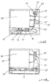
- the front section illustrated in Fig. 1 within view of the operator, shows the fluid outlets marked 1, 2, 3 for the respective instruments 1', 2', 3' (the outlets 2 and 3 are preferably fitted with Borden connector).
- the waterproof buttons for the solenoid valve selector switches are marked 4, 5, 6 and 7.
- Pressing the button 4 activates the release of fluid for the cooling spray at outlet 2 and illuminates the indicator light 11; pressing the button 5 activates the outlet 3 or outlet 2 function and illuminates the indicator light for that outlet (outlet 2: light 10, outlet 3: light 14); pressing the button 6 activates the release of fluid for the spray at outlet 3 and illuminates the light 13; pressing the button 7 activates the simultaneous use of outlets 2 and 3 (the cooling spray selection remains independent for each outlet; even if the cooling spray is disconnected, the air cooling function still remains operative).
- the safety light 16 carries the electrical current input, which is controlled by the fuses 19, 20, by means of the switch 15 which, through the transformer 30, carries the low voltage (approximately 12 V controlled by fuses 21, 22) to the solenoid valves for the programmed functions.
- a foot pedal switch 18 is connected to and activates the appliance by means of an anti-rip plug 17.
- the flow of water for the cooling spray is regulated by the rotating knob 8; the gauge 9 keeps the air pressure under visual control.
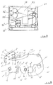
- the connector 23 is the fluid inlet (distilled water, physiological solution, disinfectant solutions) for conveyance to the tank 28 by means of the connector 23';
- the connector 24 is the connection point for the compressed air that goes to the tank at point 24' and for the outlets 2, 3 and for the triple function syringe 1' and gauge 9;
- a unidirectional valve 37 prevents the backflow of the cooling fluid from the tank to the pneumatic circuit.
- the connector 25, 25' marks the breather point for the air from the tank during filling, while the connector 26 marks the point of connection to the water mains.
- the mains water can be used to fill the tank 28 or to feed directly the cooling spray and the triple function syringe by operating the ON/OFF switch (valve) 27.
- the water circuit also includes the tank 28, the pipe unions and the pipes, the flow regulator 8, and the solenoid valves 31, 32 for the release of water for the cooling spray water outlets 3 or 2 respectively.
- the pneumatic circuit (Fig. 4) includes the unidirectional valve 37 for filling the tank 28 with compressed air, a safety valve 29 from point 29' and two solenoid valves 35, 36 for the release of air of outlets 3 and 2 respectively (for the "rotor” and for cooling) in addition to the previously mentioned gauge 9 and the water outlet connectors 33, 34, the solenoid valves 32, 31 and the triple function syringe.
- Fig. 5 shows how the circuit filtration elements can be installed in the multifunction appliance.
- 3 filtration stages 33, 34 and 35 can be installed with unidirectional valves 38 and other solenoid valves 36 and 37 connected with the use envisaged for the variations of the multifunction appliance with just two instrument outlets. Thanks to this modification the appliance can also interrupt the tool's flow of cooling air by means of the two solenoid valves 36 and 37 controlled by two other buttons located on the console.
- the overall pneumatic circuit diagram is shown schematically in Fig. 6.
- the motor compressor 17' works under suction from one or the other circuit depending on whether it takes in air through the external organic fluid collection container from the operating area (inlet 9) or atmospheric air through the filter 19'' according to the position of the commutator 7' which operates the switch 7''.
- Another function is that, when the vacuum pressure reaches a value of approximately 200 mmHg, the unidirectional valve 20' opens and part of the inducted air enters through the filter 19', while the vacuum of 200 mmHg still remains at the connector 9'.
- the collected condensate of the filters flows into the unidirectional valves unit 28' and is discharged outside through the outlet 12'.
- the unidirectional valves indicated by 31'' in the various branches of the circuit, establish a pressure and flow balance between the two motor compressors 17' and 18'.
- the optimal operating conditions are completed by other service elements such as the pressure switch 32', electrically connected to the solenoid valve 29' which, by means of the selector 30', discharges the air from inside the motor compressors and stops them when a pressure of 6 bars has been reached in the circuit.
- the pressure switch 32' electrically connected to the solenoid valve 29' which, by means of the selector 30', discharges the air from inside the motor compressors and stops them when a pressure of 6 bars has been reached in the circuit.
- a safety valve 31' against overpressure is also envisaged.
- This invention achieves the stated aims and, specifically, it enables surgeons to work in peripheral structures without the need for specific fixed equipment.
Landscapes
- Health & Medical Sciences (AREA)
- Life Sciences & Earth Sciences (AREA)
- Veterinary Medicine (AREA)
- Animal Behavior & Ethology (AREA)
- General Health & Medical Sciences (AREA)
- Public Health (AREA)
- Surgery (AREA)
- Dentistry (AREA)
- Oral & Maxillofacial Surgery (AREA)
- Epidemiology (AREA)
- Nuclear Medicine, Radiotherapy & Molecular Imaging (AREA)
- Engineering & Computer Science (AREA)
- Biomedical Technology (AREA)
- Heart & Thoracic Surgery (AREA)
- Medical Informatics (AREA)
- Molecular Biology (AREA)
- Control Of Positive-Displacement Pumps (AREA)
Applications Claiming Priority (4)
| Application Number | Priority Date | Filing Date | Title |
|---|---|---|---|
| ITBO910466 | 1991-12-11 | ||
| ITBO910466A IT1253909B (it) | 1991-12-11 | 1991-12-11 | Apparecchiatura multifunzionale mobile per impieghi chirurgici multipli |
| ITBO920144A IT1260140B (it) | 1992-04-17 | 1992-04-17 | Perfezionamento nelle apparecchiature multifunzionali mobili per impieghi chirurgici multipli |
| ITBO920144 | 1992-04-17 |
Publications (1)
| Publication Number | Publication Date |
|---|---|
| EP0548031A1 true EP0548031A1 (de) | 1993-06-23 |
Family
ID=26330267
Family Applications (1)
| Application Number | Title | Priority Date | Filing Date |
|---|---|---|---|
| EP92830662A Withdrawn EP0548031A1 (de) | 1991-12-11 | 1992-12-10 | Tragbare Multifunktionseinheit zur mehrfachen chirurgischen Verwendung |
Country Status (1)
| Country | Link |
|---|---|
| EP (1) | EP0548031A1 (de) |
Cited By (1)
| Publication number | Priority date | Publication date | Assignee | Title |
|---|---|---|---|---|
| EP1116477A1 (de) * | 1999-09-22 | 2001-07-18 | Ute Adrian | Chirurgische Werkzeugstation |
Citations (5)
| Publication number | Priority date | Publication date | Assignee | Title |
|---|---|---|---|---|
| FR2037573A5 (de) * | 1970-03-03 | 1970-12-31 | Majesco Inc | |
| US4286949A (en) * | 1980-02-15 | 1981-09-01 | Holt Jr Raleigh A | Portable dental apparatus |
| EP0094470A1 (de) * | 1982-05-17 | 1983-11-23 | Gabriel Bernaz | Tragbares Gerät für zahnärztliche Behandlung |
| EP0350459A2 (de) * | 1988-07-06 | 1990-01-10 | CASTELLINI S.p.A. | Sterilisier-Einheit für Behandlungsmedien in medizinischen Geräten, insbesondere für die Zahnchirurgie |
| US4902226A (en) * | 1988-04-29 | 1990-02-20 | Elliott Raymond D | Dental air supply system |
-
1992
- 1992-12-10 EP EP92830662A patent/EP0548031A1/de not_active Withdrawn
Patent Citations (5)
| Publication number | Priority date | Publication date | Assignee | Title |
|---|---|---|---|---|
| FR2037573A5 (de) * | 1970-03-03 | 1970-12-31 | Majesco Inc | |
| US4286949A (en) * | 1980-02-15 | 1981-09-01 | Holt Jr Raleigh A | Portable dental apparatus |
| EP0094470A1 (de) * | 1982-05-17 | 1983-11-23 | Gabriel Bernaz | Tragbares Gerät für zahnärztliche Behandlung |
| US4902226A (en) * | 1988-04-29 | 1990-02-20 | Elliott Raymond D | Dental air supply system |
| EP0350459A2 (de) * | 1988-07-06 | 1990-01-10 | CASTELLINI S.p.A. | Sterilisier-Einheit für Behandlungsmedien in medizinischen Geräten, insbesondere für die Zahnchirurgie |
Cited By (1)
| Publication number | Priority date | Publication date | Assignee | Title |
|---|---|---|---|---|
| EP1116477A1 (de) * | 1999-09-22 | 2001-07-18 | Ute Adrian | Chirurgische Werkzeugstation |
Similar Documents
| Publication | Publication Date | Title |
|---|---|---|
| US7160273B2 (en) | Suction pump | |
| US5449347A (en) | Patient transport, plural power source suction apparatus | |
| KR102263247B1 (ko) | 진공원을 구비한 이동 카트와 석션 펌프에 결합된 폐기물 컨테이너를 구비한 이동 카트를 포함하는 의료 및 수술 폐기물용 폐기물 수집 시스템 | |
| AU605399B2 (en) | Integrated unit for extracorporeal blood circuits | |
| US4276023A (en) | Fluid flow control console | |
| US5330469A (en) | Apparatus for supporting an electrosurgical generator and interfacing such with an electrosurgical pencil and an inert gas supply | |
| CA2272635C (en) | Dental scaler | |
| US6745590B1 (en) | Condensate removal system | |
| WO2002072174A3 (en) | Fluid management assembly having a vented outlet line for use in endoscopic procedures | |
| EP2097014A1 (de) | Chirurgisches schaltnetzteil und chirurgisches gleichstromelektrowerkzeug | |
| CA2378093A1 (en) | Delivery device | |
| US4086643A (en) | Combination plug and power cut-off unit | |
| US4306558A (en) | Portable liquid collection device | |
| WO2007117638A3 (en) | Iv pole attachable retractable cord power outlet | |
| US6379149B1 (en) | Dental treatment area | |
| US3553840A (en) | Mobile quick set-up self-contained orthodontic unit | |
| CN209770974U (zh) | 一种可调微创冲洗吸引装置 | |
| TWI602557B (zh) | 可搬運式牙科診療裝置 | |
| US3017886A (en) | Evacuative suction apparatus | |
| ES2255673T3 (es) | Aparato de cocina accionado con motor electrico. | |
| US6647584B2 (en) | Cleaning apparatus using vapormist spray | |
| US4958963A (en) | Mobile work station for podiatrist | |
| US3197868A (en) | Dental instrument unit | |
| CN211750108U (zh) | 一种妇科用器具消毒箱 | |
| KR100348796B1 (ko) | 배전반용 공기정화장치 |
Legal Events
| Date | Code | Title | Description |
|---|---|---|---|
| PUAI | Public reference made under article 153(3) epc to a published international application that has entered the european phase |
Free format text: ORIGINAL CODE: 0009012 |
|
| AK | Designated contracting states |
Kind code of ref document: A1 Designated state(s): AT BE CH DE DK ES FR GB GR IT LI LU NL PT SE |
|
| RBV | Designated contracting states (corrected) |
Designated state(s): AT BE CH DE ES FR GB GR IT LI LU NL PT SE |
|
| 17P | Request for examination filed |
Effective date: 19931118 |
|
| 17Q | First examination report despatched |
Effective date: 19950814 |
|
| 18D | Application deemed to be withdrawn |
Effective date: 19951228 |