EP0548068B1 - Deflecteur d'ondes monobloc pour systeme d'admission de moteur a combustion interne - Google Patents
Deflecteur d'ondes monobloc pour systeme d'admission de moteur a combustion interne Download PDFInfo
- Publication number
- EP0548068B1 EP0548068B1 EP90903154A EP90903154A EP0548068B1 EP 0548068 B1 EP0548068 B1 EP 0548068B1 EP 90903154 A EP90903154 A EP 90903154A EP 90903154 A EP90903154 A EP 90903154A EP 0548068 B1 EP0548068 B1 EP 0548068B1
- Authority
- EP
- European Patent Office
- Prior art keywords
- shaft
- wave
- clip
- runners
- wave deflector
- Prior art date
- Legal status (The legal status is an assumption and is not a legal conclusion. Google has not performed a legal analysis and makes no representation as to the accuracy of the status listed.)
- Expired - Lifetime
Links
- 238000002485 combustion reaction Methods 0.000 claims abstract description 14
- 238000005452 bending Methods 0.000 claims abstract description 4
- 238000007789 sealing Methods 0.000 claims description 2
- 230000000295 complement effect Effects 0.000 claims 1
- 239000004033 plastic Substances 0.000 abstract description 9
- 229920003023 plastic Polymers 0.000 abstract description 9
- 238000010276 construction Methods 0.000 abstract description 5
- 238000009434 installation Methods 0.000 abstract 1
- 239000000446 fuel Substances 0.000 description 11
- 239000000463 material Substances 0.000 description 5
- 238000007373 indentation Methods 0.000 description 4
- 238000000034 method Methods 0.000 description 3
- 230000015572 biosynthetic process Effects 0.000 description 2
- 238000005755 formation reaction Methods 0.000 description 2
- 230000006698 induction Effects 0.000 description 2
- 239000002184 metal Substances 0.000 description 2
- 239000000203 mixture Substances 0.000 description 2
- 230000000903 blocking effect Effects 0.000 description 1
- 230000000994 depressogenic effect Effects 0.000 description 1
- 238000011900 installation process Methods 0.000 description 1
- 230000000717 retained effect Effects 0.000 description 1
- 239000007921 spray Substances 0.000 description 1
- 238000011144 upstream manufacturing Methods 0.000 description 1
Images


Classifications
-
- F—MECHANICAL ENGINEERING; LIGHTING; HEATING; WEAPONS; BLASTING
- F02—COMBUSTION ENGINES; HOT-GAS OR COMBUSTION-PRODUCT ENGINE PLANTS
- F02B—INTERNAL-COMBUSTION PISTON ENGINES; COMBUSTION ENGINES IN GENERAL
- F02B27/00—Use of kinetic or wave energy of charge in induction systems, or of combustion residues in exhaust systems, for improving quantity of charge or for increasing removal of combustion residues
- F02B27/02—Use of kinetic or wave energy of charge in induction systems, or of combustion residues in exhaust systems, for improving quantity of charge or for increasing removal of combustion residues the systems having variable, i.e. adjustable, cross-sectional areas, chambers of variable volume, or like variable means
- F02B27/0226—Use of kinetic or wave energy of charge in induction systems, or of combustion residues in exhaust systems, for improving quantity of charge or for increasing removal of combustion residues the systems having variable, i.e. adjustable, cross-sectional areas, chambers of variable volume, or like variable means characterised by the means generating the charging effect
- F02B27/0247—Plenum chambers; Resonance chambers or resonance pipes
- F02B27/0263—Plenum chambers; Resonance chambers or resonance pipes the plenum chamber and at least one of the intake ducts having a common wall, and the intake ducts wrap partially around the plenum chamber, i.e. snail-type
-
- F—MECHANICAL ENGINEERING; LIGHTING; HEATING; WEAPONS; BLASTING
- F02—COMBUSTION ENGINES; HOT-GAS OR COMBUSTION-PRODUCT ENGINE PLANTS
- F02B—INTERNAL-COMBUSTION PISTON ENGINES; COMBUSTION ENGINES IN GENERAL
- F02B27/00—Use of kinetic or wave energy of charge in induction systems, or of combustion residues in exhaust systems, for improving quantity of charge or for increasing removal of combustion residues
- F02B27/02—Use of kinetic or wave energy of charge in induction systems, or of combustion residues in exhaust systems, for improving quantity of charge or for increasing removal of combustion residues the systems having variable, i.e. adjustable, cross-sectional areas, chambers of variable volume, or like variable means
-
- F—MECHANICAL ENGINEERING; LIGHTING; HEATING; WEAPONS; BLASTING
- F02—COMBUSTION ENGINES; HOT-GAS OR COMBUSTION-PRODUCT ENGINE PLANTS
- F02B—INTERNAL-COMBUSTION PISTON ENGINES; COMBUSTION ENGINES IN GENERAL
- F02B27/00—Use of kinetic or wave energy of charge in induction systems, or of combustion residues in exhaust systems, for improving quantity of charge or for increasing removal of combustion residues
- F02B27/02—Use of kinetic or wave energy of charge in induction systems, or of combustion residues in exhaust systems, for improving quantity of charge or for increasing removal of combustion residues the systems having variable, i.e. adjustable, cross-sectional areas, chambers of variable volume, or like variable means
- F02B27/0226—Use of kinetic or wave energy of charge in induction systems, or of combustion residues in exhaust systems, for improving quantity of charge or for increasing removal of combustion residues the systems having variable, i.e. adjustable, cross-sectional areas, chambers of variable volume, or like variable means characterised by the means generating the charging effect
- F02B27/0268—Valves
- F02B27/0273—Flap valves
-
- F—MECHANICAL ENGINEERING; LIGHTING; HEATING; WEAPONS; BLASTING
- F02—COMBUSTION ENGINES; HOT-GAS OR COMBUSTION-PRODUCT ENGINE PLANTS
- F02D—CONTROLLING COMBUSTION ENGINES
- F02D9/00—Controlling engines by throttling air or fuel-and-air induction conduits or exhaust conduits
- F02D9/08—Throttle valves specially adapted therefor; Arrangements of such valves in conduits
- F02D9/10—Throttle valves specially adapted therefor; Arrangements of such valves in conduits having pivotally-mounted flaps
- F02D9/109—Throttle valves specially adapted therefor; Arrangements of such valves in conduits having pivotally-mounted flaps having two or more flaps
- F02D9/1095—Rotating on a common axis, e.g. having a common shaft
-
- F—MECHANICAL ENGINEERING; LIGHTING; HEATING; WEAPONS; BLASTING
- F02—COMBUSTION ENGINES; HOT-GAS OR COMBUSTION-PRODUCT ENGINE PLANTS
- F02B—INTERNAL-COMBUSTION PISTON ENGINES; COMBUSTION ENGINES IN GENERAL
- F02B27/00—Use of kinetic or wave energy of charge in induction systems, or of combustion residues in exhaust systems, for improving quantity of charge or for increasing removal of combustion residues
- F02B27/02—Use of kinetic or wave energy of charge in induction systems, or of combustion residues in exhaust systems, for improving quantity of charge or for increasing removal of combustion residues the systems having variable, i.e. adjustable, cross-sectional areas, chambers of variable volume, or like variable means
- F02B27/0205—Use of kinetic or wave energy of charge in induction systems, or of combustion residues in exhaust systems, for improving quantity of charge or for increasing removal of combustion residues the systems having variable, i.e. adjustable, cross-sectional areas, chambers of variable volume, or like variable means characterised by the charging effect
- F02B27/0215—Oscillating pipe charging, i.e. variable intake pipe length charging
-
- F—MECHANICAL ENGINEERING; LIGHTING; HEATING; WEAPONS; BLASTING
- F02—COMBUSTION ENGINES; HOT-GAS OR COMBUSTION-PRODUCT ENGINE PLANTS
- F02D—CONTROLLING COMBUSTION ENGINES
- F02D9/00—Controlling engines by throttling air or fuel-and-air induction conduits or exhaust conduits
- F02D9/08—Throttle valves specially adapted therefor; Arrangements of such valves in conduits
- F02D9/10—Throttle valves specially adapted therefor; Arrangements of such valves in conduits having pivotally-mounted flaps
- F02D9/107—Manufacturing or mounting details
-
- F—MECHANICAL ENGINEERING; LIGHTING; HEATING; WEAPONS; BLASTING
- F05—INDEXING SCHEMES RELATING TO ENGINES OR PUMPS IN VARIOUS SUBCLASSES OF CLASSES F01-F04
- F05C—INDEXING SCHEME RELATING TO MATERIALS, MATERIAL PROPERTIES OR MATERIAL CHARACTERISTICS FOR MACHINES, ENGINES OR PUMPS OTHER THAN NON-POSITIVE-DISPLACEMENT MACHINES OR ENGINES
- F05C2225/00—Synthetic polymers, e.g. plastics; Rubber
- F05C2225/08—Thermoplastics
-
- Y—GENERAL TAGGING OF NEW TECHNOLOGICAL DEVELOPMENTS; GENERAL TAGGING OF CROSS-SECTIONAL TECHNOLOGIES SPANNING OVER SEVERAL SECTIONS OF THE IPC; TECHNICAL SUBJECTS COVERED BY FORMER USPC CROSS-REFERENCE ART COLLECTIONS [XRACs] AND DIGESTS
- Y02—TECHNOLOGIES OR APPLICATIONS FOR MITIGATION OR ADAPTATION AGAINST CLIMATE CHANGE
- Y02T—CLIMATE CHANGE MITIGATION TECHNOLOGIES RELATED TO TRANSPORTATION
- Y02T10/00—Road transport of goods or passengers
- Y02T10/10—Internal combustion engine [ICE] based vehicles
- Y02T10/12—Improving ICE efficiencies
-
- Y—GENERAL TAGGING OF NEW TECHNOLOGICAL DEVELOPMENTS; GENERAL TAGGING OF CROSS-SECTIONAL TECHNOLOGIES SPANNING OVER SEVERAL SECTIONS OF THE IPC; TECHNICAL SUBJECTS COVERED BY FORMER USPC CROSS-REFERENCE ART COLLECTIONS [XRACs] AND DIGESTS
- Y10—TECHNICAL SUBJECTS COVERED BY FORMER USPC
- Y10T—TECHNICAL SUBJECTS COVERED BY FORMER US CLASSIFICATION
- Y10T137/00—Fluid handling
- Y10T137/0318—Processes
- Y10T137/0402—Cleaning, repairing, or assembling
-
- Y—GENERAL TAGGING OF NEW TECHNOLOGICAL DEVELOPMENTS; GENERAL TAGGING OF CROSS-SECTIONAL TECHNOLOGIES SPANNING OVER SEVERAL SECTIONS OF THE IPC; TECHNICAL SUBJECTS COVERED BY FORMER USPC CROSS-REFERENCE ART COLLECTIONS [XRACs] AND DIGESTS
- Y10—TECHNICAL SUBJECTS COVERED BY FORMER USPC
- Y10T—TECHNICAL SUBJECTS COVERED BY FORMER US CLASSIFICATION
- Y10T137/00—Fluid handling
- Y10T137/8593—Systems
- Y10T137/87153—Plural noncommunicating flow paths
- Y10T137/87161—With common valve operator
Definitions
- This invention relates generally to internal combustion (I.C.) engine intake systems, and in particular it relates to a novel wave deflector for use in tuned runners to the individual cylinders.
- I.C. internal combustion
- a known construction for an I.C. engine intake system comprises the use of tuned runners leading to the individual cylinders and wave deflectors disposed in association with the runners.
- the wave deflectors are selectively operable to de-select a particular set of runners under certain operating conditions so that air is conducted to the cylinders through a differently tuned set of runners.
- each such set can be independently de-selected.
- a wave deflector is poised at the cylinder end of a runner. It is operable to open and closed positions, opening and closing the associated runner. De-selection of a runner occurs when the corresponding wave deflector is closed.
- a closed wave deflector blocks, or deflects, the pressure wave that emanates from the corresponding cylinder when the piston within the cylinder is executing the intake stroke.
- the known construction for a wave deflector comprises a metal shaft that passes through aligned circular holes in walls separating the runners which extend to adjacent cylinders. Metal blades that form the deflectors are fastened to the shaft. This construction is expensive because it uses a number of individual parts and requires a significant amount of assembly. Moreover, if one of the parts should break away, it could enter the engine cylinder and create undesired consequences.
- EP-A-0 235 288, shows a monolithic valve assembly aimed at selectively closing an air inlet passage.
- the present invention arises through the recognition that a precise fit of a wave deflector to an associated runner is not essential for the purpose of accomplishing the wave deflection function. In other words, when a wave deflector is closed, it is not essential that the edge of the wave deflector be perfectly sealed with respect to the wall of its runner.
- the invention contemplates a one piece wave deflector made of plastic materials which make the deflector element resiliently bendable so that it can be installed better than a metall piece construction.
- the disclosed plastic wave deflector element has slots between the wave deflectors and the shaft that facilitates bending during the installation process.
- the disclosed wave deflector element spans the runners to two adjacent cylinders.
- the ends of the element are part of the shaft, and they are fitted to circular holes in respective walls of the runners.
- the runners share a common wall, and an intermediate portion of the element's shaft must pass through this common wall.
- the common wall comprises a slot.
- a clip that journals the intermediate portion of the shaft is fitted to this slot.
- the shaft, the clip, and the slot are constructed and arranged such that the wave deflector element is accurately axially located and there is substantial closure of the slot between the two adjacent runners so that there is no cross flow between these runners.
- FIGURE 1 is a transverse cross-sectional view through an internal combustion engine intake system including the novel wave deflector element of the present invention.
- FIGURE 2 is a fragmentary view showing an alternate embodiment.
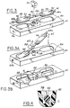
- FIGURE 3 is a fragmentary exploded perspective view illustrating a wave deflector element and related parts.
- FIGURE 3A is a view similar to FIGURE 3 illustrating the manner of assembly of the parts of FIGURE 3.
- FIGURE 3B is a view similar to FIGURES 3 and 3A illustrating the final assembled position.
- FIGURE 4 is a transverse cross-sectional view on an enlarged scale in the direction of arrows 4-4 in FIGURE 3B.
- FIGURE 5 is a perspective view of one of the component parts of FIGURE 3 shown by itself.
- FIGURE 6 is a view similar to FIGURE 5 but illustrating an alternate form.
- FIGURE 7 is a view taken in the same direction as FIGURE 4 but illustrating the part of FIGURE 6 in operative association with a wave deflector element in the installed position.
- FIGURE 8 is a fragmentary view illustrating one end mounting of the wave deflector element.
- FIGURE 9 is a fragmentary sectional view illustrating another end mounting of the wave deflector element.
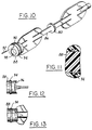
- FIGURE 10 is an exploded prospective view illustrating an alternate embodiment of wave deflector element.
- FIGURE 11 is a transverse cross-sectional view on an enlarged scale through the near end portion of FIGURE 10.
- FIGURE 12 is a fragmentary view of an alternate configuration for an end of a wave deflector.
- FIGURE 13 is a view similar to FIGURE 12 but with the wave deflector rotated ninety degrees about its own axis.
- FIGURE 1 is a cross-section through a representative intake system 20 of an internal combustion engine.
- the engine is also representative and by way of example is a four-cylinder gasoline fueled engine. Only the engine cylinder head 22 and an associated intake valve mechanism 24 for one cylinder of the engine are shown in FIGURE 1. It can therefore be appreciated that the cross-sectional view of FIGURE 1 is through the intake port 26 that leads into the engine cylinder, the intake port being opened to the cylinder whenever the intake valve 24 is opened.
- the airflow path through intake system 20 is represented by the arrows 28.
- Induction air that enters intake system 20 first passes through a main throttle valve 30 which is under the control of an operator to set the degree of throttle blade opening. From there the airflow passes to a plenum region 32 which extends lengthwise of the intake system 20, the length of system 20 being perpendicular to the plane of FIG. 1.
- a main throttle valve 30 which is under the control of an operator to set the degree of throttle blade opening. From there the airflow passes to a plenum region 32 which extends lengthwise of the intake system 20, the length of system 20 being perpendicular to the plane of FIG. 1.
- FIG. 1 shows the two runners 34, 36 that lead to one cylinder.
- the runners extend to the intake port 26, communicating the plenum 32 to the intake port.
- An electromagnetic fuel injector 38 is located in a fuel rail block 40.
- the injector is operated in suitably timed relation to spray fuel into intake port 26 for mixture with the air that has passed through the intake system to thereby form a combustible mixture that is introduced into the engine cylinder when valve 24 is open.
- a wave deflector element 42 is disposed in association with runner 36 just upstream of the intake valve mechanism 24.
- FIGURE 1 shows the wave deflector element 42 in closed position. In this condition induction air to the cylinder passes through runner 34 and not through runner 36.
- the wave deflector serves to block, or deflect, the pressure wave that emanates from the cylinder when the piston within the cylinder is executing the intake stroke.
- FIGURE 2 shows two wave deflector elements 42, one in association with runner 34, the other with runner 36.
- FIGS. 3, 3A, AND 3B portray a representative wave deflector element 42 that embodies principles of the invention.
- the wave deflector element is a one-piece plastic part and comprises a shaft 44 and a pair of wave deflectors 46, 48.
- the shaft and wave deflectors are integrally formed from plastic so as to constitute a single partr
- the wave deflectors 46, 48 are flat.
- the shaft comprises circular end portions 44a and 44b and a circular intermediate portion 44c.
- a recessed shoulder 50 is provided at the middle of portion 44c.
- the shaft may be considered flat as it passes across each wave deflector.
- Four slits 52 are provided in each wave deflector alongside where the flattened shaft passes across. Slits 52 are parallel to the shaft each beginning at an edge of each wave deflector and extending partially across the wave deflector. There are two slits in alignment with each other on one side of the shaft and two more in alignment with each other on the opposite side of the shaft. The purpose of the slits 52 is to facilitate flexing of the wave deflector element shaft when the wave deflector element is assembled to fuel rail block 40 in the manner that will now be described with reference to FIGS. 3A and 3B.
- the wave deflector material comprises any suitable plastic which is resiliently bendable. Assembly of the wave deflector element to the fuel rail block is accomplished in the following manner. First, the fuel rail block 40 is provided with suitable formations constituting the terminations of the respective runners with which the two wave deflectors 46 and 48 are disposed. The wave deflector 48 is associated with the runner 36 leading to one engine intake port 26 while the other wave deflector 46 is associated with the intake port 26 and the runner 36 of the immediately adjacent cylinder.
- a pair of aligned circular holes 54 and 56 are provided in walls of fuel rail block 40.
- a plastic clip 58 is assembled onto shoulder 50. Assembly of the wave deflector element to the fuel rail block is accomplished by inserting the shaft end 44b into hole 56 in the manner shown in FIG. 3A. At this time the wave deflector element is flexed in the manner shown. Thereafter the shaft is flexed into more of an S shape as represented by the arrows 60 and 62 respectively, and the shaft end 44a is brought into alignment with and inserted into hole 54.
- clip 58 is being disposed in a T-shaped slot 64 that is transverse to a U-shaped slot 66 within which the central portion 44c of the shaft 44 is disposed.
- the final assembled position is portrayed in FIG. 3B.
- the shape of clip 58 is perhaps best seen in FIG. 5.
- the clip has a general T-shape and comprises a circular hole 68 for fitting onto shaft 44.
- the diameter of hole 68 is one that will fit closely for embracing shoulder 50.
- the hole 68 is only a partial one, however, since a throat 70 is provided in the bottom of the clip intercepting hole 68.
- the throat coupled with the resilient flexibility of the material of the clip enables the clip to be snapped onto the shaft.
- FIGURE 4 it also shows that the clip and the shaft substantially fill the slot 64 so as to block any leak path between the two runners with which the respective wave deflectors 46 and 48 are associated.
- FIGURE 4 It can be seen in FIGURE 4 that there is a land 71 which fills the throat 70 of the clip. It will be observed that with the clip disposed in slot 64 the clip cannot be flexed open and thereby serves to embrace shaft 44. Moreover, the clip serves to axially locate the wave deflector element between holes 54 and 56. It will also be observed that the shaft end 44b is somewhat longer than the shaft end 44a to facilitate the assembly process.
- the wave deflectors do not have a perfect fit within their respective runners. This, however, is not critical because it has been found that substantial closure of a runner is effective to perform the wave deflection function.
- the ends 44a, 44b of the shaft have a sufficiently close fit with holes 54, 56 so that leakage through these points is not a problem.
- the wave deflector element is operated by an actuator (not shown) and the actuator in turn is controlled by an electronic control unit (ECU).
- the wave deflectors are operated between open and closed positions that are approximately ninety degrees apart. In the closed position, the wave deflectors are perpendicular to the flow through the runners and in the open position they are parallel to the flow.
- the embodiment of clip and shaft shown in FIGS. 5, 6 and 7 comprises a detent mechanism for defining these two open and closed positions.
- the clip is provided with a spring leaf 72 that bears against the side of the shaft.
- the shaft is provided with a bump 73, and the inside of hole 68 is provided with two indentations 74 and 76 that are ninety degrees apart.
- the spring leaf 72 urges the bump 73 against the wall of hole 68 that lies between indentations 74 and 76.
- the bump fits into one of the indentations 74, 76 and when the wave deflectors are fully open it fits into the other indentation.
- the detent mechanism tends to favor the positioning of the wave deflectors in either the open or closed position as distinguished from any intermediate position; however, they do not unduly restrict the ability of the actuator to move the wave deflectors between the open and closed positions.
- FIG. 8 shows an arrangement for operating the wave deflector element.
- the operating arrangement involves making the end 44b sufficiently long that it protrudes through the hole 56 and attaching a lever 78 to the protruding end.
- the lever has a non-circular hole fitting onto a reduced diameter portion at the end of the shaft and is retained between a shoulder formed in the shaft end and a snap retaining ring 80 that is fitted onto the reduced diameter shaft end.
- a connection may be made to the opposite end 44a of the shaft by providing that opposite end with a hole and passing a pin 82 through the hole in the fuel rail wall into the hole in the end of the shaft.
- the pin 82 has a sufficient length that it protrudes through the hole in the wall, and a cap 84 is fitted over the end of the pin 82.
- FIGS. 10-13 show a further embodiment 86 of a wave deflector element.
- This element comprises an integral actuator at the near end as viewed in FIG. 10.
- the actuator is in the form of a cylinder 88 that is coaxial with the element's axis.
- the circular enlargement contains a small hole 90 that is offset from the element's axis.
- the holes into which the element is mounted are suitably shaped to receive the smaller far end of the shaft as viewed in FIG. 10 and cylinder 88.
- a pin 92 is pressed into hole 90 and this pin can be connected to the actuator for actuating the wave deflector element.
- the pin and hole are eccentric and form a lever.
- a further feature is that a circular lip seal 94 is provided around the outside of cylinder 88. The lip seal makes contact with the inside wall of the hole within which cylinder 88 is mounted.
- a still further feature is that the face of cylinder 88 that is toward the adjacent wave deflector contains a profile 96 corresponding to an immediately contiguous portion of the transverse cross-section of the runner within which that wave deflector is disposed such that when the wave deflector is opening the runner, the cylinder presents no discontinuity to flow through the runner. This condition is most readily seen in FIG. 12.
- the cylinder 88 contains a hole in the end to save on material used in making the wave deflector.
- a further difference in element 86 is that the shoulder 50 in the center of the shaft is raised, rather than being depressed. It will be understood that certain changes are made in clip 58 to accommodate the raised shoulder.
- any plastic that is resiliently bendable and can withstand the moderately elevated temperatures to which the wave deflectors will be exposed (200 degrees F is typical) is suitable.
- moderately elevated temperatures to which the wave deflectors will be exposed 200 degrees F is typical
Landscapes
- Engineering & Computer Science (AREA)
- Chemical & Material Sciences (AREA)
- Combustion & Propulsion (AREA)
- Mechanical Engineering (AREA)
- General Engineering & Computer Science (AREA)
- Characterised By The Charging Evacuation (AREA)
- Control Of Throttle Valves Provided In The Intake System Or In The Exhaust System (AREA)
Abstract
Claims (10)
- Un moteur à combustion interne comprenant des conduits (34, 36) à travers lesquels circule de l'air qui passe d'un mécanisme de papillon d'accélérateur (30) vers des soupapes d'admission (24) de cylindres, et un mécanisme de déflecteurs d'ondes (42) qui est monté de façon tournante sur le moteur pour accomplir un mouvement de rotation autour d'un axe, ce mécanisme de déflecteurs d'onde comprenant un axe (44) qui coîncide avec l'axe précité et qui s'étend transversalement d'un côté à l'autre des conduits (34, 36), et des déflecteurs d'ondes (46, 48) qui sont montés sur l'axe (44) et tournent sous l'action de ce dernier, pour ouvrir et fermer sélectivement les conduits, cet axe ayant un rayon donné, les déflecteurs d'ondes ayant une étendue radiale qui est supérieure à ce rayon donné, les déflecteurs d'ondes (46, 48) et l'axe (44) étant formés en une seule pièce, caractérisé en ce que l'axe peut être dévié de façon élastique par rapport aux déflecteurs d'ondes, en étant courbé, et en ce qu'une bride de retenue séparée (58) qui vient en contact et coopère avec une paroi qui sépare les conduits, est montée à cheval sur l'axe.
- Un moteur à combustion interne selon la revendication 1, caractérisé en outre en ce que les déflecteurs d'ondes (46, 48) sont mutuellement espacés sur la longueur de l'axe (44), cet axe traverse une encoche (64) dans la paroi qui sépare les conduits, la bride et l'encoche sont réalisées et disposées de façon à fermer pratiquement l'encoche entre les conduits, la bride comporte un étranglement (70) que l'on peut ouvrir en l'élargissant pour permettre de pousser la bride sur l'axe dans une direction radiale de l'axe, avant l'assemblage de la bride et du mécanisme de déflecteurs d'ondes dans les conduits, l'encoche ayant une forme complémentaire de celle de la bride, de façon qu'une fois que le mécanisme de déflecteurs d'ondes a été installé avec la bride disposée dans l'encoche, la bride ne puisse plus s'ouvrir en s'élargissant, pour retenir ainsi la bride sur l'axe.
- Un moteur à combustion interne selon la revendication 2, caractérisé en outre en ce que la bride et l'axe ont un mécanisme à déclic (73, 74, 76) qui favorise deux positions en rotation discrètes de l'axe, et ces positions définissent respectivement l'ouverture complète et la fermeture complète des déflecteurs d'ondes.
- Un moteur à combustion interne selon la revendication 2, caractérisé en outre en ce qu'un épaulement (50) est formé dans l'axe pour positionner ce dernier en direction axiale par rapport à la bride, et l'encoche a une forme conçue pour positionner axialement la bride.
- Un moteur à combustion interne selon la revendication 1, caractérisé en outre en ce que des fentes (52) qui séparent des parties des déflecteurs d'ondes vis-à-vis de l'axe, sont formées pour permettre de courber l'axe plus facilement.
- Un moteur à combustion interne selon la revendication 5, caractérisé en outre en ce que les fentes sont parallèles à l'axe, chaque fente commence à un bord de chaque déflecteur d'ondes et elle s'étend partiellement sur l'étendue de chaque déflecteur d'ondes, et il y a quatre fentes par déflecteur d'ondes, deux en alignement mutuel d'un côté de l'axe, et deux supplémentaires en alignement mutuel du côté opposé de l'axe.
- Un moteur à combustion interne selon la revendication 1, caractérisé en outre en ce que des extrémités opposées (44a, 44b) de l'axe sont montées de façon tournante dans des parois respectives du moteur, l'une de ces extrémités comportant un excentrique formé en une seule pièce (88, 90) par l'intermédiaire duquel on fait tourner l'axe.
- Un moteur à combustion interne selon la revendication 1, caractérisé en outre en ce que des extrémités opposées (44a, 44b) de l'axe sont montées de façon tournante dans des parois respectives du moteur, l'une de ces extrémités d'axe comprenant une lèvre d'étanchéité circulaire (94) formée en une seule pièce avec l'extrémité d'axe considéré et s'étendant autour de cette dernière de façon à définir un joint d'étanchéité entre elle et la paroi particulière dans laquelle cette extrémité d'axe est montée de façon tournante.
- Un moteur à combustion interne selon la revendication 1, caractérisé en ce qu'une première extrémité (44a) de l'axe s'ajuste dans un trou borgne (54) dans une première paroi du moteur, l'autre extrémité (44b) de l'axe s'ajuste dans un trou traversant (56) dans une seconde paroi du moteur, et la première extrémité de l'axe est plus courte que la seconde extrémité de l'axe.
- Un moteur à combustion interne selon la revendication 1, caractérisé en outre en ce que des extrémités opposées de l'axe sont montées de façon tournante dans des parois respectives du moteur, l'une des extrémités de l'axe comporte une forme cylindrique (88), et la face d'extrémité (96) de cette forme cylindrique qui est du côté du conduit le plus proche de la paire de conduits présente un profil correspondant à une partie immédiatement contiguë de la section transversale de ce conduit plus proche, de façon que lorsque que le déflecteur d'ondes particulier qui commande ce conduit plus proche ouvre ce dernier, l'extrémité précitée parmi les extrémités de l'axe ne présente aucune discontinuité pour l'écoulement à travers ce conduit plus proche.
Applications Claiming Priority (3)
| Application Number | Priority Date | Filing Date | Title |
|---|---|---|---|
| US313645 | 1989-02-21 | ||
| US07/313,645 US4907547A (en) | 1989-02-21 | 1989-02-21 | One-piece wave deflector for I.C. engine intake system |
| PCT/EP1990/000262 WO1990010144A1 (fr) | 1989-02-21 | 1990-02-16 | Deflecteur d'ondes monobloc pour systeme d'admission de moteur a combustion interne |
Publications (2)
| Publication Number | Publication Date |
|---|---|
| EP0548068A1 EP0548068A1 (fr) | 1993-06-30 |
| EP0548068B1 true EP0548068B1 (fr) | 1994-08-31 |
Family
ID=23216531
Family Applications (1)
| Application Number | Title | Priority Date | Filing Date |
|---|---|---|---|
| EP90903154A Expired - Lifetime EP0548068B1 (fr) | 1989-02-21 | 1990-02-16 | Deflecteur d'ondes monobloc pour systeme d'admission de moteur a combustion interne |
Country Status (8)
| Country | Link |
|---|---|
| US (1) | US4907547A (fr) |
| EP (1) | EP0548068B1 (fr) |
| JP (1) | JP2980674B2 (fr) |
| KR (1) | KR0127339B1 (fr) |
| CA (1) | CA1336252C (fr) |
| DE (1) | DE69012150T2 (fr) |
| ES (1) | ES2060145T3 (fr) |
| WO (1) | WO1990010144A1 (fr) |
Families Citing this family (59)
| Publication number | Priority date | Publication date | Assignee | Title |
|---|---|---|---|---|
| US5005532A (en) * | 1989-02-22 | 1991-04-09 | Siemens-Bendix Automotive Electronics Limited | Integrated tuned induction system |
| US5074257A (en) * | 1989-07-21 | 1991-12-24 | Yamaha Hatsudoki Kabushiki Kaisha | Air intake device for an engine |
| US5022371A (en) * | 1989-09-29 | 1991-06-11 | Siemens-Bendix Automotive Electronics L.P. | Molded plastic fuel rail for an internal combustion engine |
| JPH0681719A (ja) * | 1992-08-31 | 1994-03-22 | Hitachi Ltd | 内燃機関の吸気装置 |
| USRE37269E1 (en) | 1992-08-31 | 2001-07-10 | Hitachi, Ltd. | Air intake arrangement for internal combustion engine |
| AU668740B2 (en) * | 1992-09-30 | 1996-05-16 | Outboard Marine Corporation | Two-stroke internal combustion engine with improved air intake system |
| US5273016A (en) * | 1992-09-30 | 1993-12-28 | Outboard Marine Corporation | Throttle lever position sensor for two-stroke fuel injected engine |
| DE4499626T1 (de) * | 1993-12-10 | 1996-02-22 | Mitsubishi Motors Corp | Ansaugsteuervorrichtung für einen Mehrzylinder-Verbrennungsmotor |
| JP3329935B2 (ja) * | 1994-04-28 | 2002-09-30 | 株式会社日立製作所 | 内燃機関の吸気装置 |
| DE4420931C1 (de) * | 1994-06-16 | 1995-06-29 | Daimler Benz Ag | Saugrohr für einen Verbrennungsmotor |
| KR200152903Y1 (ko) * | 1994-08-25 | 1999-08-02 | 정몽규 | 내연기관의 흡기조절장치 |
| DE9415977U1 (de) * | 1994-10-05 | 1994-12-01 | Hahn, Karlheinz, 94315 Straubing | Drosselklappenanordnung |
| US5454357A (en) * | 1994-12-12 | 1995-10-03 | General Motors Corporation | Slide port valve for an internal combustion engine |
| DE19504382A1 (de) * | 1995-02-10 | 1996-08-14 | Mann & Hummel Filter | Ansaugsystem |
| DE19510622A1 (de) * | 1995-03-23 | 1996-09-26 | Bosch Gmbh Robert | Drosselvorrichtung und Verfahren zur Herstellung einer Drosselvorrichtung |
| US5875758A (en) * | 1995-04-06 | 1999-03-02 | E. I. Du Pont De Nemours And Company | Resin air intake system provided with intake control valve |
| DE19521025A1 (de) * | 1995-06-13 | 1996-12-19 | Mann & Hummel Filter | Rohrmodul |
| DE19525086C1 (de) * | 1995-07-10 | 1996-10-10 | Daimler Benz Ag | Ansaugluftleitung für einen Verbrennungsmotor |
| US5704325A (en) * | 1996-06-28 | 1998-01-06 | Basf Corporation | Stacked snail-type manifold |
| US5655492A (en) * | 1996-06-28 | 1997-08-12 | Basf Corporation | Labyrinth manifold |
| US6460563B2 (en) * | 1996-08-29 | 2002-10-08 | Olson Irrigation Systems | Irrigation system apparatus, and related method |
| US5715782A (en) * | 1996-08-29 | 1998-02-10 | Genral Motors Corporation | Composite molded butterfly valve for an internal combustion engine |
| US5713323A (en) * | 1996-10-04 | 1998-02-03 | Ford Motor Company | Integrated air/fuel induction system for an internal combustion engine |
| JP3451589B2 (ja) * | 1997-03-28 | 2003-09-29 | 有限会社日高エンジニアリング | 内燃機関の吸気装置 |
| EP0977936B1 (fr) | 1997-04-24 | 2002-06-12 | Siemens Aktiengesellschaft | Dispositif d'aspiration |
| US6026782A (en) * | 1997-10-01 | 2000-02-22 | Siemens Canada Limited | Throttle body and bracket arrangement |
| DE19918777A1 (de) * | 1999-04-24 | 2000-10-26 | Mann & Hummel Filter | Schaltklappenverband aus montagegespritzten Schaltklappen oder Klappenmodulen |
| DE29916333U1 (de) * | 1999-09-16 | 2000-01-13 | Montaplast GmbH, 51597 Morsbach | Lagervorrichtung |
| DE19946861C2 (de) * | 1999-09-30 | 2001-07-26 | Audi Ag | Ansaugsystem einer Brennkraftmaschine |
| RU2187667C2 (ru) * | 2000-07-17 | 2002-08-20 | Открытое акционерное общество "АВТОВАЗ" | Многоцилиндровый двигатель внутреннего сгорания |
| RU2187668C2 (ru) * | 2000-07-17 | 2002-08-20 | Открытое акционерное общество "АВТОВАЗ" | Многоцилиндровый двигатель внутреннего сгорания |
| US6886532B2 (en) * | 2001-03-13 | 2005-05-03 | Nissan Motor Co., Ltd. | Intake system of internal combustion engine |
| DE10119280A1 (de) * | 2001-04-20 | 2002-11-07 | Mann & Hummel Filter | Ansaugvorrichtung |
| DE10126063B4 (de) * | 2001-05-28 | 2004-07-15 | Montaplast Gmbh | Klappenvorrichtung |
| RU2209336C2 (ru) * | 2001-09-12 | 2003-07-27 | Открытое акционерное общество "АВТОВАЗ" | Двигатель внутреннего сгорания |
| RU2218466C2 (ru) * | 2001-11-05 | 2003-12-10 | Открытое акционерное общество "АВТОВАЗ" | Многоцилиндровый двигатель внутреннего сгорания |
| US6763802B1 (en) | 2002-11-25 | 2004-07-20 | Hayes Lemmerz International, Inc. | Intake manifold valve system |
| US7191748B2 (en) * | 2003-02-13 | 2007-03-20 | Siemens Canada Limited | Integrated air and fuel carrier module |
| DE10348361B4 (de) * | 2003-10-17 | 2016-02-04 | Volkswagen Ag | Saugrohr für eine Brennkraftmaschine |
| DE102004002641B4 (de) * | 2004-01-19 | 2017-01-26 | GM Global Technology Operations LLC (n. d. Ges. d. Staates Delaware) | Modulare Ansaugvorrichtung |
| DE102004004000B4 (de) * | 2004-01-26 | 2013-08-29 | Volkswagen Ag | Brennkraftmaschine mit einem Saugrohr |
| US7201141B2 (en) * | 2004-02-02 | 2007-04-10 | Ford Motor Company | Apparatus for controlling throttle shaft deflection and friction in dual bore throttle bodies |
| DE102004010555B4 (de) * | 2004-03-04 | 2006-02-09 | Pierburg Gmbh | Klappenlagerbefestigung |
| DE102004021125A1 (de) * | 2004-04-29 | 2005-12-01 | Mann + Hummel Gmbh | Klappenanordnung im Flanschbereich eines Ansaugsystems einer Brennkraftmaschine |
| US20070017472A1 (en) * | 2005-07-20 | 2007-01-25 | Siemens Vdo Automotive Inc. | Active intake and induction system |
| FR2895453B1 (fr) * | 2005-12-23 | 2011-02-18 | Renault Sas | Dispositif de repartition et d'admission d'un moteur a combustion interne, permettant de faire varier l'aerodynamique |
| DE202006007545U1 (de) * | 2006-05-10 | 2007-09-13 | Mann+Hummel Gmbh | Vorrichtung zur Steuerung der Ansaugluft für einen Verbrennungsmotor |
| DE202006018186U1 (de) * | 2006-11-29 | 2008-04-10 | Mann + Hummel Gmbh | Stellwelle in einer Brennkraftmaschine |
| DE202007013719U1 (de) * | 2007-10-01 | 2009-02-19 | Mann+Hummel Gmbh | Vorrichtung mit zwei eine gemeinsame Längsachse aufweisenden und miteinander verbundenen Kunststoff-Bauteilen |
| US8028677B2 (en) * | 2008-09-09 | 2011-10-04 | Mark Iv Systemes Moteurs Usa, Inc. | Assembly and method for controlling an air intake runner |
| US8151754B2 (en) * | 2008-09-16 | 2012-04-10 | Kawasaki Jukogyo Kabushiki Kaisha | Air-intake duct and air-intake structure |
| JP5243288B2 (ja) | 2009-02-02 | 2013-07-24 | 愛三工業株式会社 | 軸受装置 |
| KR101145630B1 (ko) * | 2009-12-03 | 2012-05-16 | 기아자동차주식회사 | 엔진의 흡기 시스템 |
| JP6277879B2 (ja) * | 2014-06-19 | 2018-02-14 | トヨタ紡織株式会社 | 内燃機関の吸気マニホルド |
| DE102015204605B4 (de) * | 2015-03-13 | 2019-07-18 | Mahle International Gmbh | Saugmodul einer Frischluftanlage |
| DE102015204604A1 (de) * | 2015-03-13 | 2016-09-15 | Mahle International Gmbh | Saugmodul einer Frischluftanlage |
| JP6558156B2 (ja) * | 2015-09-03 | 2019-08-14 | アイシン精機株式会社 | 吸気装置および吸気制御弁 |
| US9897051B2 (en) * | 2015-10-20 | 2018-02-20 | Hyundai Motor Company | Variable intake system |
| DE102016203517A1 (de) * | 2016-03-03 | 2017-09-07 | Mahle International Gmbh | Frischluftzuführungseinrichtung für eine Brennkraftmaschine eines Kraftfahrzeugs |
Family Cites Families (8)
| Publication number | Priority date | Publication date | Assignee | Title |
|---|---|---|---|---|
| US4669428A (en) * | 1983-09-08 | 1987-06-02 | Honda Giken Kogyo Kabushiki Kaisha | Intake manifold for multi-cylinder internal combustion engines |
| JPS61116021A (ja) * | 1984-11-09 | 1986-06-03 | Mazda Motor Corp | エンジンの吸気装置 |
| US4617896A (en) * | 1985-03-14 | 1986-10-21 | Yamaha Hatsudoki Kabushiki Kaisha | Internal combustion engine having three intake valves per cylinder |
| JPH0670371B2 (ja) * | 1985-03-30 | 1994-09-07 | ヤマハ発動機株式会社 | 多気筒エンジンの吸気装置 |
| US4803961A (en) * | 1985-11-19 | 1989-02-14 | Mazda Motor Corporation | Air suction devices for multicylinder engines |
| US4795420A (en) * | 1986-03-07 | 1989-01-03 | Yamaha Hatsudoki Kabushiki Kaisha | Exhaust gas control means for engine |
| US4794886A (en) * | 1987-04-01 | 1989-01-03 | Toyota Jidosha Kabushiki Kaisha | Intake device of an internal combustion engine |
| US4783052A (en) * | 1987-11-13 | 1988-11-08 | Phillips Petroleum Company | Composite article having insert |
-
1989
- 1989-02-21 US US07/313,645 patent/US4907547A/en not_active Expired - Lifetime
- 1989-09-13 CA CA000611331A patent/CA1336252C/fr not_active Expired - Fee Related
-
1990
- 1990-02-16 EP EP90903154A patent/EP0548068B1/fr not_active Expired - Lifetime
- 1990-02-16 DE DE69012150T patent/DE69012150T2/de not_active Expired - Lifetime
- 1990-02-16 ES ES90903154T patent/ES2060145T3/es not_active Expired - Lifetime
- 1990-02-16 JP JP2503326A patent/JP2980674B2/ja not_active Expired - Fee Related
- 1990-02-16 WO PCT/EP1990/000262 patent/WO1990010144A1/fr not_active Ceased
- 1990-02-16 KR KR1019910700960A patent/KR0127339B1/ko not_active Expired - Fee Related
Also Published As
| Publication number | Publication date |
|---|---|
| JP2980674B2 (ja) | 1999-11-22 |
| KR0127339B1 (ko) | 1997-12-29 |
| CA1336252C (fr) | 1995-07-11 |
| US4907547A (en) | 1990-03-13 |
| ES2060145T3 (es) | 1994-11-16 |
| EP0548068A1 (fr) | 1993-06-30 |
| WO1990010144A1 (fr) | 1990-09-07 |
| KR920701622A (ko) | 1992-08-12 |
| DE69012150T2 (de) | 1995-02-02 |
| DE69012150D1 (de) | 1994-10-06 |
Similar Documents
| Publication | Publication Date | Title |
|---|---|---|
| US4907547A (en) | One-piece wave deflector for I.C. engine intake system | |
| JPH04503548A (ja) | 内燃機関 | |
| EP0068481B1 (fr) | Dispositif pour régler un courant dans un conduit d'admission du type hélicoidal | |
| CA2298205C (fr) | Reniflard a faibles fuites pour systeme d'admission d'air | |
| EP0384359B1 (fr) | Système d'admission intégré et accordé | |
| US4919086A (en) | Integrated tuned induction system | |
| US6585235B2 (en) | Fuel regulating mechanism and method for a rotary throttle valve type carburetor | |
| EP0182473B1 (fr) | Dispositif d'admission pour moteur à combustion interne | |
| US6637397B2 (en) | Intake manifold for an engine | |
| US4572478A (en) | Throttle-valve connection piece | |
| JPH08240123A (ja) | 吸込みシステム | |
| EP0281771B1 (fr) | Système de mesure de débit compensé en température | |
| US4901760A (en) | Reed valve means | |
| US6598585B2 (en) | Variable swirl generating intake manifold with at least one longitudinally oriented partition wall | |
| US7267327B2 (en) | Throttle valve assembly and dust seal for a carburetor | |
| US7427057B1 (en) | Control valve assembly of a carburetor and method of assembly | |
| US20030111630A1 (en) | Flap valve | |
| EP0008499A1 (fr) | Carburateur avec aspiration vers le bas | |
| US4466397A (en) | Flow control device of a helically-shaped intake port | |
| JPH0219290B2 (fr) | ||
| JPS6115234Y2 (fr) | ||
| GB2172332A (en) | Carburettor spring retainer clip | |
| JPH0515538Y2 (fr) | ||
| JPH0447420Y2 (fr) | ||
| JPS62267553A (ja) | 気化器用摺動絞り弁 |
Legal Events
| Date | Code | Title | Description |
|---|---|---|---|
| PUAI | Public reference made under article 153(3) epc to a published international application that has entered the european phase |
Free format text: ORIGINAL CODE: 0009012 |
|
| 17P | Request for examination filed |
Effective date: 19910807 |
|
| AK | Designated contracting states |
Kind code of ref document: A1 Designated state(s): DE ES FR GB IT SE |
|
| 17Q | First examination report despatched |
Effective date: 19930707 |
|
| GRAA | (expected) grant |
Free format text: ORIGINAL CODE: 0009210 |
|
| AK | Designated contracting states |
Kind code of ref document: B1 Designated state(s): DE ES FR GB IT SE |
|
| REF | Corresponds to: |
Ref document number: 69012150 Country of ref document: DE Date of ref document: 19941006 |
|
| REG | Reference to a national code |
Ref country code: ES Ref legal event code: FG2A Ref document number: 2060145 Country of ref document: ES Kind code of ref document: T3 |
|
| ITF | It: translation for a ep patent filed | ||
| ET | Fr: translation filed | ||
| EAL | Se: european patent in force in sweden |
Ref document number: 90903154.4 |
|
| PLBE | No opposition filed within time limit |
Free format text: ORIGINAL CODE: 0009261 |
|
| STAA | Information on the status of an ep patent application or granted ep patent |
Free format text: STATUS: NO OPPOSITION FILED WITHIN TIME LIMIT |
|
| 26N | No opposition filed | ||
| PGFP | Annual fee paid to national office [announced via postgrant information from national office to epo] |
Ref country code: ES Payment date: 19970213 Year of fee payment: 8 Ref country code: SE Payment date: 19970213 Year of fee payment: 8 |
|
| PG25 | Lapsed in a contracting state [announced via postgrant information from national office to epo] |
Ref country code: SE Free format text: LAPSE BECAUSE OF NON-PAYMENT OF DUE FEES Effective date: 19980217 Ref country code: ES Free format text: LAPSE BECAUSE OF NON-PAYMENT OF DUE FEES Effective date: 19980217 |
|
| EUG | Se: european patent has lapsed |
Ref document number: 90903154.4 |
|
| REG | Reference to a national code |
Ref country code: ES Ref legal event code: FD2A Effective date: 20000403 |
|
| REG | Reference to a national code |
Ref country code: GB Ref legal event code: IF02 |
|
| PGFP | Annual fee paid to national office [announced via postgrant information from national office to epo] |
Ref country code: FR Payment date: 20020228 Year of fee payment: 13 |
|
| PGFP | Annual fee paid to national office [announced via postgrant information from national office to epo] |
Ref country code: GB Payment date: 20030206 Year of fee payment: 14 |
|
| PG25 | Lapsed in a contracting state [announced via postgrant information from national office to epo] |
Ref country code: FR Free format text: LAPSE BECAUSE OF NON-PAYMENT OF DUE FEES Effective date: 20031031 |
|
| REG | Reference to a national code |
Ref country code: FR Ref legal event code: ST |
|
| PG25 | Lapsed in a contracting state [announced via postgrant information from national office to epo] |
Ref country code: GB Free format text: LAPSE BECAUSE OF NON-PAYMENT OF DUE FEES Effective date: 20040216 |
|
| GBPC | Gb: european patent ceased through non-payment of renewal fee |
Effective date: 20040216 |
|
| PG25 | Lapsed in a contracting state [announced via postgrant information from national office to epo] |
Ref country code: IT Free format text: LAPSE BECAUSE OF NON-PAYMENT OF DUE FEES;WARNING: LAPSES OF ITALIAN PATENTS WITH EFFECTIVE DATE BEFORE 2007 MAY HAVE OCCURRED AT ANY TIME BEFORE 2007. THE CORRECT EFFECTIVE DATE MAY BE DIFFERENT FROM THE ONE RECORDED. Effective date: 20050216 |
|
| PGFP | Annual fee paid to national office [announced via postgrant information from national office to epo] |
Ref country code: DE Payment date: 20090227 Year of fee payment: 20 |
|
| PG25 | Lapsed in a contracting state [announced via postgrant information from national office to epo] |
Ref country code: DE Free format text: LAPSE BECAUSE OF EXPIRATION OF PROTECTION Effective date: 20100216 |