EP0548384B1 - Méthode pour l'amélioration de la résolution sismique de structures géologiques - Google Patents
Méthode pour l'amélioration de la résolution sismique de structures géologiques Download PDFInfo
- Publication number
- EP0548384B1 EP0548384B1 EP91121892A EP91121892A EP0548384B1 EP 0548384 B1 EP0548384 B1 EP 0548384B1 EP 91121892 A EP91121892 A EP 91121892A EP 91121892 A EP91121892 A EP 91121892A EP 0548384 B1 EP0548384 B1 EP 0548384B1
- Authority
- EP
- European Patent Office
- Prior art keywords
- refraction
- seismic
- reflection
- tau
- data
- Prior art date
- Legal status (The legal status is an assumption and is not a legal conclusion. Google has not performed a legal analysis and makes no representation as to the accuracy of the status listed.)
- Revoked
Links
- 238000000034 method Methods 0.000 title claims description 56
- 230000003068 static effect Effects 0.000 claims description 12
- 230000015572 biosynthetic process Effects 0.000 description 10
- 238000005755 formation reaction Methods 0.000 description 10
- 238000003491 array Methods 0.000 description 8
- 238000012937 correction Methods 0.000 description 8
- 239000002131 composite material Substances 0.000 description 6
- 230000008901 benefit Effects 0.000 description 5
- 238000007598 dipping method Methods 0.000 description 4
- 238000003384 imaging method Methods 0.000 description 3
- 230000008859 change Effects 0.000 description 2
- 230000001427 coherent effect Effects 0.000 description 2
- 238000011109 contamination Methods 0.000 description 2
- 230000001419 dependent effect Effects 0.000 description 2
- 230000000694 effects Effects 0.000 description 2
- 238000009499 grossing Methods 0.000 description 2
- 238000013507 mapping Methods 0.000 description 2
- 238000001028 reflection method Methods 0.000 description 2
- 238000001228 spectrum Methods 0.000 description 2
- 235000019738 Limestone Nutrition 0.000 description 1
- 238000006243 chemical reaction Methods 0.000 description 1
- 230000000295 complement effect Effects 0.000 description 1
- 238000006073 displacement reaction Methods 0.000 description 1
- 230000002708 enhancing effect Effects 0.000 description 1
- 230000005284 excitation Effects 0.000 description 1
- 238000011835 investigation Methods 0.000 description 1
- 239000006028 limestone Substances 0.000 description 1
- 230000000873 masking effect Effects 0.000 description 1
- 238000013508 migration Methods 0.000 description 1
- 230000005012 migration Effects 0.000 description 1
- 238000012986 modification Methods 0.000 description 1
- 230000004048 modification Effects 0.000 description 1
- 230000010355 oscillation Effects 0.000 description 1
- 230000008569 process Effects 0.000 description 1
- 238000012545 processing Methods 0.000 description 1
- 230000000630 rising effect Effects 0.000 description 1
Images






Classifications
-
- G—PHYSICS
- G01—MEASURING; TESTING
- G01V—GEOPHYSICS; GRAVITATIONAL MEASUREMENTS; DETECTING MASSES OR OBJECTS; TAGS
- G01V1/00—Seismology; Seismic or acoustic prospecting or detecting
- G01V1/28—Processing seismic data, e.g. for interpretation or for event detection
- G01V1/30—Analysis
- G01V1/303—Analysis for determining velocity profiles or travel times
-
- G—PHYSICS
- G01—MEASURING; TESTING
- G01V—GEOPHYSICS; GRAVITATIONAL MEASUREMENTS; DETECTING MASSES OR OBJECTS; TAGS
- G01V1/00—Seismology; Seismic or acoustic prospecting or detecting
- G01V1/28—Processing seismic data, e.g. for interpretation or for event detection
- G01V1/36—Effecting static or dynamic corrections on records, e.g. correcting spread; Correlating seismic signals; Eliminating effects of unwanted energy
- G01V1/362—Effecting static or dynamic corrections; Stacking
-
- G—PHYSICS
- G01—MEASURING; TESTING
- G01V—GEOPHYSICS; GRAVITATIONAL MEASUREMENTS; DETECTING MASSES OR OBJECTS; TAGS
- G01V2210/00—Details of seismic processing or analysis
- G01V2210/50—Corrections or adjustments related to wave propagation
- G01V2210/52—Move-out correction
Definitions
- the present invention relates generally to geophysical exploration for oil and gas. More specifically, this invention provides a method for reliably and accurately determining the subsurface location of selected geologic formations using seismic refraction data.
- a method as shown in the introductory part of claim 1 is e.g. disclosed in US 4 577 298.
- the reflection method seismic energy is directly reflected by the boundaries between the subsurface formations and returns to the earth's surface.
- the refraction method the seismic energy meets such boundaries between subsurface formations at such an angle that it is refracted along a path that passes through the lower of two formations substantially parallel to the boundary between the formations.
- the seismic energy is again refracted at the boundary with a similar angle to that at which it originally entered the lower formation from the upper formation.
- the seismic energy is recorded as seismic refraction signals.
- Refraction seismometry is of course nowhere near as popular as reflection seismometry.
- the only modern book which considers refraction prospecting in considerable depth is the volume "Seismic Refraction Prospecting,” published in 1967 by the Society of Exploration Geophysicists under the editing of A. W. Musgrave.
- refraction seismic exploration a number of seismic detectors are usually, but not necessarily, spaced at greater distances from one another than in reflection shooting, with the refraction detector array being spaced at great distances from the source of seismic disturbances, in practice as much as 8 to 24 km (5 to 15 miles).
- refraction seismic exploration enables large areas to be quickly surveyed, and also enables mapping of certain remote areas in which reflection shooting would be extremely difficult or costly.
- refracted signals having relatively low-frequency spectrums, and therefor low attenuation are of interest as compared to the higher frequency spectrums often of primary interest in reflection shooting.
- the use of refraction shooting is also desirable in mapping massive geologic members such as limestone layers or the like, as the velocity information provided by such refraction techniques assists in correlating and identifying desired events or key horizons.
- CDP common-depth-point
- Seismic data is typically collected with one source or source array being recorded into many receivers or receiver arrays. As many as 480 receiver arrays are actively recording data from a single source. Receiver arrays are generally spaced at even increments along the seismic line of traverse. The distance between the source and any given receiver array is normally referred to as source-to-receiver offset or simply offset. To achieve CMP geometry, the active receiver arrays are incremented as the location of the source moves along the seismic line of traverse. The location of the source is normally incremented at an even receiver array spacing so that the active receiver arrays may be simply "rolled along" at even increments as source locations change, keeping constant offset geometries with the source.
- the active receiver arrays may be located entirely on one side of the source (end-on), half on each side of the source (split-spread), or somewhere in between (asymmetric split-spread).
- the CDP fold coverage or number of CMP traces at a given mid-point is controlled by the number of active receiver groups and the source increment along the line.
- a stacked seismic record section is a collection of stacked CMP seismic traces displayed side-by-side in monotonically increasing CMP location. Subsurface structural interpretations can be made from these stacked sections. However, the stacked data is generally migrated to produce better seismic images before structural interpretation. Stacked sections can be generated in several forms.
- a first method is to generate multiple stacked seismic record sections, each with a different effective stacking velocity. These are called constant velocity (CV) stacked sections or panels. These CV stacked panels can be used to make a velocity interpretation which is needed to form a composite or single final stacked section. The interpreter simply selects certain reflection signals from the multiple CV stacked panels.
- CV constant velocity
- refraction signals are generally muted out in the traditional CMP stacking method. Refraction signals are considered undesirable coherent noise and many efforts are made to suppress this form of energy in the CMP stacking process. In many geographical areas of the world, these refracted signals and other related source generated coherent noise completely mask any reflected signals. These areas are considered no record (NR) data areas and as such offer very little subsurface structural information. However, refraction signals can offer some subsurface structural information.
- seismic refraction methods Prior to the introduction of the CMP reflection stacking method, seismic refraction methods were widely used to map subsurface structure. Indeed, many of the large oil reserves found in the first half of this century were found using refraction methods. Today, the use of refraction signals is confined mainly to computing near surface static corrections.
- Reflection events will be generated at all acoustic interfaces in the subsurface. However, refraction events will only be generated in high velocity layers which underlie lower velocity layers, and then only if certain other conditions are right. Reflection events will occur on both the nearest offset seismic traces and the farthest offset seismic traces, whereas refraction events will only occur on seismic traces which are recorded beyond the critical offset distance for a given refraction interface.
- To record refraction events from deeper and deeper acoustic interfaces one must record longer and longer source-to-receiver offset traces.
- a general "rule of thumb" is that one needs offsets which are about three times the vertical depths of interest in the subsurface. Typical maximum offsets used today in reflection CMP recording are on the order of 3000 meters. Thus, refraction events might be expected to be present on these data down to depths of about 1000 meters.
- refraction events will have linear moveout with increasing offset. This linear moveout will be a function of structural dip and the refractor velocity.
- the linear moveout for a given planar refractor will be different in the up-dip direction from the down-dip direction (split spread recording).
- the linear moveout velocity of a refraction event from a single planar refractor is simply the refractor velocity divided by the cosine of the angle of dip in the refractor.
- Ruehle teaches a technique for acquiring refraction data in U.S. Patent No. 4,242,740, but does not disclose a method of stacking the data.
- Hinkley discloses in already mentioned US 4 577 298 a method for estimating and correcting source and receiver statics (near surface weathering) contained in seismic traces. Refraction ray paths are merely normalized to the paths taken by the reflection components to correct reflection data for angular displacements between the refractions and reflection signal components.
- Yang H. published an article entitled “Stacking and Migration Technique For Seismic Refraction” in December 1986. However, neither CMP nor CDP stacking were discussed. Instead, Yang only utilizes a method of common receiver or common source point stacking.
- An object of the invention therefore is to improve seismic resolution of geologic structures using seismic refraction data.
- Acoustic wave receivers are positioned so that they are at an offset distance from an acoustic wave source sufficient to receive refracted waves which have originated from a subsurface refractor of interest and which emerge from the refractor at a critical angle.
- Acoustic waves are generated into the subsurface from a plurality of wave sources, to encounter the refractor of interest.
- the acoustic wave arrival representations are recorded at the receiver locations.
- the refracted wave arrivals are then gathered into CMP trace gathers.
- the representations which originated at a point inside the estimated critical offset distance are muted, and one tau-P sum of the refraction arrival data which originated beyond the critical offset distance is performed and the data are projected into zero source-to-receiver offset.
- the summed data is then displayed as a constant velocity stacked trace.
- a further variation of the invention relates to a method where, in addition, a plurality of acoustic wave source and acoustic wave receiver locations are used to generate tau-P sums for a plurality of midpoints. A plurality of constant velocities are then used to generate multiple panels of tau-P sums. Portions of several of these multiple panels are then combined to generate a complete image of the subsurface refractors. A near-surface velocity model can then be designed from multiple panels of tau-P sums. A solution to near-surface statics in seismic traces can be determined from the near surface velocity model.
- Figure 1 is a graph that illustrates the concept that reflection data are summed along hyperbolas and refraction data are summed along straight lines.
- Figure 2 is a side view, that illustrates how a plurality of panels of tau-P sums are combined to generate a complete image of the subsurface refractors.
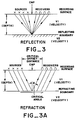
- Figure 3 is a sectional view of the earth illustrating the reflection geometry from a CMP gather of seismic traces.
- Figure 3(a) is a sectional view of the earth illustrating the refraction geometry for a CMP gather of seismic traces.
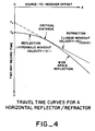
- Figure 4 is a graph that illustrates the corresponding travel times for reflection and refraction event arrivals.
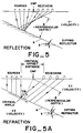
- Figure 5 is a sectional view of the earth illustrating the reflection geometry for a CMP gather where a dip of ⁇ is introduced into the layer boundary.
- Figure 5(a) is a sectional view of the earth illustrating the refraction geometry for a CMP gather where a dip of ⁇ is introduced into the layer boundary.
- Figure 6 is a graph overlay of Figure 2 that illustrates the corresponding travel times for reflection and refraction arrivals for the layer with a dip of ⁇ .
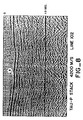
- Figure 7 is a conventional CMP reflection stack for seismic line 102.
- Figure 8 is a corresponding tau-P stack for seismic line 102.
- Figure 9 shows two shot profiles for seismic line 2000.
- Figure 10 is the resulting conventional CMP reflection stack for seismic line 2000.
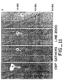
- Figure 11 shows several CMP gathered trace profiles for seismic line 2000.
- Figure 12 shows a constant velocity, tau-P stack for seismic line 2000.
- the CMP stacking method can be used to enhance refraction signals.
- Figure 1 displays a CMP gather of seismic traces on which both reflection events 1 and refraction events 2 are shown.
- hyberbolic moveout is assumed.
- linear moveout must be assumed prior to summing.
- long offset seismic traces will not be muted as in reflection data. Instead, traces which lie inside estimated critical refraction distances (critical offset distances) will be muted.
- the linear moveout applied to the data is directly related to the refractor velocities of interest.
- reflection CMP stacking one can generate a set of constant moveout or velocity stacked panels for an entire seismic line of traverse. These constant refraction velocity panels can be incremented in either even increments of velocity or the reciprocal of velocity commonly called slowness.
- tau-P A commonly used term indicated summing along even increments of slowness is called “tau-P” summing.
- a “tau-P stack” will be defined as a collection of tau-P sums at a single constant refraction velocity for many CMP's along a seismic line of traverse.
- a constant refraction velocity panel is thus a tau-P stack at a single constant linear moveout.
- the linear moveout correction is zero at zero source-to-receiver offset and increases linearly with increasing offset. This makes refraction event arrival times on constant velocity tau-P stack panels equivalent to intercept times commonly used in refraction methods. For simple layered models, intercept times are easily related to refractor subsurface depths. Thus, structural interpretation can be done on tau-P stacks.
- a composite refraction stacked section should be generated using a "cut and splice" method rather than an interpolation across a number of constant velocity tau-P stacks.
- This cut and splice method is illustrated in Figure 2. Shown on the top of the figure are three constant velocity tau-P stack panels. Each of these stacks contains a refraction event of interest 3, each slightly deeper in time than the other.
- a composite tau-P "spliced" section 4 is shown in the bottom of Figure 2. It contains all three refraction events stacked at appropriate linear moveout velocities. Using this method there will be no moveout stretch introduced in either the tau-P stacks or the composite refraction stack.
- Figures 3 and 3a show the reflection and refraction geometry respectively for a CMP gather of seismic traces over a simple two layer velocity (V) model which has V2>V1 such that refraction will take place in layer number 2.
- Figure 4 shows the corresponding travel time curves for the event arrivals.
- the reflection event has hyperbolic moveout at a velocity of V1
- the refraction event has linear moveout at a velocity of V2 beginning at an offset defined by the critical offset distance.
- Both reflection and refraction events are tangent and overlay one another at the critical offset distance.
- the reflection event will persist beyond the critical offset distance as a wide angle reflection. Beyond the critical offset distance this wide angle reflection will undergo phase changes in the event waveform.
- the zero offset two-way reflection time is indicated by T0, while the projected refractor intercept time is indicated by Ti.
- Figures 5 and 5a show the reflection and refraction geometry respectively for a CMP gather of seismic traces over the same two layer model as in Figure 3, except a dip of ⁇ 5 is introduced into the layer boundary 6. Note that if the dip of the layer boundary exceeds the complement of the critical refraction angle, refraction arrivals will not exist.
- the depth to the reflector/refractor (Z) is defined as the perpendicular distance to the layer boundary below the CMP location. Shown in Figure 6 on an overlay of Figure 4 are the corresponding travel times for this dipping layer.
- the zero offset two-way reflection time (T0) will remain unchanged from Figure 4 since the depth, Z, is defined along the perpendicular path to the bed. However, the offset travel time curve for the reflection has changed.
- equation (4) would be a good first order approximation and similar conclusions could be drawn.
- smoothing would result in the intercept times causing smoothing in depth estimates.
- equations (3) nor (4) are correct.
- the time structures would be similar between the two CMP stacked sections.
- refraction arrivals are primarily used in the generation of near surface velocity models for statics computation.
- Common methods use first break picks on refraction events as an input to linear and non-linear model building programs.
- the picks are made either by hand, machine, or both interactively. Once the picks are made, the actual wiggle trace seismic data is discarded and a velocity model is generated which minimizes the difference between raw pick times and theoretical times. There is no error minimization done on the actual wiggle trace seismic data, just the pick times themselves. Without good first breaks on the raw single fold seismic data traces, this type of method tends to give poor results.
- the primary goal in refraction statics is merely to build a near surface velocity model.
- the present invention produces an image of the refractors themselves.
- Conventional CMP reflection stacking is generally useless in imaging the very near surface because recording parameters are mainly designed to image much deeper structures.
- the CMP refraction stacking method disclosed herein is quite suitable for imaging near surface refractors using conventionally recorded CMP reflection data.
- Figure 7 is a conventional CMP reflection stack for seismic line 102. On Figure 7, one sees a set of shallow reflections indicating a depression 7 at about 0.4 seconds. Shown in Figure 8 is the corresponding tau-P stack at a constant velocity of 4200 meters per second. Here a refraction event 8 is seen at about 0.3 seconds intercept time. The structural configuration of this refraction event is very similar to those reflection events on the conventional stack. The reflection boundary and the refraction boundary are therefor likely to be the same event. In this example, both reflection and refraction stacking produce similar images, even though they are derived from independent data on CMP gathered seismic traces; i.e., the reflection data comes from near offsets while the refraction data comes from far offset data. In this example, the refraction image shown in Figure 8 can be used to generate a near surface refraction statics model.
- the CMP reflection method has been unable to produce images of reflectors in the subsurface.
- the primary cause of this has been source generated noise which propagates outward from the energy source.
- this noise has a relatively low propagation velocity, masking only the nearer offset seismic traces. Since refractions are primarily on far offset traces, they may exhibit much less noise contamination and be quite suitable for stacking. This has been the case in several exploration areas. Since conventionally recorded CMP data has limited offsets, only the very shallow refractors can be imaged with the inventive CMP refraction method ( ⁇ 1000 meters). However, by recording longer offsets, deeper refractions can be imaged.
- Figures 9 through 12 each display different forms of seismic data for seismic line number 2000, which is located at an offshore area of poor reflection data quality.
- Figure 9 shows two shot profiles for seismic line 2000.
- the maximum source-to-receiver offset used was about 3800 meters, slightly longer than normal.
- Figure 10 is the resulting conventional CMP reflection stack. Very poor data quality is indicated on this reflection stack.
- Figure 11 illustrates several CMP gathered trace profiles. In both Figures 9 and 11 one can see refraction arrivals 9 on the far offset traces.
- a constant velocity tau-P stack at a velocity of 3043 meters per second is shown in Figure 12.
- a set of refraction events 10 is easily seen at about 0.6 seconds rising to about 0.3 seconds on the left of the section.
- An anticlinal feature 11 is indicated in the center of the section at about 0.6 seconds. None of the events are seen on the conventional stack ( Figure 10).
- structural interpretation is clearly improved by the inventive tau-P refraction stacking method.
Landscapes
- Engineering & Computer Science (AREA)
- Remote Sensing (AREA)
- Physics & Mathematics (AREA)
- Life Sciences & Earth Sciences (AREA)
- Acoustics & Sound (AREA)
- Environmental & Geological Engineering (AREA)
- Geology (AREA)
- General Life Sciences & Earth Sciences (AREA)
- General Physics & Mathematics (AREA)
- Geophysics (AREA)
- Geophysics And Detection Of Objects (AREA)
Claims (6)
- Procédé pour l'amélioration de la résolution sismique de structures géologiques, ledit procédé comprenant les étapes consistant à:(a) positionner des récepteurs d'ondes acoustiques en des positions telles qu' ils se situent à une distance de décalage par rapport à une source d'ondes acoustiques, suffisante pour recevoir les ondes réfractées qui ont pour origine un dispositif de réfraction souterrain intéressant et qui émergent dudit dispositif de réfraction intéressant avec un angle critique;(b) générer des ondes acoustiques dans le sous-sol à partir d'une pluralité de sources d'ondes acoustiques de sorte que lesdites ondes acoustiques rencontrent ledit dispositif de réfraction souterrain intéressant;(c) enregistrer les représentations d'arrivée desdites ondes acoustiques générées par lesdites sources, aux positions desdits récepteurs;
caractérisé par les étapes consistant à(d) collecter les arrivées d'ondes réfractées en des collectes de traces au point milieu commun;(e) rendre silencieuses les représentations arrivantes qui ont pour origine un point situé en-deçà de la distance de décalage critique estimée;(f) effectuer une somme tau-P desdites données d'arrivée de réfraction qui ont pour origine un point situé au-delà de la distance de décalage critique et qui sont projetées avec un décalage source à récepteur de zéro; et(g) afficher les données sommées en tant que superpositions de vitesses constantes. - Procédé selon la revendication 1, dans lequel une pluralité de sources d'ondes acoustiques et de positions de récepteurs d'ondes acoustiques sont utilisées pour générer des sommes tau-P pour une pluralité de points milieux communs.
- Procédé selon la revendication 2, dans lequel une pluralité de vitesses constantes est utilisée, en vue de générer des tableaux multiples de sommes tau-P.
- Procédé selon la revendication 3, dans lequel des parties de plusieurs desdits tableaux multiples sont combinées pour générer une image complète des dispositifs de réfraction souterrains.
- Procédé selon la revendication 4, dans lequel des tableaux multiples de sommes tau-P sont générés en vue de concevoir un modèle des vitesses proches de la surface.
- Procédé selon la revendication 5, dans lequel le modèle des vitesses proches de la surface est généré pour créer une solution à la statique proche de la surface des traces sismiques.
Priority Applications (1)
| Application Number | Priority Date | Filing Date | Title |
|---|---|---|---|
| DE1991608560 DE69108560T2 (de) | 1991-12-20 | 1991-12-20 | Verfahren zur Verbesserung der seismischen Auflösung von geologischen Strukturen. |
Applications Claiming Priority (1)
| Application Number | Priority Date | Filing Date | Title |
|---|---|---|---|
| US07/543,996 US5083297A (en) | 1990-06-26 | 1990-06-26 | Method of improving the seismic resolution of geologic structures |
Publications (2)
| Publication Number | Publication Date |
|---|---|
| EP0548384A1 EP0548384A1 (fr) | 1993-06-30 |
| EP0548384B1 true EP0548384B1 (fr) | 1995-03-29 |
Family
ID=24170374
Family Applications (1)
| Application Number | Title | Priority Date | Filing Date |
|---|---|---|---|
| EP91121892A Revoked EP0548384B1 (fr) | 1990-06-26 | 1991-12-20 | Méthode pour l'amélioration de la résolution sismique de structures géologiques |
Country Status (2)
| Country | Link |
|---|---|
| US (1) | US5083297A (fr) |
| EP (1) | EP0548384B1 (fr) |
Cited By (1)
| Publication number | Priority date | Publication date | Assignee | Title |
|---|---|---|---|---|
| US7230879B2 (en) | 2005-02-12 | 2007-06-12 | Chevron U.S.A. Inc. | Method and apparatus for true relative amplitude correction of seismic data for normal moveout stretch effects |
Families Citing this family (31)
| Publication number | Priority date | Publication date | Assignee | Title |
|---|---|---|---|---|
| FR2717270B1 (fr) * | 1994-03-11 | 1996-04-26 | Elf Aquitaine | Procédé de modélisation de données sismiques cinématiques ayant subi un traitement par au moins un opérateur de déplacement. |
| US5629904A (en) * | 1994-11-30 | 1997-05-13 | Paradigm Geophysical, Ltd. | Migration process using a model based aperture technique |
| FR2739696B1 (fr) * | 1995-10-06 | 1997-11-21 | Elf Aquitaine | Methode de traitement de traces sismiques reflexion enregistrees pour des deports variables |
| US5684754A (en) * | 1995-12-13 | 1997-11-04 | Atlantic Richfield Company | Method and system for correcting seismic traces for normal move-out stretch effects |
| US5761062A (en) * | 1996-02-15 | 1998-06-02 | Western Atlas International, Inc. | Extended offset data processing |
| US5831935A (en) * | 1996-03-05 | 1998-11-03 | Chevron U.S.A. Inc. | Method for geophysical processing and interpretation using seismic trace difference for analysis and display |
| US5724309A (en) * | 1996-03-06 | 1998-03-03 | Chevron U.S.A. Inc. | Method for geophysical processing and interpretation using instantaneous phase and its derivatives and their derivatives |
| RU2126984C1 (ru) * | 1998-07-16 | 1999-02-27 | Глоговский Владимир Маркович | Способ определения глубинно-скоростных параметров среды и построения ее изображения по сейсмическим данным - система prime |
| US6574564B2 (en) | 1998-10-01 | 2003-06-03 | Institut Francais Du Petrole | 3D prestack seismic data migration method |
| FR2784195B1 (fr) * | 1998-10-01 | 2000-11-17 | Inst Francais Du Petrole | Methode pour realiser en 3d avant sommation, une migration de donnees sismiques |
| US6989841B2 (en) * | 2001-05-29 | 2006-01-24 | Fairfield Industries, Inc. | Visualization method for the analysis of prestack and poststack seismic data |
| GB2384068B (en) * | 2002-01-11 | 2005-04-13 | Westerngeco Ltd | A method of and apparatus for processing seismic data |
| FR2838831B1 (fr) * | 2002-04-17 | 2004-08-20 | Inst Francais Du Petrole | Methode pour determiner les corrections statiques primaires a appliquer a des traces sismiques |
| RU2221262C1 (ru) * | 2003-03-14 | 2004-01-10 | Закрытое акционерное общество работников Народное предприятие "Запприкаспийгеофизика" | Способ сейсмической разведки для изучения осадочного чехла при наличии сильно изрезанных акустически жестких границ (варианты) |
| US8326537B2 (en) * | 2004-01-20 | 2012-12-04 | Westerngeco L.L.C. | Survey design using earth observation data |
| US20050157589A1 (en) * | 2004-01-20 | 2005-07-21 | Andreas Laake | Survey design using earth observation data |
| WO2006028501A2 (fr) * | 2004-02-26 | 2006-03-16 | Saudi Arabian Oil Company | Prevision de risques pour des forages a faible profondeur au moyen de donnees de sismique refraction |
| US8243547B2 (en) * | 2006-12-15 | 2012-08-14 | Exxonmobil Upstream Research Co. | Identification and suppression of multiples in ocean bottom seismic data |
| US8467264B2 (en) * | 2008-06-03 | 2013-06-18 | Westerngeco L.L.C. | Acquiring near zero offset survey data |
| CN101625417B (zh) * | 2008-07-08 | 2011-09-07 | 中国石油集团东方地球物理勘探有限责任公司 | 一种优化垂直地震剖面观测系统设计的方法 |
| EP2795366A4 (fr) * | 2011-12-20 | 2016-06-22 | Conocophillips Co | Analyse d'éclairage avec réflexion critique |
| US9158016B2 (en) * | 2012-04-30 | 2015-10-13 | Conocophillips Company | Multi-dimensional data reconstruction constrained by a regularly interpolated model |
| US20140254321A1 (en) * | 2013-03-08 | 2014-09-11 | Chevron U.S.A. Inc. | Methods and systems for determining clathrate presence and saturation using simulated well logs |
| CN103616720B (zh) * | 2013-10-28 | 2016-04-06 | 中国石油天然气集团公司 | 一种折射速度获取方法及装置 |
| WO2017035104A1 (fr) * | 2015-08-24 | 2017-03-02 | Schlumberger Technology Corporation | Correction statique sismique de modèle de vitesse |
| US10067252B2 (en) | 2016-07-25 | 2018-09-04 | Chevron U.S.A. Inc. | Methods and systems for identifying a clathrate deposit |
| RU2670358C1 (ru) * | 2018-01-31 | 2018-10-22 | Керим Акмамедович Хемраев | Способ динамической коррекции отраженных волн с использованием преломленных волн |
| US12105238B2 (en) | 2018-06-20 | 2024-10-01 | Pgs Geophysical As | Long offset acquisition |
| CN112327353B (zh) * | 2019-07-30 | 2024-08-27 | 中国石油天然气集团有限公司 | 一种横波折射层建模方法及装置 |
| US12072461B2 (en) | 2019-10-28 | 2024-08-27 | Pgs Geophysical As | Modified simultaneous long-offset acquisition with improved low frequency performance for full wavefield inversion |
| US12105240B2 (en) | 2019-10-28 | 2024-10-01 | Pgs Geophysical As | Long-offset acquisition with improved low frequency performance for full wavefield inversion |
Family Cites Families (14)
| Publication number | Priority date | Publication date | Assignee | Title |
|---|---|---|---|---|
| US3531763A (en) * | 1965-06-02 | 1970-09-29 | Atlantic Richfield Co | Restricted stacking on shallow reflections |
| US3629798A (en) * | 1969-05-08 | 1971-12-21 | Texas Instruments Inc | Method and system for refraction seismic exploration |
| US4242740A (en) * | 1978-01-09 | 1980-12-30 | Mobil Oil Corporation | Seismic refraction exploration |
| US4241429A (en) * | 1978-03-03 | 1980-12-23 | Mobil Oil Corporation | Velocity determination and stacking process from seismic exploration of three dimensional reflection geometry |
| US4232378A (en) * | 1978-09-20 | 1980-11-04 | Standard Oil Company (Indiana) | Formation absorption seismic method |
| US4393488A (en) * | 1978-10-08 | 1983-07-12 | Chevron Research Company | Exploration system and method of determining elastic parameters and subsurface shape of an earth formation so as to indicate likelihood of the formation being an ore, marker rock, economic mineral or the like |
| US4373197A (en) * | 1978-12-20 | 1983-02-08 | Chevron Research Company | Exploration system for enhancing the likelihood of predicting lithology of earth formations associated with deposits of ore, marker rock and/or economic minerals |
| SU864215A1 (ru) * | 1979-11-01 | 1981-09-15 | Западно-Сибирское отделение Всесоюзного научно-исследовательского института геофизических методов разведки | Способ сейсмической разведки |
| GB2090405A (en) * | 1980-12-31 | 1982-07-07 | Mobil Oil Corp | Determination of static correction from refraction travel time |
| US4476551A (en) * | 1980-12-31 | 1984-10-09 | Mobil Oil Corporation | Selecting offset as a function of time and velocity to stack seismograms with high signal to noise ratio |
| US4577298A (en) * | 1983-09-08 | 1986-03-18 | Mobil Oil Corporation | Method for correcting surface consistent statics in seismic traces |
| US4581724A (en) * | 1983-12-12 | 1986-04-08 | Mobil Oil Corporation | Method for determining source and receiver statics in marine seismic exploration |
| US4802146A (en) * | 1985-05-23 | 1989-01-31 | Mobil Oil Corporation | Method for moveout correction and stacking velocity estimation of offset VSP data |
| US5073876A (en) * | 1990-12-31 | 1991-12-17 | Amoco Corporation | Geophysical exploration using near surface structure corrections developed from common endpoint gather stacked traces |
-
1990
- 1990-06-26 US US07/543,996 patent/US5083297A/en not_active Expired - Fee Related
-
1991
- 1991-12-20 EP EP91121892A patent/EP0548384B1/fr not_active Revoked
Non-Patent Citations (1)
| Title |
|---|
| L. Reimers, H. Rüter, B. Unterstell, CMP-Refraktionsseismik mit Wellengruppenstapelung im tau-P-Bereich in: 11. Mintrop-Seminar "Geophysik zwischen Exploration und Exploitation", Münster, 14.-17. May 1991, p. 101-128 * |
Cited By (1)
| Publication number | Priority date | Publication date | Assignee | Title |
|---|---|---|---|---|
| US7230879B2 (en) | 2005-02-12 | 2007-06-12 | Chevron U.S.A. Inc. | Method and apparatus for true relative amplitude correction of seismic data for normal moveout stretch effects |
Also Published As
| Publication number | Publication date |
|---|---|
| EP0548384A1 (fr) | 1993-06-30 |
| US5083297A (en) | 1992-01-21 |
Similar Documents
| Publication | Publication Date | Title |
|---|---|---|
| EP0548384B1 (fr) | Méthode pour l'amélioration de la résolution sismique de structures géologiques | |
| US7684281B2 (en) | System for combining signals of pressure sensors and particle motion sensors in marine seismic streamers | |
| US4534019A (en) | Common-depth-point method for determining and displaying the shear-velocity reflectivities of a geologic formation | |
| US8239135B2 (en) | Method for calculation of seismic attributes from seismic signals | |
| US6574564B2 (en) | 3D prestack seismic data migration method | |
| US6055482A (en) | Method of seismic signal processing | |
| EP0900393B1 (fr) | Procede pour attenuer les reverberations au moyen d'un cable de fond a pression-vitesse de propagation | |
| US7069150B2 (en) | Method for optimizing migration fields using time slice analysis | |
| US4241429A (en) | Velocity determination and stacking process from seismic exploration of three dimensional reflection geometry | |
| US6188964B1 (en) | Method for using global optimization to the estimation of surface-consistent residual statics | |
| US8811113B2 (en) | Method of summing dual-sensor towed streamer signals using seismic reflection velocities | |
| EP2548052B1 (fr) | Système et procédé d'imagerie vsp de flancs de sel 3d avec des ondes transmises | |
| US20100223012A1 (en) | Method for Determination of Diffractor Locations at Sea Bottom for the Purpose of Attenuating Such Energy | |
| US6584409B2 (en) | Seismic processing method to improve spatial resolution | |
| US6430508B1 (en) | Transfer function method of seismic signal processing and exploration | |
| Farrell et al. | Refraction statics | |
| CA1311830C (fr) | Methode permettant d'augmenter l'efficacite de l'exploration souterraine par le procede vsp | |
| Phinney et al. | Reflection seismic studies of crustal structure in the eastern United States | |
| Pugin et al. | First-arrival alignment static corrections applied to shallow seismic reflection data | |
| EP0113944B1 (fr) | Procede seismique d'exploration a point commun de profondeur | |
| Bakhtiari Rad et al. | Using common-reflection-surface stack for enhanced near-surface seismic reflection imaging: Examples from consolidated and unconsolidated environments | |
| US5532977A (en) | Processing method for obtaining a stack section with zero offsets | |
| Taner et al. | The dynamics of statics | |
| Talagapu | 2d and 3d land seismic data acquisition and seismic data processing | |
| CA2056956A1 (fr) | Methode permettant d'ameliorer la resolution du sondage sismographique des structures geologiques |
Legal Events
| Date | Code | Title | Description |
|---|---|---|---|
| PUAI | Public reference made under article 153(3) epc to a published international application that has entered the european phase |
Free format text: ORIGINAL CODE: 0009012 |
|
| 17P | Request for examination filed |
Effective date: 19930226 |
|
| AK | Designated contracting states |
Kind code of ref document: A1 Designated state(s): DE FR GB IT NL |
|
| 17Q | First examination report despatched |
Effective date: 19940303 |
|
| GRAA | (expected) grant |
Free format text: ORIGINAL CODE: 0009210 |
|
| AK | Designated contracting states |
Kind code of ref document: B1 Designated state(s): DE FR GB IT NL |
|
| RAP2 | Party data changed (patent owner data changed or rights of a patent transferred) |
Owner name: CHEVRON U.S.A. INC. |
|
| REF | Corresponds to: |
Ref document number: 69108560 Country of ref document: DE Date of ref document: 19950504 |
|
| ITF | It: translation for a ep patent filed | ||
| ET | Fr: translation filed | ||
| PLBQ | Unpublished change to opponent data |
Free format text: ORIGINAL CODE: EPIDOS OPPO |
|
| PLBI | Opposition filed |
Free format text: ORIGINAL CODE: 0009260 |
|
| PLBF | Reply of patent proprietor to notice(s) of opposition |
Free format text: ORIGINAL CODE: EPIDOS OBSO |
|
| 26 | Opposition filed |
Opponent name: DMT-GESELLSCHAFT FUER FORSCHUNG UND PRUEFUNG MBH Effective date: 19951227 |
|
| NLR1 | Nl: opposition has been filed with the epo |
Opponent name: DMT-GESELLSCHAFT FUER FORSCHUNG UND PRUEFUNG MBH |
|
| PLBF | Reply of patent proprietor to notice(s) of opposition |
Free format text: ORIGINAL CODE: EPIDOS OBSO |
|
| PLBF | Reply of patent proprietor to notice(s) of opposition |
Free format text: ORIGINAL CODE: EPIDOS OBSO |
|
| PLBF | Reply of patent proprietor to notice(s) of opposition |
Free format text: ORIGINAL CODE: EPIDOS OBSO |
|
| PGFP | Annual fee paid to national office [announced via postgrant information from national office to epo] |
Ref country code: NL Payment date: 19960924 Year of fee payment: 6 |
|
| PGFP | Annual fee paid to national office [announced via postgrant information from national office to epo] |
Ref country code: GB Payment date: 19961108 Year of fee payment: 6 |
|
| PGFP | Annual fee paid to national office [announced via postgrant information from national office to epo] |
Ref country code: FR Payment date: 19961211 Year of fee payment: 6 |
|
| PGFP | Annual fee paid to national office [announced via postgrant information from national office to epo] |
Ref country code: DE Payment date: 19961227 Year of fee payment: 6 |
|
| PG25 | Lapsed in a contracting state [announced via postgrant information from national office to epo] |
Ref country code: GB Free format text: LAPSE BECAUSE OF NON-PAYMENT OF DUE FEES Effective date: 19971220 |
|
| PLAW | Interlocutory decision in opposition |
Free format text: ORIGINAL CODE: EPIDOS IDOP |
|
| PLAW | Interlocutory decision in opposition |
Free format text: ORIGINAL CODE: EPIDOS IDOP |
|
| PG25 | Lapsed in a contracting state [announced via postgrant information from national office to epo] |
Ref country code: NL Free format text: LAPSE BECAUSE OF NON-PAYMENT OF DUE FEES Effective date: 19980701 |
|
| GBPC | Gb: european patent ceased through non-payment of renewal fee |
Effective date: 19971220 |
|
| NLV4 | Nl: lapsed or anulled due to non-payment of the annual fee |
Effective date: 19980701 |
|
| PG25 | Lapsed in a contracting state [announced via postgrant information from national office to epo] |
Ref country code: DE Free format text: LAPSE BECAUSE OF NON-PAYMENT OF DUE FEES Effective date: 19980901 |
|
| REG | Reference to a national code |
Ref country code: FR Ref legal event code: ST |
|
| RDAH | Patent revoked |
Free format text: ORIGINAL CODE: EPIDOS REVO |
|
| RDAH | Patent revoked |
Free format text: ORIGINAL CODE: EPIDOS REVO |
|
| RDAG | Patent revoked |
Free format text: ORIGINAL CODE: 0009271 |
|
| STAA | Information on the status of an ep patent application or granted ep patent |
Free format text: STATUS: PATENT REVOKED |
|
| 27W | Patent revoked |
Effective date: 19990207 |
|
| PG25 | Lapsed in a contracting state [announced via postgrant information from national office to epo] |
Ref country code: FR Free format text: LAPSE BECAUSE OF NON-PAYMENT OF DUE FEES Effective date: 19971231 |