EP0548389A1 - Contrôle de la température d'eau chaude pour une installation de chauffage - Google Patents
Contrôle de la température d'eau chaude pour une installation de chauffage Download PDFInfo
- Publication number
- EP0548389A1 EP0548389A1 EP91122021A EP91122021A EP0548389A1 EP 0548389 A1 EP0548389 A1 EP 0548389A1 EP 91122021 A EP91122021 A EP 91122021A EP 91122021 A EP91122021 A EP 91122021A EP 0548389 A1 EP0548389 A1 EP 0548389A1
- Authority
- EP
- European Patent Office
- Prior art keywords
- water
- valve
- supply
- water flow
- heating system
- Prior art date
- Legal status (The legal status is an assumption and is not a legal conclusion. Google has not performed a legal analysis and makes no representation as to the accuracy of the status listed.)
- Granted
Links
- 239000008236 heating water Substances 0.000 title 1
- XLYOFNOQVPJJNP-UHFFFAOYSA-N water Substances O XLYOFNOQVPJJNP-UHFFFAOYSA-N 0.000 claims abstract description 164
- 238000010438 heat treatment Methods 0.000 claims abstract description 163
- 239000008400 supply water Substances 0.000 claims abstract description 137
- 238000002156 mixing Methods 0.000 claims description 31
- 239000000428 dust Substances 0.000 claims description 14
- 125000006850 spacer group Chemical group 0.000 claims description 4
- 238000002485 combustion reaction Methods 0.000 claims 2
- 239000000203 mixture Substances 0.000 claims 1
- 210000004907 gland Anatomy 0.000 description 16
- 238000010586 diagram Methods 0.000 description 13
- 239000012530 fluid Substances 0.000 description 12
- 239000004033 plastic Substances 0.000 description 8
- 229920003023 plastic Polymers 0.000 description 8
- 238000002955 isolation Methods 0.000 description 7
- 230000007246 mechanism Effects 0.000 description 5
- UGFAIRIUMAVXCW-UHFFFAOYSA-N Carbon monoxide Chemical compound [O+]#[C-] UGFAIRIUMAVXCW-UHFFFAOYSA-N 0.000 description 4
- 230000006978 adaptation Effects 0.000 description 4
- 239000003546 flue gas Substances 0.000 description 4
- 239000000463 material Substances 0.000 description 4
- 238000000034 method Methods 0.000 description 4
- 238000005496 tempering Methods 0.000 description 4
- 238000009833 condensation Methods 0.000 description 3
- 230000005494 condensation Effects 0.000 description 3
- 230000007423 decrease Effects 0.000 description 3
- 230000003247 decreasing effect Effects 0.000 description 3
- 230000000694 effects Effects 0.000 description 3
- 238000009434 installation Methods 0.000 description 3
- 230000005855 radiation Effects 0.000 description 3
- RYGMFSIKBFXOCR-UHFFFAOYSA-N Copper Chemical compound [Cu] RYGMFSIKBFXOCR-UHFFFAOYSA-N 0.000 description 2
- 238000007792 addition Methods 0.000 description 2
- XAGFODPZIPBFFR-UHFFFAOYSA-N aluminium Chemical compound [Al] XAGFODPZIPBFFR-UHFFFAOYSA-N 0.000 description 2
- 229910052782 aluminium Inorganic materials 0.000 description 2
- QVGXLLKOCUKJST-UHFFFAOYSA-N atomic oxygen Chemical compound [O] QVGXLLKOCUKJST-UHFFFAOYSA-N 0.000 description 2
- 230000004888 barrier function Effects 0.000 description 2
- 239000004020 conductor Substances 0.000 description 2
- 229910052802 copper Inorganic materials 0.000 description 2
- 239000010949 copper Substances 0.000 description 2
- 229920003020 cross-linked polyethylene Polymers 0.000 description 2
- 239000004703 cross-linked polyethylene Substances 0.000 description 2
- 230000006866 deterioration Effects 0.000 description 2
- 239000000446 fuel Substances 0.000 description 2
- 238000012423 maintenance Methods 0.000 description 2
- 239000003550 marker Substances 0.000 description 2
- 239000001301 oxygen Substances 0.000 description 2
- 229910052760 oxygen Inorganic materials 0.000 description 2
- 238000010926 purge Methods 0.000 description 2
- 230000004044 response Effects 0.000 description 2
- 230000020347 spindle assembly Effects 0.000 description 2
- 238000005406 washing Methods 0.000 description 2
- 239000004698 Polyethylene Substances 0.000 description 1
- 230000009471 action Effects 0.000 description 1
- 230000000712 assembly Effects 0.000 description 1
- 238000000429 assembly Methods 0.000 description 1
- 238000011217 control strategy Methods 0.000 description 1
- 238000001816 cooling Methods 0.000 description 1
- 238000007865 diluting Methods 0.000 description 1
- 239000002803 fossil fuel Substances 0.000 description 1
- 238000011065 in-situ storage Methods 0.000 description 1
- 230000007774 longterm Effects 0.000 description 1
- -1 polyethylene Polymers 0.000 description 1
- 229920000573 polyethylene Polymers 0.000 description 1
- 230000008569 process Effects 0.000 description 1
- 230000002441 reversible effect Effects 0.000 description 1
- 238000007789 sealing Methods 0.000 description 1
Images




Classifications
-
- F—MECHANICAL ENGINEERING; LIGHTING; HEATING; WEAPONS; BLASTING
- F24—HEATING; RANGES; VENTILATING
- F24D—DOMESTIC- OR SPACE-HEATING SYSTEMS, e.g. CENTRAL HEATING SYSTEMS; DOMESTIC HOT-WATER SUPPLY SYSTEMS; ELEMENTS OR COMPONENTS THEREFOR
- F24D19/00—Details
- F24D19/10—Arrangement or mounting of control or safety devices
- F24D19/1006—Arrangement or mounting of control or safety devices for water heating systems
- F24D19/1009—Arrangement or mounting of control or safety devices for water heating systems for central heating
- F24D19/1015—Arrangement or mounting of control or safety devices for water heating systems for central heating using a valve or valves
- F24D19/1024—Arrangement or mounting of control or safety devices for water heating systems for central heating using a valve or valves a multiple way valve
- F24D19/1033—Arrangement or mounting of control or safety devices for water heating systems for central heating using a valve or valves a multiple way valve motor operated
-
- F—MECHANICAL ENGINEERING; LIGHTING; HEATING; WEAPONS; BLASTING
- F24—HEATING; RANGES; VENTILATING
- F24D—DOMESTIC- OR SPACE-HEATING SYSTEMS, e.g. CENTRAL HEATING SYSTEMS; DOMESTIC HOT-WATER SUPPLY SYSTEMS; ELEMENTS OR COMPONENTS THEREFOR
- F24D3/00—Hot-water central heating systems
- F24D3/08—Hot-water central heating systems in combination with systems for domestic hot-water supply
-
- F—MECHANICAL ENGINEERING; LIGHTING; HEATING; WEAPONS; BLASTING
- F24—HEATING; RANGES; VENTILATING
- F24D—DOMESTIC- OR SPACE-HEATING SYSTEMS, e.g. CENTRAL HEATING SYSTEMS; DOMESTIC HOT-WATER SUPPLY SYSTEMS; ELEMENTS OR COMPONENTS THEREFOR
- F24D3/00—Hot-water central heating systems
- F24D3/12—Tube and panel arrangements for ceiling, wall, or underfloor heating
-
- G—PHYSICS
- G05—CONTROLLING; REGULATING
- G05D—SYSTEMS FOR CONTROLLING OR REGULATING NON-ELECTRIC VARIABLES
- G05D23/00—Control of temperature
- G05D23/01—Control of temperature without auxiliary power
- G05D23/13—Control of temperature without auxiliary power by varying the mixing ratio of two fluids having different temperatures
- G05D23/1306—Control of temperature without auxiliary power by varying the mixing ratio of two fluids having different temperatures for liquids
- G05D23/132—Control of temperature without auxiliary power by varying the mixing ratio of two fluids having different temperatures for liquids with temperature sensing element
-
- Y—GENERAL TAGGING OF NEW TECHNOLOGICAL DEVELOPMENTS; GENERAL TAGGING OF CROSS-SECTIONAL TECHNOLOGIES SPANNING OVER SEVERAL SECTIONS OF THE IPC; TECHNICAL SUBJECTS COVERED BY FORMER USPC CROSS-REFERENCE ART COLLECTIONS [XRACs] AND DIGESTS
- Y02—TECHNOLOGIES OR APPLICATIONS FOR MITIGATION OR ADAPTATION AGAINST CLIMATE CHANGE
- Y02B—CLIMATE CHANGE MITIGATION TECHNOLOGIES RELATED TO BUILDINGS, e.g. HOUSING, HOUSE APPLIANCES OR RELATED END-USER APPLICATIONS
- Y02B30/00—Energy efficient heating, ventilation or air conditioning [HVAC]
Definitions
- the invention described herein relates to hydronic heating systems for dwellings, offices, etc. and more particularly to such a system adapted and operated to feed some of the system return water flow to the system boiler supply water flow so as to maintain the temperature of the supply water flow to the system heating loops within a predetermined range.
- Hydronic heating systems for heating the rooms in a dwelling, office, etc, are used widely in Europe and to a lesser extent in the United States.
- Water heated in a boiler is distributed to heating loops of tubing in the dwelling that carry the heat by radiation, conduction and convection to the rooms in the dwelling.
- a common technique provides a boiler hot water supply feeding the supply header of the heating loops and the boiler water return to which the return header of the heating loops connects. The return water is heated in the boiler and sent out again as hot supply water, and so the water is cycled through the essentially closed system.
- One or more water pumps in this system keep the water flowing and valves control water flow rates through the loops depending on demand.
- a heating loop may include several heating elements like wall mounted radiators and/or baseboard finned tubing that are the principal heat exchangers of the loop, or the tubing itself may be the principal heat exchanger of the loop.
- the tubing is usually buried in the floor of a room and the tubing heats the floor.
- the tubing is buried in a special concrete and so heat exchange is principally by conduction and radiation to the concrete, which in turn heats the room by some conduction and convection, but principally by radiation.
- this type of heating is called Radiant Floor Heating (RFH).
- RWH Radiant Wall Heating
- RWH Radiant Wall Heating
- the supply water temperature from the boiler must be controlled so that it does not exceed certain limits that are substantially lower than the usual boiler supply water temperature.
- the temperature of radiator elements on the wall must not be so high that they are not safe to touch; second, for RFH and RWH the temperature of the floor or the wall must not be uncomfortable hot; and third, where the tubing is plastic, the water temperature for some plastic materials must not exceed about 140°F.
- Good quality "cross-linked" polyethylene tubing on the other hand, can carry water at temperature in excess of 140°F without any deterioration of the tubing or the tubing oxygen barrier.
- the heating loop supply water temperature could be maintained low and so avoid these problems by simply operating the boiler at a lower water temperature.
- that can cause flue gas condensation on the boiler water heat exchanger.
- the flue gas due point can be as high as 140°F and so to avoid flue gas condensation it is preferred that the boiler supply water temperature be not less than 140°F
- the boiler water supply temperature is usually well above 140°F and often at about 190°F to 200°F, and so the boiler supply temperature must be stepped down before it is fed to the heating loops.
- a three-way, electrically controlled, motorized mixing valve has been used in the boiler supply line that feeds the supply header for the heating loops, between the boiler supply and the heating loops supply header. This mixing valve has two inputs and one output. One input is directly from the boiler hot water supply, the other input is from the return header of the heating loops and the output is directly to the supply header of the heating loops.
- the mixing valve motor is electrically energized by remote reset controls that sometimes respond to outside ambient temperature, inside room temperature, boiler water temperature, supply header water temperature, etc. In operation, the mixing valve mixes some return water with the hot supply water to reduce the temperature of the supply water that is fed to the supply header of the heating loops.
- remote reset controls that sometimes respond to outside ambient temperature, inside room temperature, boiler water temperature, supply header water temperature, etc.
- the mixing valve mixes some return water with the hot supply water to reduce the temperature of the supply water that is fed to the supply header of the heating loops.
- non-motorized mixing valves have been used in the boiler supply line. These have the disadvantage of providing less comfort and lower long term fuel economy.
- these systems are sometimes used. They usually have a remote electrically operated room thermostat controlling a circulator wired through a surface aquastat to prevent overheated water from entering the heating loops; and on the boiler supply line is a dial thermometer that indicates the supply water temperature into the loop supply header.
- manually setting the water temperature into the heating loops by adjusting the valve setting is not precise.
- a thermostat is defined as a device for controlling a heating or cooling system that responds to temperature by expanding and contracting and has an actuator.
- any thermostat the part that expands and contracts
- the rest of it may be mechanical and/or electrical or totally electrical.
- an electric thermostat uses electric power to energize the thermostat actuator, whereas a non-electric thermostat does not use electric energy to energize the actuator.
- a three-way modulated diverting or by-pass valve is provided in the return line to the boiler between the heating loop return header and the boiler return.
- the diverting valve has one input and two outputs. The input is from the heating loops return header; the first output is to the boiler return line; and the second output is to the boiler supply line.
- the diverting valve diverts some of the cooler return water to the hot supply water to reduce the temperature of the supply water feeding the heating loop supply header.
- the supply water is diluted with return water, lowering the temperature of the supply water directly from the boiler.
- the diverting valve is a modulated valve and the temperature of the supply water flowing to the supply header may be detected and used as a feedback control signal to modulate the valve.
- system water pump is in the return line between the return header and the diverting valve input and so that input is at the high pressure side of the pump.
- the three-way diverting valve in the return line with its control including temperature feedback from the heating loops supply header provides automatic water tempering, insuring constant supply water temperature to the heating loops. It may be relatively inexpensive and reliable and can be the primary entry-level controller in a hydronic heating system in a dwelling, office, etc.. High quality three-way modulated diverting valves are available from a number of sources.
- the feedback control (set point control) of the diverting valve can be provided by remote electric transducers and an electric control head having a motor or solenoid driving (modulating) the diverting valve.
- Feedback control can also be provided by a non-electric thermostat control head on the valve, controlled by a capillary temperature sensor. In both cases, the feedback control derived from the temperature of the diluted (tempered) supply water that is fed to the heating loops header is the primary valve modulation control.
- the feedback control is entirely mechanical.
- the bulb of the capillary sensor can be inserted directly into the diluted supply water line or into the heating loops supply header, or it may be clamped to the supply line next to the supply header in intimate thermal contact therewith, so that it is at the temperature of the diluted supply water flowing into the supply header.
- capillary fluid in the bulb expands with temperature applying a pressure force through the capillary to the actuator head and so the diverting valve is modulated to increase or decrease the flow of return water to the supply header as necessary to maintain the water temperature at a predetermined value.
- That predetermined value can be set by a mechanical bias setting on the control head. This set point control configuration insures that an accurate reading of the supply header water temperature is made continuously; and simultaneously, any deviation from the setting is immediately nulled by modulating the valve
- a three-way modulated mixing valve is provided at the input to the heating loops supply header, with supply water temperature feedback control modulating the valve.
- the mixing valve is controlled and modulated by a non-electric thermostat control head attached to the mixing valve and controlled by a capillary temperature sensor.
- the mixing valve is modulated by non-electric feedback of the diluted supply water temperature.
- the bulb of the capillary sensor may be inserted into the diluted supply water or it may be clamped to the supply line next to the supply header so that it is at the temperature of water in the supply header.
- Capillary fluid in the bulb expands with temperature applying a pressure force through the capillary to the control head actuator and so the valve is modulated to increase or decrease the flow of return water through the mixing valve as necessary to maintain the temperature of the supply water to the supply header at or below a predetermined value. That value can be set by a mechanical setting on the control head. This set point control configuration insures that an accurate reading of the supply header water temperature is made continuously; and, simultaneously, any deviation from the setting is immediately nulled by modulating the mixing valve.
- the three-way diverting valve used as described above with an electric or a non-electric control head has one input and two outputs; the through output is to the return line to the boiler; the diverted output is to the boiler supply line; it has a spring loaded valve stem that carries two plugs, one to close the through output and the other to close the diverted output; and a spring that urges the stem to move in the direction that closes the diverted output and opens the through output.
- the control head piston engages the valve stem only to push the stem in and so increase diverted water flow when the thermostat control head setting calls for less heat or a lower temperature of the heating loop header water temperature. If the head is set too high, or does not work, or is removed from the valve, the diverted output of the valve closes and the supply water to the heating loops is not diluted and may be too hot for comfort of cause other undesirable effects described herein.
- any type of electric or non-electric (totally mechanical) control head attached to the diverting valve as described herein is such that the control head piston engages the valve stem only to push the stem in and so increase diverted water flow when the control head setting (set electrically or mechanically) calls for less heat or a lower temperature of supply water to the supply header than the actual temperature of supply water to the supply header (actual heat).
- the actual temperature of supply water to the supply header is referred to herein as the control water temperature and if that temperature is below what the head setting calls for, the head piston does not engage the valve stem at all and so the valve spring moves the stem to close the diverted output and open the through output.
- this valve control actuation produces: maximum flow of diverted return water to the supply line when the control water temperature is substantially greater than the control head setting; a variable modulated flow of diverted return water to the supply line when the control water temperature and the control head setting are about the same (equivalent); and zero diverted water flow when the control water temperature is substantially less than the control head setting.
- the header for the heating loops is fed undiluted boiler supply water, which is often too hot for efficient delivery of heat and too hot for comfort.
- valve spring also completely closes the diverted water output and the header for the heating loops is fed undiluted boiler supply water making: radiator elements on the wall too hot to touch; RFH floor and RWH wall temperatures uncomfortable hot; and in heating loops using plastic tubing, the water temperature would be in excess of the recommended temperature and could cause deterioration of the tubing or the tubing oxygen barrier.
- a diverting valve is changed or adapted by installing a mechanism in the valve that insures that the diverted output of the valve cannot be less than a determinable part of the total flow through the valve. Having determined that minimum part and set the installed mechanism accordingly, the supply water temperature in the header feeding the heating loops is limited and so will not be too hot for efficient delivery of heat or too hot for comfort, regardless of the action of the control head, or even if the control head is removed from the valve. In other words, this mechanism insures that the temperature of the water flowing to the header for the heating loops is always less than the boiler supply water temperature.
- the present invention provides means for limiting the temperature of the supply water of a hydronic heating system where the water is heated in a boiler powered by burning a fuel.
- the reasons for limiting the temperature are several and depend upon the kind of tubing and/or heat exchanger elements that are used in the system heating loops. As mentioned above, some elements are exposed to the occupants of the dwelling and so they must not be so hot that they are not safe to touch. Where RFH or RWH is used, the floor or wall temperature must not be uncomfortable hot, and where plastic tubing is used the water temperature must be limited so as not to cause early failure of the tubing. Hence, the temperature of the supply water fed to the heating loops is controlled in view of the kind of materials used and in view of the kind of elements used in the heating loops. In a given installation, there may be more than one different kind of element and more than one different kind of material used in the heating loops, all fed from the same boiler. For this reason the improvements of the present invention enable ready, reliable, in situs adjustment to insure that supply water temperature does not exceed the limitations of the elements and/or comfort.
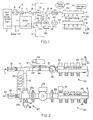
- Figure 2 is a schematic diagram of a typical hydronic heating system installed in a dwelling incorporating the first of the present inventions and Figure 1 is a detailed elevation view of the distribution station of the hydronic system.
- the system includes a boiler 1 that supplies the hydronic distribution station 3 and also supplies the dwelling domestic hot water (DHW) tank 2.
- DHW dwelling domestic hot water
- the usual requirement of the system is to provide DHW water as hot as 180°F, which can be required for washing machines and dish washers.
- the same boiler supply also feeds the hydronic heating system 3.
- the hydronic heating system distribution station 3 includes four heating loops 20, of which one or more require that the supply water temperature be substantially lower than 180°F and so for those loops, return water is diverted to the loop supply, diluting the loop supply and so reducing the temperature (tempering) the loop supply water to within the required limits.
- FIG. 1 shows details of the distribution station 3 incorporating a three-way modulated diverting valve in the return line.
- the boiler supply line 11 to the station includes a unidirectional check valve 12, an isolation ball valve 13, a Tee connection 14 to diverting line 15 and the continuation 16 of supply line 11 to heating loop supply header 17 that feeds the several (four) heating loops 20.
- a separate loop tubing connection to the supply header 17 is provided for each loop.
- At the other end of each loop a similar tubing connection is provided to the return header 18.
- the return line from header 18 to the boiler return reservoir 21 includes a first section 22 to water pump 23, three-way modulated diverting valve 24, boiler return line 25 and isolation ball valve 26 in the return line.
- Three-way modulated diverting valve 24 has one water flow input 24a from pump 23, receiving return water from the heating loops, a first water flow output 24b to the boiler return line 25 and a second water flow output 24c to diverting line 15 that connects to the supply line Tee connection 14.
- a suitable structure of diverting valve 24 is shown in Figure 6.
- the valve includes a housing 27 defining the input and two outputs, a diverting flow seat 28 and a return flow seat 29.
- the valve spindle assembly 30 includes the stem 31, carrying the diverting flow disc 32 and the return flow disc 33 adapted to close against the seats 28 and 29, respectively.
- the stem is carried by the stem gland assembly 34 that fits tightly to the housing and is sealed thereto, the stem being slideably carried by the gland assembly and the stem is spring loaded by coil spring 35 which urges the stem to move in a direction that closes the diverting water passage 24c and opens the return water passage 24b.
- Modulation of valve 24 is accomplished by moving the stem 31 against spring 35 and is done by delivering a force to the stem to overcome the spring resistance.
- a non-electric structure for delivering this modulating force to the valve stem is also shown in Figures 2 and 6. It is a non-electric, thermostatic, automatic controller for the valve including an actuating control head 36 , a thermal sensor bulb 37 and a capillary line 38 from the sensor bulb to the head.
- the sensor bulb and capillary contain a fluid that expands as the fluid temperature increases, delivering an increased pressure force via the capillary to the head, which converts the fluid pressure to a mechanical force against the stem at the end 75 thereof.
- the temperature of the diluted supply water flowing to the loops supply header 17 is effective as a non-electric feedback control signal to modulate the valve.
- FIG. 10 is a schematic diagram of the same hydronic heating system as shown in Figure 1 and in which the valve 24 control head 40 contains an electric actuator that is energized by an electric signal from electric control switch circuit 41. This is described more fully hereinbelow.
- Sensor bulb 37 is preferably located so as to detect the temperature of the supply water flow into header 17 that feeds the heating loops. This can be done using a structure (not shown) for inserting the bulb into the supply water line 16 or inserting the bulb into the supply header 17. It can also be done more simply by attaching the sensor bulb in intimate thermal contact with the outside of supply line 16 as shown in Figure 2.
- the elongated sensor bulb 37 is oriented longitudinally along line 16, partially enclosed by mounting block 44 that also partially encloses line 16 and is secured tightly thereto by strap 45.
- Block is made of highly thermally conductive material such as copper or aluminum, to insure that the temperature of the fluid in the bulb is substantially the same as the temperature of the tempered supply water flowing in line 16 immediately adjacent thereto.
- this assembly may be covered with an insulating sleeve 46 to insure the equality of temperature.
- a visible temperature gauge 43 is also attached to line 16 close to header 17 in intimate thermal contact with the line so that it displays a temperature as near to the temperature of the tempered supply water as possible.
- An initial adjustment of the system when operation first commences can be carried out as follows: (a) with supply water flowing to one or more of the heating loops, observe the temperature indication of temperature gauge 43; (b) if the temperature indicated by the gauge is too high, rotate manual adjusting ring 39 of controller head 36, decreasing the index number in line with the marker thereon, thereby increasing the force that the head exerts on the valve stem spring for the then prevailing bulb fluid pressure and so diverted return water flow via line 15 to supply line 16 is increased reducing the temperature of the water in the header; (c) on the other hand, if the temperature gauge 43 reads too low, rotate ring 39 to increase the indicated number and so less return water is diverted to the supply line and the temperature of the supply water flow to header 17 increases.
- the supply header 17 may be equipped with an air vent 47 and the return header may be equipped with a purge line 48 controlled by a manually operated valve 49.
- Supply water flow to each of heating loops may be controlled by a balancing valve with an internal position set screw.
- Such balancing valves for each loop are denoted 50.
- An alternate control for each loop could be an electrically operated power head like 51, each controlled by an electrical thermostat in the dwelling.
- Figure 3 shows the same system as Figure 1 with an additional distribution station 61 in series with distribution station 3, providing supply and return headers for additional heating loops 60 and includes supply and return headers 67 and 68 that each may be equipped the same as headers 17 and 18, respectively.
- the supply water at controlled temperature is fed to both of the supply headers 17 and 67, first into header 17 and then through isolation valve 69 into header 67 and so heating loops 20 and heating loops 60 are fed tempered supply water from the same control.
- return water from heating loops 60 flows through valve 70 to return header 18 where it is combined with return water from loops 20 and on through pump 23 and diverting valve 24 to boiler return 21.
- This system is suitable where all of the heating loops 20 and 60 require supply water at the same temperature.
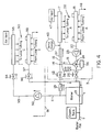
- the system in Figure 4 also includes two distribution stations.
- Station 3 is the same as Station 3 in Figures 1 and 3 and supply water is tempered so that it does not exceed predetermined limits.
- the other station 91 does not include any tempering of supply water, but receives supply water directly from the boiler supply line 11 via pump 92 and supply line 93 of station 91.
- a supply line isolation valve 94 is provided in the line into supply header 95 and a return line isolation valve 96 is provided in the return line 97 from return header 98.
- the heating loops 90 extend between supply and return headers 95 and 98.
- the two distribution systems 3 and 91 receive boiler supply water at the temperature required for station 91 and the heating loops on that station are designed for operation at that temperature which may be 180°F or higher.
- heating loops 20 require lower supply water temperature and so are equipped with the system that diverts return water into the supply header to maintain the lower supply water temperature.
- This system may or may not feed a DHW tank and so the boiler high water temperature may be limited by the limitations of heating loops 90.
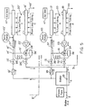
- Figure 5 illustrates a system having two distribution stations each of which requires supply water temperature control, and the supply water temperature required for each station is different.
- the first distribution station 3 and the second distribution station 3' are essentially connected in parallel with the boiler supply and return and they are substantially identically equipped, although they are operated at different temperatures. Since the equipment at each of these stations is the same, they bear the same reference numbers, but in station 3' the reference numbers all include a prime.
- the boiler may or may not supply hot water to other systems in the premises.
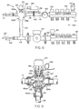
- Figure 7 is a schematic diagram of a typical hydronic heating system installed in a dwelling incorporating the second of the present inventions and Figure 8 is a detailed elevation view of the distribution station of the hydronic system.
- the boiler 101 supplies the system distribution station 103 and the domestic hot water (DHW) tank 102.
- DHW domestic hot water
- the boiler provides DHW water at about 180°F, as required for washing machines and dish washers and the boiler supply also feeds the hydronic heating system.
- the hydronic heating system includes four heating loops 120 between supply header 117 and return header 118, of which one or more require that the supply water temperature be substantially lower than 180°F and so for those loops, return water is diverted to the loop supply, tempering the loop supply and so reducing the temperature of the loop supply water to within the required limits.
- FIG. 8 shows details of the distribution station 103 incorporating a three-way modulated mixing valve 124 in the boiler supply line 111.
- the boiler supply line also includes a unidirectional check valve 112, isolation ball valve 113 and the continuation 116 of supply line 111 to heating loop supply header 117 that feeds the several (four) heating loops 120, a separate loop tubing connection to the supply header being provided for each loop. At the other end of each loop a similar tubing connection is provided to the return header 118.
- the return line from header 118 to the boiler return reservoir 121 includes a first section 122 to water pump 123, a Tee connector 114 to the three-way modulated mixing valve 124, boiler return line 125 and isolation ball valve 126 in the return line.
- Three-way mixing valve 124 has a first water flow input 124a from supply line 111, a second water flow input 124b from shunt line 115 that feeds return water to the valve from the Tee connector 114 and one output to the supply header 117.
- a suitable structure of mixing valve 124 is shown in Figure 9.
- the valve includes a housing 127 defining the two inputs and the output, a supply water flow seat 128 and a return water flow seat 129.
- the valve spindle assembly 130 includes the stem 131, carrying the supply flow plug 132 and the return flow plug 133 adapted to close against the supply and return flow seats 128 and 129, respectively.
- the stem is carried by the stem spring guide assembly 134 at one end, and the shunt input guide assembly 135 at the other end, the stem being slideably carried by these assemblies.
- the stem is spring loaded by coil spring 136 which urges the stem to move in a direction that closes the supply water input passage 124a and opens the return water input passage 124b.
- the spring force tends to position the valve to reduce the temperature of the mixed water flowing from the valve output 124c to the heating loops supply header.
- Valve 124 is modulated by moving the stem 131 against spring 136 by delivering a force to the stem to overcome the spring resistance.
- a structure for delivering this modulating force to the valve stem is also shown in Figures 8 and 9.
- It is a non-electric, thermostatic automatic controller for the valve including an actuating control head 137 , a thermal sensor bulb 138 and a capillary line 139 from the sensor bulb to the head.
- the sensor bulb and capillary contain a fluid that expands as the fluid temperature increases delivering an increased pressure force via the capillary to the head.
- the pressure from the capillary opposes a spring (not shown) that exerts a force against the end 140 of the mixing valve stem 131 (see Figure 9).
- the force on the mixing valve stem decreases and the valve stem spring 136 moves the valve to increase the shunted water flow from the return line that is mixed with supply water flow to the supply header.
- Sensor bulb 138 is located on the supply line adjacent supply header 117 to detect the temperature of the water flow into the supply header.
- the elongated sensor bulb is attached longitudinally along line 116, partially enclosed by mounting block 141 that also partially encloses line 116 and is secured tightly thereto by strap 142.
- Block is made of highly thermally conductive material such as copper or aluminum and is covered with an insulating sleeve 144 to insure the equality of temperature.
- a visible temperature gauge 143 is also attached to line 116 close to header 117 in intimate thermal contact with the line so that it displays a temperature as near to the supply water temperature as possible.
- An initial adjustment of the system when operation first commences can be carried out as follows: (a) with supply water flowing to one or more of the heating loops, observe the temperature indication of temperature gauge 143; (b) if the temperature indicated by the gauge is too high, rotate manual adjusting ring 145 of controller head 137 decreasing the index number that is in line with the marker thereof, thereby decreasing the force that the head exerts on the dial stem spring for the then prevailing bulb fluid pressure and so return water flow via shunt 115 to supply line 116 is increased, reducing the temperature of the water in the header; (c) on the other hand, if the temperature gauge 143 reads too low, rotate ring 145 to increase the indicated number and less return water is mixed with supply water and so the temperature of the mixed (diluted) supply water flow to header 117 increases.
- the supply header 117 may be equipped with an air vent 147 and the return header may be equipped with a purge line 148 controlled by a manually operated valve 149.
- Supply water flow to each of heating loops may be controlled by a balancing valve with an internal position set screw.
- Such balancing valves for each loop are denoted 150.
- An alternate control for each loop could be an electrically operated power head like 151 each controlled by an electrical thermostat in the dwelling.
- Figures 1 and 10 are schematic diagrams of a typical hydronic heating system installed in a dwelling having a diverting valve in the system return water line, that may incorporate a high temperature limit stop in the valve.
- Control head 36 in Figure 1 with bulb 137 and capillary 138 is a non-electric thermostat control system for diverting valve 24.
- the control head 40 is electric and the thermostatic control system includes an elecric motor or actuator in the head that is energized by 24 VAC from head control switch circuit 41.
- One of the electric signal inputs to switch circuits 41 is from temperature sensor 42 that is attached to supply line 16 and so the temperature detected by the sensor is essentially the temperature of the diluted supply water flowing into the supply header 17.
- Diverting valve 24, as shown in Figures 6 and 14, has a gland assembly 34 that includes the gland housing 56 that screws into the valve housing 27 by threads 57 and the two housings are sealed against water pressure by O ring seal 58.
- the stem is slideably held by the gland assembly and sealed thereto by water tight seal 59 held in place by retainer ring 61.
- Spring 35 is held in housing 56 in space 63 and at one end bears against retainer ring 61 fixed to the housing and at the other end bears against the stem ring 64, which is fixed to the stem.
- the external open end of the gland housing is closed by hex head dust plug 65 that screws into the open end of the housing by threads 66 and may carry an O ring 67 sealing against the housing.
- hex head dust plug 65 screws tight to the gland housing and serves no other purpose than to slideably pass the stem to outside the valve and close the inside of the housing containing the spring against outside moisture and dirt. There is no water pressure in the space 63 inside the gland housing.
- threads 68 for attaching the electric control head 40 or the non-electric thermostatic control head 36.
- either control head is attached by head holding nut 72 by screwing the nut onto threads 68.
- the nut is captured by the control head positioning boss 73 that abuts the gland housing when nut 72 is tightened to fix the position of the control head piston 74 relative to the end 75 of the stem that projects from plug 65 and the piston is guided by sleeve 76 centrally located in the boss 73.
- Electric control head 40 shown in Figure 10, contains an electric motor or an electric actuator that is controlled energized by 24 VAC electric power from control switch circuit 41. It has a piston that drives into and out of the diverting valve 24 against the valve stem 31 and so positions (opens and closes) the valve. Suitable electric control heads for controlling such a three-way diverting valve are available in the market place.
- the electric head may look much like non-electric head 36 shown in Figure 6, except that it has an electric cable 41a from switch circuit 41 and, of course, no capillary.
- the electric control head 40 may contain a two position electric actuator, such as a solenoid, or a reversible electric motor and so may be fully modulating. The type used depends on the system control strategy.
- the conventional diverting valve 24 equipped with a conventional electric control head 40 or non-electric thermostatic control head 36 in the system shown in Figures 10 and 1, respectively, is adapted to provide an adjustable stop for the coil spring 35 in the gland assembly 34 so that the spring cannot move the valve position in the direction that closes the diverting output and opens the return output any more than shown by Figure 12, while permitting the extreme position of fully open diverting output and fully closed return output shown in Figure 11.
- the mechanism insures that the valve cannot be positioned at any position between the position shown in Figure 12 and the position shown in Figure 13, where the diverting output is closed.
- the conventional gland assembly dust plug 65 that serves only to provide a mechanical guide for the stem 31 emerging from the gland assembly and seal the spring space 63 therein against outside moisture and dirt.
- the conventional gland assembly dust plug 65 is removed and replaced by a headless stop plug 81 that is screwed into housing plug threads 66 to a depth that positions a spacer ring 82 at the end 83 of the stop plug and is adapted to contact the spring-stem engaging ring 64 so that the spring extension is limited by stop plug 81 and that limit position is adjustable by turning the stop plug driving slot 84 to screw the plug in or out.
- dust plug 65 is screwed into threads 66 to provide again a mechanical guide for stem 31 and seal the spring space against dirt and moisture.
- the usual dust plug for the valve can be shortened so that there is a space 85 between the dust plug and the stop plug.
- Figure 15 shows the conventional diverting valve 24 without a control head attached, the extending end 75 of the stem projecting from the gland housing 56 and the conventional gland housing dust plug 65 removed. It is removed using the socket 101 of tool 100 that fits the dust plug hex head 65h. Then one or more spacers 86 are inserted onto the protruding end 75 of the stem and as shown in Figure 10 headless stop plug 81 is screwed into the housing using the screw driver end 102 of tool 100 that fits the plug slot 84. In this process, when the spacers 82 at the end of the plug meet spring retainer 63 there is resistance to further screwing the plug into the housing. When that resistance is felt, the installer then continues to screw stop plug 81, using tool 100, a predetermined number of turns so that the valve is positioned to divert a predetermined portion of the total flow through the valve to the system supply line. That position is represented by Figure 12.
- the adaptation of the diverting valve according to the present invention is completed by screwing in the shortened dust plug 65s to provide a mechanical guide for the valve stem and seal the spring space against outside dirt and moisture. This is done using socket 101 of tool 100 that fits the shortened dust plug hex head.
Landscapes
- Engineering & Computer Science (AREA)
- Physics & Mathematics (AREA)
- Thermal Sciences (AREA)
- Chemical & Material Sciences (AREA)
- Combustion & Propulsion (AREA)
- Mechanical Engineering (AREA)
- General Engineering & Computer Science (AREA)
- General Physics & Mathematics (AREA)
- Water Supply & Treatment (AREA)
- Automation & Control Theory (AREA)
- Steam Or Hot-Water Central Heating Systems (AREA)
- Heat-Pump Type And Storage Water Heaters (AREA)
- Instantaneous Water Boilers, Portable Hot-Water Supply Apparatuses, And Control Of Portable Hot-Water Supply Apparatuses (AREA)
- Control Of Resistance Heating (AREA)
- Domestic Hot-Water Supply Systems And Details Of Heating Systems (AREA)
- Control Of Temperature (AREA)
Priority Applications (3)
| Application Number | Priority Date | Filing Date | Title |
|---|---|---|---|
| EP91122021A EP0548389B1 (fr) | 1991-12-20 | 1991-12-20 | ContrÔle de la température d'eau chaude pour une installation de chauffage |
| AT91122021T ATE156582T1 (de) | 1991-12-20 | 1991-12-20 | Heizwassertemperaturregelung für eine heizungsanlage |
| DE69127203T DE69127203T2 (de) | 1991-12-20 | 1991-12-20 | Heizwassertemperaturregelung für eine Heizungsanlage |
Applications Claiming Priority (1)
| Application Number | Priority Date | Filing Date | Title |
|---|---|---|---|
| EP91122021A EP0548389B1 (fr) | 1991-12-20 | 1991-12-20 | ContrÔle de la température d'eau chaude pour une installation de chauffage |
Publications (2)
| Publication Number | Publication Date |
|---|---|
| EP0548389A1 true EP0548389A1 (fr) | 1993-06-30 |
| EP0548389B1 EP0548389B1 (fr) | 1997-08-06 |
Family
ID=8207463
Family Applications (1)
| Application Number | Title | Priority Date | Filing Date |
|---|---|---|---|
| EP91122021A Expired - Lifetime EP0548389B1 (fr) | 1991-12-20 | 1991-12-20 | ContrÔle de la température d'eau chaude pour une installation de chauffage |
Country Status (3)
| Country | Link |
|---|---|
| EP (1) | EP0548389B1 (fr) |
| AT (1) | ATE156582T1 (fr) |
| DE (1) | DE69127203T2 (fr) |
Cited By (14)
| Publication number | Priority date | Publication date | Assignee | Title |
|---|---|---|---|---|
| EP0825387A3 (fr) * | 1996-08-13 | 1999-03-17 | WILO GmbH | Unité hydraulique pour une installation combinée d'eau de chauffage et d'eau chaude sanitaire |
| FR2769080A1 (fr) * | 1997-09-29 | 1999-04-02 | Pierre Edouard Sainsily | Dispositif de chauffage a huile usagee |
| EP1394475A1 (fr) * | 2001-08-29 | 2004-03-03 | Polypipe Building Products Ltd. | Dispositif de commande |
| EP1715254A1 (fr) * | 2005-04-22 | 2006-10-25 | Franklin Rappoport | Système de régulation pour une installation de chauffage prédictive basé sur un système d'information de prévision météorologique et de chauffage |
| CN100374781C (zh) * | 2003-01-15 | 2008-03-12 | 何宗衡 | 模块式冷暖综合供水机组 |
| EP1772677A3 (fr) * | 2005-10-07 | 2009-07-29 | WATTS INDUSTRIES ITALIA S.r.l. | Corps monobloc pour une soupage à plusieurs fonctions et soupage monobloc à plusieurs fonctions pour fournir et commander un fluide pour des radiateurs à plaques |
| WO2010074921A3 (fr) * | 2008-12-16 | 2010-09-10 | Honeywell International Inc. | Système et procédé pour équilibrage décentralisé de réseaux hydroniques |
| WO2010095093A3 (fr) * | 2009-02-18 | 2012-02-23 | Uponor Innovation Ab | Commande d'un système de chauffage/refroidissement |
| US8955763B2 (en) * | 2007-10-04 | 2015-02-17 | Consolidated Edison Company Of New York, Inc. | Building heating system and method of operation |
| US9157643B2 (en) | 2010-10-14 | 2015-10-13 | Fimcim S.P.A. | Conditioning plant |
| US20160209052A1 (en) * | 2013-08-27 | 2016-07-21 | Kyungdong Navien Co., Ltd. | Method for determining whether hot water is used during heating of an air handler system |
| CN107860049A (zh) * | 2017-09-28 | 2018-03-30 | 天津富斯特压力容器有限公司 | 一种便于控温的集分水器 |
| CN115264555A (zh) * | 2022-07-15 | 2022-11-01 | 珠海格力电器股份有限公司 | 供暖控制方法、装置及供暖系统 |
| CN115540322A (zh) * | 2022-10-25 | 2022-12-30 | 珠海格力电器股份有限公司 | 一种换向装置和换热系统 |
Citations (3)
| Publication number | Priority date | Publication date | Assignee | Title |
|---|---|---|---|---|
| CH387905A (de) * | 1959-04-13 | 1965-02-15 | Laznovsky Miroslav Ing Dr | Warmwasserheizungseinrichtung für Wohnräume |
| DE2810775B1 (de) * | 1978-03-13 | 1979-07-19 | Harald Sobig | Zentralheizungsanlage mit einem gasbeheizten Umlauf-Wassererhitzer als Waermequelle |
| EP0200128A2 (fr) * | 1985-04-29 | 1986-11-05 | Tour & Andersson Ab | Dispositif et procédé pour la régulation de l'écoulement et de la température dans un système de chauffage central |
Family Cites Families (2)
| Publication number | Priority date | Publication date | Assignee | Title |
|---|---|---|---|---|
| US2211573A (en) * | 1938-01-13 | 1940-08-13 | Honeywell Regulator Co | Heating system |
| US2404597A (en) * | 1943-04-21 | 1946-07-23 | Hoffman Specialty Co | Temperature controller |
-
1991
- 1991-12-20 AT AT91122021T patent/ATE156582T1/de active
- 1991-12-20 DE DE69127203T patent/DE69127203T2/de not_active Expired - Fee Related
- 1991-12-20 EP EP91122021A patent/EP0548389B1/fr not_active Expired - Lifetime
Patent Citations (3)
| Publication number | Priority date | Publication date | Assignee | Title |
|---|---|---|---|---|
| CH387905A (de) * | 1959-04-13 | 1965-02-15 | Laznovsky Miroslav Ing Dr | Warmwasserheizungseinrichtung für Wohnräume |
| DE2810775B1 (de) * | 1978-03-13 | 1979-07-19 | Harald Sobig | Zentralheizungsanlage mit einem gasbeheizten Umlauf-Wassererhitzer als Waermequelle |
| EP0200128A2 (fr) * | 1985-04-29 | 1986-11-05 | Tour & Andersson Ab | Dispositif et procédé pour la régulation de l'écoulement et de la température dans un système de chauffage central |
Cited By (20)
| Publication number | Priority date | Publication date | Assignee | Title |
|---|---|---|---|---|
| EP0825387A3 (fr) * | 1996-08-13 | 1999-03-17 | WILO GmbH | Unité hydraulique pour une installation combinée d'eau de chauffage et d'eau chaude sanitaire |
| FR2769080A1 (fr) * | 1997-09-29 | 1999-04-02 | Pierre Edouard Sainsily | Dispositif de chauffage a huile usagee |
| WO1999017062A1 (fr) * | 1997-09-29 | 1999-04-08 | Sainsily Pierre Edouard | Dispositif de chauffage a huile usagee |
| EP1394475A1 (fr) * | 2001-08-29 | 2004-03-03 | Polypipe Building Products Ltd. | Dispositif de commande |
| CN100374781C (zh) * | 2003-01-15 | 2008-03-12 | 何宗衡 | 模块式冷暖综合供水机组 |
| EP1715254A1 (fr) * | 2005-04-22 | 2006-10-25 | Franklin Rappoport | Système de régulation pour une installation de chauffage prédictive basé sur un système d'information de prévision météorologique et de chauffage |
| EP1772677A3 (fr) * | 2005-10-07 | 2009-07-29 | WATTS INDUSTRIES ITALIA S.r.l. | Corps monobloc pour une soupage à plusieurs fonctions et soupage monobloc à plusieurs fonctions pour fournir et commander un fluide pour des radiateurs à plaques |
| US8955763B2 (en) * | 2007-10-04 | 2015-02-17 | Consolidated Edison Company Of New York, Inc. | Building heating system and method of operation |
| US8109289B2 (en) | 2008-12-16 | 2012-02-07 | Honeywell International Inc. | System and method for decentralized balancing of hydronic networks |
| WO2010074921A3 (fr) * | 2008-12-16 | 2010-09-10 | Honeywell International Inc. | Système et procédé pour équilibrage décentralisé de réseaux hydroniques |
| WO2010095093A3 (fr) * | 2009-02-18 | 2012-02-23 | Uponor Innovation Ab | Commande d'un système de chauffage/refroidissement |
| US9404664B2 (en) | 2009-02-18 | 2016-08-02 | Uponor Innovation Ab | Controlling a heating/cooling system |
| US9157643B2 (en) | 2010-10-14 | 2015-10-13 | Fimcim S.P.A. | Conditioning plant |
| US9506662B2 (en) | 2010-10-14 | 2016-11-29 | Fimcim S.P.A. | Conditioning plant |
| US20160209052A1 (en) * | 2013-08-27 | 2016-07-21 | Kyungdong Navien Co., Ltd. | Method for determining whether hot water is used during heating of an air handler system |
| US10113751B2 (en) * | 2013-08-27 | 2018-10-30 | Kyungdong Navien Co., Ltd. | Method for determining whether hot water is used during heating of an air handler system |
| CN107860049A (zh) * | 2017-09-28 | 2018-03-30 | 天津富斯特压力容器有限公司 | 一种便于控温的集分水器 |
| CN115264555A (zh) * | 2022-07-15 | 2022-11-01 | 珠海格力电器股份有限公司 | 供暖控制方法、装置及供暖系统 |
| CN115264555B (zh) * | 2022-07-15 | 2024-05-28 | 珠海格力电器股份有限公司 | 供暖控制方法、装置及供暖系统 |
| CN115540322A (zh) * | 2022-10-25 | 2022-12-30 | 珠海格力电器股份有限公司 | 一种换向装置和换热系统 |
Also Published As
| Publication number | Publication date |
|---|---|
| ATE156582T1 (de) | 1997-08-15 |
| EP0548389B1 (fr) | 1997-08-06 |
| DE69127203T2 (de) | 1998-02-26 |
| DE69127203D1 (de) | 1997-09-11 |
Similar Documents
| Publication | Publication Date | Title |
|---|---|---|
| US5209401A (en) | Hydronic heating water temperature control valve | |
| US5119988A (en) | Hydronic heating water temperature control system | |
| US5556027A (en) | Hydronic heating outdoor temperature reset supply water temperature control system | |
| US5979781A (en) | Hydronic heating with satellite distribution stations for multi-temperature supply water to heating loops | |
| EP0548389B1 (fr) | ContrÔle de la température d'eau chaude pour une installation de chauffage | |
| US6299071B1 (en) | Hydronic heating with continuous circulation | |
| US5707007A (en) | Hydronic heating with continuous circulation supplying multi-temperature heating loops | |
| US5779143A (en) | Electronic boiler control | |
| US6347748B1 (en) | Plumbing assembly for hydronic heating system and method of installation | |
| CA1244112A (fr) | Dispositif de mise a consigne des periodes de marche et d'arret pour installation de chauffage a l'eau chaude | |
| US4671457A (en) | Method and apparatus for controlling room temperature | |
| GB2127529A (en) | Hot water heating installation | |
| JPH0227583B2 (fr) | ||
| US8051903B2 (en) | Cooling and/or heating device | |
| CA2360251C (fr) | Methode de commande d'une installation de chauffage, et installation de chauffage connexe | |
| RU2676579C1 (ru) | Отопительная система | |
| EP0717332A1 (fr) | Dispositif de contrÔle électrique pour un actionneur | |
| US4147302A (en) | Home heating system control | |
| US20030052181A1 (en) | Supplemental hot water heat for forced air furnaces | |
| FI61091C (fi) | Anordning vid med shuntventil foersedda vaermeanlaeggningar | |
| US2181480A (en) | Heating system | |
| US4695052A (en) | Hot water heating system using a heat consumption meter | |
| EP1096354A2 (fr) | Régulateur de débit d'eau | |
| US20080006710A1 (en) | Control System For Panel Heating | |
| IE49168B1 (en) | Method and apparatus for electric space heating |
Legal Events
| Date | Code | Title | Description |
|---|---|---|---|
| PUAI | Public reference made under article 153(3) epc to a published international application that has entered the european phase |
Free format text: ORIGINAL CODE: 0009012 |
|
| AK | Designated contracting states |
Kind code of ref document: A1 Designated state(s): AT BE CH DE DK ES FR GB GR IT LI LU NL SE |
|
| 17P | Request for examination filed |
Effective date: 19931216 |
|
| 17Q | First examination report despatched |
Effective date: 19940607 |
|
| GRAG | Despatch of communication of intention to grant |
Free format text: ORIGINAL CODE: EPIDOS AGRA |
|
| GRAH | Despatch of communication of intention to grant a patent |
Free format text: ORIGINAL CODE: EPIDOS IGRA |
|
| GRAH | Despatch of communication of intention to grant a patent |
Free format text: ORIGINAL CODE: EPIDOS IGRA |
|
| GRAA | (expected) grant |
Free format text: ORIGINAL CODE: 0009210 |
|
| AK | Designated contracting states |
Kind code of ref document: B1 Designated state(s): AT BE CH DE DK ES FR GB GR IT LI LU NL SE |
|
| PG25 | Lapsed in a contracting state [announced via postgrant information from national office to epo] |
Ref country code: IT Free format text: LAPSE BECAUSE OF FAILURE TO SUBMIT A TRANSLATION OF THE DESCRIPTION OR TO PAY THE FEE WITHIN THE PRESCRIBED TIME-LIMIT;WARNING: LAPSES OF ITALIAN PATENTS WITH EFFECTIVE DATE BEFORE 2007 MAY HAVE OCCURRED AT ANY TIME BEFORE 2007. THE CORRECT EFFECTIVE DATE MAY BE DIFFERENT FROM THE ONE RECORDED. Effective date: 19970806 Ref country code: DK Free format text: LAPSE BECAUSE OF NON-PAYMENT OF DUE FEES Effective date: 19970806 Ref country code: FR Free format text: LAPSE BECAUSE OF FAILURE TO SUBMIT A TRANSLATION OF THE DESCRIPTION OR TO PAY THE FEE WITHIN THE PRESCRIBED TIME-LIMIT Effective date: 19970806 Ref country code: ES Free format text: THE PATENT HAS BEEN ANNULLED BY A DECISION OF A NATIONAL AUTHORITY Effective date: 19970806 Ref country code: NL Free format text: LAPSE BECAUSE OF FAILURE TO SUBMIT A TRANSLATION OF THE DESCRIPTION OR TO PAY THE FEE WITHIN THE PRESCRIBED TIME-LIMIT Effective date: 19970806 Ref country code: GR Free format text: LAPSE BECAUSE OF FAILURE TO SUBMIT A TRANSLATION OF THE DESCRIPTION OR TO PAY THE FEE WITHIN THE PRESCRIBED TIME-LIMIT Effective date: 19970806 Ref country code: BE Effective date: 19970806 |
|
| REF | Corresponds to: |
Ref document number: 156582 Country of ref document: AT Date of ref document: 19970815 Kind code of ref document: T |
|
| REG | Reference to a national code |
Ref country code: CH Ref legal event code: EP |
|
| REF | Corresponds to: |
Ref document number: 69127203 Country of ref document: DE Date of ref document: 19970911 |
|
| PG25 | Lapsed in a contracting state [announced via postgrant information from national office to epo] |
Ref country code: SE Effective date: 19971106 |
|
| REG | Reference to a national code |
Ref country code: CH Ref legal event code: NV Representative=s name: BOVARD AG PATENTANWAELTE |
|
| PG25 | Lapsed in a contracting state [announced via postgrant information from national office to epo] |
Ref country code: GB Free format text: LAPSE BECAUSE OF NON-PAYMENT OF DUE FEES Effective date: 19971220 Ref country code: LU Free format text: LAPSE BECAUSE OF NON-PAYMENT OF DUE FEES Effective date: 19971220 |
|
| EN | Fr: translation not filed | ||
| NLV1 | Nl: lapsed or annulled due to failure to fulfill the requirements of art. 29p and 29m of the patents act | ||
| PLBE | No opposition filed within time limit |
Free format text: ORIGINAL CODE: 0009261 |
|
| STAA | Information on the status of an ep patent application or granted ep patent |
Free format text: STATUS: NO OPPOSITION FILED WITHIN TIME LIMIT |
|
| 26N | No opposition filed | ||
| GBPC | Gb: european patent ceased through non-payment of renewal fee |
Effective date: 19971220 |
|
| PGFP | Annual fee paid to national office [announced via postgrant information from national office to epo] |
Ref country code: CH Payment date: 20001218 Year of fee payment: 10 |
|
| PGFP | Annual fee paid to national office [announced via postgrant information from national office to epo] |
Ref country code: AT Payment date: 20001219 Year of fee payment: 10 |
|
| PG25 | Lapsed in a contracting state [announced via postgrant information from national office to epo] |
Ref country code: AT Free format text: LAPSE BECAUSE OF NON-PAYMENT OF DUE FEES Effective date: 20011220 |
|
| PG25 | Lapsed in a contracting state [announced via postgrant information from national office to epo] |
Ref country code: CH Free format text: LAPSE BECAUSE OF NON-PAYMENT OF DUE FEES Effective date: 20011231 Ref country code: LI Free format text: LAPSE BECAUSE OF NON-PAYMENT OF DUE FEES Effective date: 20011231 |
|
| REG | Reference to a national code |
Ref country code: CH Ref legal event code: PL |
|
| PGFP | Annual fee paid to national office [announced via postgrant information from national office to epo] |
Ref country code: DE Payment date: 20050630 Year of fee payment: 14 |
|
| PG25 | Lapsed in a contracting state [announced via postgrant information from national office to epo] |
Ref country code: DE Free format text: LAPSE BECAUSE OF NON-PAYMENT OF DUE FEES Effective date: 20060701 |