EP0548451A2 - Système de détection d'objet pour lecteur laser de codes à barres - Google Patents
Système de détection d'objet pour lecteur laser de codes à barres Download PDFInfo
- Publication number
- EP0548451A2 EP0548451A2 EP19920107662 EP92107662A EP0548451A2 EP 0548451 A2 EP0548451 A2 EP 0548451A2 EP 19920107662 EP19920107662 EP 19920107662 EP 92107662 A EP92107662 A EP 92107662A EP 0548451 A2 EP0548451 A2 EP 0548451A2
- Authority
- EP
- European Patent Office
- Prior art keywords
- laser scanning
- voltage signal
- scanning system
- threshold voltage
- sleep mode
- Prior art date
- Legal status (The legal status is an assumption and is not a legal conclusion. Google has not performed a legal analysis and makes no representation as to the accuracy of the status listed.)
- Withdrawn
Links
Images




Classifications
-
- G—PHYSICS
- G06—COMPUTING OR CALCULATING; COUNTING
- G06K—GRAPHICAL DATA READING; PRESENTATION OF DATA; RECORD CARRIERS; HANDLING RECORD CARRIERS
- G06K7/00—Methods or arrangements for sensing record carriers, e.g. for reading patterns
- G06K7/10—Methods or arrangements for sensing record carriers, e.g. for reading patterns by electromagnetic radiation, e.g. optical sensing; by corpuscular radiation
- G06K7/10544—Methods or arrangements for sensing record carriers, e.g. for reading patterns by electromagnetic radiation, e.g. optical sensing; by corpuscular radiation by scanning of the records by radiation in the optical part of the electromagnetic spectrum
- G06K7/10821—Methods or arrangements for sensing record carriers, e.g. for reading patterns by electromagnetic radiation, e.g. optical sensing; by corpuscular radiation by scanning of the records by radiation in the optical part of the electromagnetic spectrum further details of bar or optical code scanning devices
- G06K7/10851—Circuits for pulse shaping, amplifying, eliminating noise signals, checking the function of the sensing device
-
- G—PHYSICS
- G06—COMPUTING OR CALCULATING; COUNTING
- G06K—GRAPHICAL DATA READING; PRESENTATION OF DATA; RECORD CARRIERS; HANDLING RECORD CARRIERS
- G06K7/00—Methods or arrangements for sensing record carriers, e.g. for reading patterns
- G06K7/10—Methods or arrangements for sensing record carriers, e.g. for reading patterns by electromagnetic radiation, e.g. optical sensing; by corpuscular radiation
- G06K7/10544—Methods or arrangements for sensing record carriers, e.g. for reading patterns by electromagnetic radiation, e.g. optical sensing; by corpuscular radiation by scanning of the records by radiation in the optical part of the electromagnetic spectrum
- G06K7/10821—Methods or arrangements for sensing record carriers, e.g. for reading patterns by electromagnetic radiation, e.g. optical sensing; by corpuscular radiation by scanning of the records by radiation in the optical part of the electromagnetic spectrum further details of bar or optical code scanning devices
- G06K7/10881—Methods or arrangements for sensing record carriers, e.g. for reading patterns by electromagnetic radiation, e.g. optical sensing; by corpuscular radiation by scanning of the records by radiation in the optical part of the electromagnetic spectrum further details of bar or optical code scanning devices constructional details of hand-held scanners
-
- G—PHYSICS
- G06—COMPUTING OR CALCULATING; COUNTING
- G06K—GRAPHICAL DATA READING; PRESENTATION OF DATA; RECORD CARRIERS; HANDLING RECORD CARRIERS
- G06K2207/00—Other aspects
- G06K2207/1012—Special detection of object
-
- G—PHYSICS
- G06—COMPUTING OR CALCULATING; COUNTING
- G06K—GRAPHICAL DATA READING; PRESENTATION OF DATA; RECORD CARRIERS; HANDLING RECORD CARRIERS
- G06K2207/00—Other aspects
- G06K2207/1018—Source control
Definitions
- the present invention relates to laser scanning systems for reading and decoding bar code symbols. Particularly, it relates to an object sensing circuit that (i) detects when an object has been introduced into the scan field of the laser scanner and (ii) automatically converts the laser scanning system from a sleep or object sensing mode of operation to a continuous or scan mode of operation when an object has been detected.
- the bar code symbol itself is a coded pattern of indicia comprised of a series of bars of various widths spaced apart from one another to bound spaces of various widths, the bars and spaces having different light reflecting characteristics.
- the readers and scanning systems electro-optically transform the graphic indicia into electrical signals, which are decoded into alphanumerical characters that are intended to be descriptive of the article or some characteristic thereof. Such characters are typically represented in digital form and utilized as an input to a data processing system for applications in point-of-sale processing, inventory control, and the like. Scanning systems of this general type have been disclosed, for example, in U.S. Patent Nos. 4,251,798, 4,369,361, 4,387,297, 4,409,470, 4,760,248, and 4,896,026, all of which have been assigned to the same assignee as the instant application.
- Bar code symbols are formed from bars or elements that are typically rectangular in shape with a variety of possible widths.
- the specific arrangement of elements defines the character represented according to a set of rules and definitions specified by the code or "symbology" used.
- the relative size of the bars and spaces is determined by the type of coding used, as is the actual size of the bars and spaces.
- the number of characters per inch represented by the bar code symbol is referred to as the density of the symbol.
- To encode a desired sequence of characters a collection of element arrangements are concatenated together to form the complete bar code symbol, with each character of the message being represented by its own corresponding group of elements. In some symbologies a unique "start” and “stop” character is used to indicate where the bar code begins and ends.
- a number of different bar code symbologies exist. These symbologies include UPC/EAN, Code 39, Code 128, PDF417 Codabar, and Interleaved 2 of 5.
- characters recognized and defined by a symbology shall be referred to as legitimate characters, while characters not recognized and defined by that symbology are referred to as illegitimate characters.
- an arrangement of elements not decodable by a given symbology corresponds to an illegitimate character(s) for that symbology.
- Code 49 introduces a "two-dimensional" concept by stacking rows of characters vertically instead of extending the bars horizontally. That is, there are several rows of bar and space patterns, instead of only one row.
- the structure of Code 49 is described in U.S. Patent No. 4,794,239, which is hereby incorporated by reference.
- a one-dimensional single-line scan as ordinarily provided by hand-held readers, has disadvantages in reading these two dimensional bar codes; that is, the reader must be aimed at each row, individually.
- the multiple-scan-line readers produce a number of scan lines at an angle to one another so these are not suitable for recognizing a Code 49 type of two-dimensional symbols.
- the light beams are directed by a lens or similar optical components along a light path toward a target that includes a bar code symbol on the surface.
- the scanner functions by repetitively scanning the light beam in a line or series of lines across the symbol.
- the scanning component may either sweep the beam spot across the symbol and trace a scan line across and past the symbol, or scan the field of view of the scanner, or do both.
- Scanning systems also include a sensor or photodetector which functions to detect light reflected from the symbol.
- the photodetector is therefore positioned in the scanner or in an optical path in which it has a field of view which extends across and slightly past the symbol.
- a portion of the reflected light which is reflected off the symbol is detected and converted into an electrical signal, and electronic circuitry or software decodes the electrical signal into a digital representation of the data represented by the symbol that has been scanned.
- the analog electrical signal from the photodetector may typically be converted into a pulse width modulated digital signal, with the widths corresponding to the physical widths of the bars and spaces.
- Such a signal is then decoded according to the specific symbology into a binary representation of the data encoded in the symbol, and to the alphanumeric characters so represented.
- Laser scanners are not the only type of optical instrument capable of reading bar code symbols.
- Another type of bar code reader is one which incorporates detectors based upon charge coupled device (CCD) technology. In such readers size of the detector is larger than or substantially the same as the symbol to be read. The entire symbol is flooded with light from the reader, and each CCD cell is sequentially read out to determine the presence of a bar or a space.
- CCD charge coupled device
- Such readers are lightweight and easy to use, but require substantially direct contact or placement of the reader on the symbol to enable the symbol to properly read. Such physical contact of the reader with the symbol is a preferred mode of operation for some applications, or as a matter of personal preference by the user.
- a key disadvantage of continuous mode operation is that the key internal components of the laser scanner, such as the visible laser diode and the scan motor, have limited operational lifetimes and their degradation is accelerated by continuous operation. For instance, the reflective facets which define the laser cavity tend to degrade in reflectivity over time resulting in the gradual reduction of effective laser output power. Also, the various motors used as scanning elements all comprise mechanical parts having finite lifetimes. Other factors that may degrade motor lifetime are high speeds, unbalanced motor shaft loads, and high temperatures associated with constant on or high duty-cycle operation.
- the scanner may be shut down if it is not used for a predetermined length of time.
- the shutting down process may be implemented in hardware or software. In prior art laser scanners, this shutting off process may have required the user to manually restart the scanner, possibly by toggling an external switch on the scanner or controller. This is not desirable because time is wasted during the power-up process and especially because that process is not transparent to the user.
- a system that provides a way for the laser scanner to operate in a dormant state or "sleep" mode of operation, when not in use, would be highly desirable.
- a sleep mode would permit the laser scanner components such as the visible laser diode to remain OFF, and the motor(s) to operate at a fraction of the nominal scanning speed, thus helping to reduce overall power consumption and significantly extend the lifetimes of these components.
- a system that can rapidly convert from a sleep mode to a continuous ON mode of operation in a way that is virtually transparent to the user would also be advantageous.
- an object of the present invention to fulfill these needs by providing an object sensing system that automatically converts the laser scanner from a sleep mode to a continuous mode of operation when an object is introduced in the scanning field.
- Such an object sensing system provides circuitry that detects when an object is placed in the scanning field, such as when a user attempts to read a bar-coded item. Once detected, the object sensing system automatically "wakes up" to scan and decode the symbol.
- the present invention enables the user of bar code scanners to conserve the useful lifetime of the critical scanner components including the laser diode and scan motors without sacrificing the ease of use or scanner throughput.
- the present invention is directed to an object sensing system that provides object sensor circuitry for detecting when any object is introduced into the scanning field of a fixed mount bar code laser scanning device.
- This circuitry operates to detect a change in the received signal level of the reflected light from a pulsed illumination source that operates when the laser scanning system is in the sleep mode of operation.
- the object sensor circuitry When in the sleep mode, the object sensor circuitry generates a steady state voltage signal from the reflected light of the pulsed illumination source. Derived from the steady state voltage signal are two threshold voltage signals; a positive threshold signal having a magnitude a predetermined percentage greater than that of the steady state signal and a negative threshold signal having a magnitude a predetermined percentage less than that of the steady state signal.
- the steady state voltage signal level may either increase or decrease depending upon the distance, spatial orientation, and relative contrast between the object and the background surface.
- the object sensor circuitry continuously monitors and compares the steady state voltage signal with the positive and negative threshold voltage signals. When the steady-state voltage signal increases above or decreases below the positive or negative threshold voltage signal respectively, the object sensor circuitry generates a trigger signal that is received by the laser scanning system's microprocessor. Upon receipt of the trigger signal, the microprocessor directs the laser scanning system to operate in its continuous scanning mode, i.e., the laser scanning diode operates at full power and the scan motors operate at their full speed. Thus, from the viewpoint of the user, the laser scanner is again ready to scan, read, and decode the bar code symbol of the particular object in a negligible amount of time.
- FIG. 1 A block diagram of the laser scanner system 10 that incorporates the object sensing circuit 30 of the present invention is shown in Fig. 1.
- the scanner system 10 which is illustrative of the SL9000 laser scanner developed and manufactured by Symbol Technologies, Inc. of Bohemia, N.Y. 11716, the assignee of the present invention, is an omnidirectional laser scanner having two rotating motor/mirror assemblies that create a rosette type laser scan pattern 13 such as the one illustrated in Fig. 2. The number of lobes and rate of precession of the scan pattern are determined by the ratio of the two motor speeds.
- the laser light source (not shown) is a semiconductor laser diode that generates light having a wavelength of about 680 nm which is near the upper limit of the human eye response.
- Laser scanning system 10 also provides an illumination source such as a light emitting diode for illuminating a portion of the rosette scan pattern 13.
- the portion of the scan pattern being illuminated appears, in the preferred embodiment, as a bright, stationary spot 15 at the center of the rosette scanning pattern 13 (see Fig. 2).
- This illuminated spot functions to assist the user in introducing a bar code into the scan pattern when the visibility of the laser scan pattern becomes poor in normal ambient light conditions.
- Typical ambient light sources include overhead fluorescent and incandescent lamps and filtered sunlight.
- the light emitting diode will hereinafter be referred to as the AIM LED and the illuminated spot 15 as the AIM LED spot.
- the light generated by the AIM LED is focused by an optical convex mirror to form the AIM LED spot 15.
- focusing lenses may be used, or, a combination of optical lenses and mirrors.
- the blinked AIM LED is used as the illumination source for the object sensor circuit 30 and its blinking rate is chosen to be in the pass band of the analog amplifiers/filters 14. Note that the blinking rate is chosen to be much higher than the 120 Hz frequency of most ambient light sources.
- the receiving optics of scanning system 10 are retroreflective with an optical field of view limited to a small area about the laser spot.
- Fig. 2 shows the field of view 17 following the laser spot about the rosette pattern 13 defining a scan field.
- the small field of view increases the system signal to noise ratio by making the system less sensitive to disturbing ambient light sources.
- photodetector 12 and analog amplifier/filters 14 comprise a part of the light receiving circuitry.
- the analog amplifier/filter 14 pass band is such that it rejects any noise components at the lower ambient light frequencies.
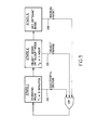
- Laser scanning system 10 operates in three scanning states as illustrated in the diagram of Fig. 3.
- the scanning states or “modes” are depicted as boxes in Fig. 3.
- the use of the electronic "or" gate symbol in Fig. 3 is meant to convey that laser scanning system 10 can only operate in one mode at any given time.
- the scanner In the continuous or scanning mode state, the scanner is completely on and ready to scan bar codes.
- the motors operate at full speed and the laser operates at full power.
- the AIM LED is continuously on and operates at 100% duty cycle in the preferred embodiment.
- a first timer implemented by microprocessor 24 functions to switch the scanner into the object sense or sleep mode if the scanner is unused for a period of time Ti. In a preferred embodiment T 2 is typically set to five minutes. If a bar code is successfully decoded while in the scanning mode state, a signal 26 is generated which directs the first timer to be reset. Thus the scanner will always remain in the scanning mode state when it is often being used (at least once every five minutes).
- the laser diode In the sleep mode, the laser diode is shut off and the motors operate at a fraction of their scanning speed while keeping the speed ratio constant.
- the AIM LED is blinked on and off at a frequency of about 20 KHz with a duty cycle of 50% in the preferred embodiment. Since the laser diode is off and the motors run at slower speeds, power consumption is reduced and the lifetime of these components is extended.
- the object sensor circuit 30 will detect that an object has been placed in the scan field.
- an object sensor trigger signal 28 is generated and used to direct the microprocessor to switch the laser scanning system back into the scanning mode. It should be mentioned that both object sensing and bar code decoding occur immediately after the object is introduced into the scan field. As will be explained in greater detail below, the object sensor circuit response time is quick enough so that the normal scanning process in not interrupted.
- a second timer implemented by microprocessor 24 functions to switch the laser scanner into the OFF or dead mode if no object sensor trigger signal 28 occurs in a time period T 2 .
- T 2 is typically set to one hour.
- the microprocessor 24 is directed to turn off all laser scanning system components that have limited lifetimes or have greater power consumption, e.g., the laser diode, motors, AIM LED.
- some of the lower power consuming components, such as the photodetector 12 may remain on in the dead mode. Other components that have a long operational lifetime may be left on in the dead mode.
- the laser scanner 10 usually enters the dead mode only after extended periods of non-use (e.g., one hour or more).
- a manual reset switch (not shown) is pushed to generate a manual reset signal 29.
- Manual reset signal 29 is coupled to microprocessor 24 which starts up the laser scanner system 10 in the scanning mode.
- the requirement of the object sensing circuit 30 of the present invention is to detect when any object is introduced into the scanner field. This is accomplished by detecting a change in the received signal level of the reflected light from the pulsed AIM LED illumination source.
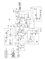
- the functional block diagram of object sensing circuit 30 shown in Fig. 4 and detailed circuit diagram of Fig. 5 illustrate how this is achieved.
- the bursts of pulses at the AIM LED blinking frequency are received by the photodetector 12 each time the field of view 17 passes through the stationary AIM LED spot 15.
- the received signal is the periodic convolution of the moving field of view 17 with the stationary pulsed AIM LED spot 15.
- the received signal is then amplified and filtered by amplifier/filter block 14 to obtain signal 21.
- the amplitude of signal 21 rises to a maximum when the field of view 17 overlaps the AIM LED spot 15.
- the blinking frequency of the AIM LED is much greater than the spatial frequency of the field of view. Referring back to Fig. 5, amplifier U1 adds gain to properly scale the received signal 21.
- the received signal 21 is used to generate a steady state background signal 34 by passing signal 21 through the peak detector/low pass filter combination 32 comprising electronic components CR1, R1, and C1 in the preferred embodiment.
- the components of peak detector 32 are chosen so that its time constant is large thus keeping the ripple 19 of steady state signal 34 to a minimum as Figure 7 illustrates.
- Steady state background signal 34 is proportional to the strength of the light reflected off of a background surface in the laser scan field. A change in the background signal 34 will occur when an object is placed in the path of the AIM LED spot 15 or the scan field. This change in signal 34 is detected by object sensing circuit 30 in the manner described below:
- the circuitry used to derive the negative threshold signal 37 is shown as block 38 in Figs. 4 and 5 and includes components U4, R5, R3, and C3.
- Amplifier U4 acts as a buffer to prevent loading of the peak detector 32.
- the values of the components are chosen so that the circuit time constant is greater than that of the peak detector/LPF combination 32. This ensures that the negative threshold signal 37 has a slow discharge time with respect to the steady state background signal 34.
- the negative threshold voltage signal 37 derived therefrom does not instantaneously change.
- the negative threshold signal 37 value is about 5% less than that of steady state signal 34. It should be mentioned that both positive and negative threshold signal magnitudes could be changed to suit a particular application. For example, it may be desirable to raise the threshold magnitudes in a noisy environment to thus eliminate false triggers due to the unwanted noise.
- the steady state background signal 34 and positive and negative threshold signals 35 and 37 are input to a window comparator 40 consisting of comparators U3, U5, pull-up resistor R12 and resistor pairs R8, R9, and R10, R11 which are used to add hysteresis to the comparators U3 and U5, respectively.
- the output of window comparator 40 i.e., object sensor trigger signal 28, is normally at a high voltage (or a logic "1 ”) in the sleep mode and drops to a low voltage (or a logic " 0 ”) when an object is detected by object sensor circuit 30.
- Typical detection waveforms are shown in Figures 6(a) and 6(b).
- Figure 6(a) shows the detection waveforms when an object with a reflectivity greater than that of the illuminated background surface is placed in the scan field of view 17.
- the steady state background signal 34 increases above the positive threshold voltage signal 35.
- trigger signal 28 goes low.
- Figure 6(b) shows the detection waveforms when an object with a reflectivity less than that of the illuminated background surface is placed in the scan field 17.
- the steady state background signal 34 decreases below the negative threshold voltage signal 37.
- Trigger signal 28 goes low.
- Trigger signal 28 is sent to microprocessor 24 which detects the change, and instantaneously responds by switching the laser scanning system back to the scanning mode.
- start-up circuits 42 and 44 as shown in Fig. 5, are connected at the positive and negative threshold generating circuits 36 and 38, respectively. These circuits function to prevent false object sensor triggering when the laser scanner system 10 switches from the scanning mode to the sleep mode after time period T i .
- Start-up circuit 42 comprises transistor Q1 coupled to the positive voltage power supply line via voltage divider network comprising resistors R14 and R15.
- the positive voltage power supply line is labelled as V cc in Fig. 5 and is generally about + 12.0 volts dc.
- start-up circuit 44 comprises transistor Q 2 coupled to the negative voltage power supply line labelled -V ee in Fig. 5.
- the voltage at -V ee is generally about -12.0 volts dc.
- a signal is present at terminal 45 of transistor Q2 that keeps transistor Q2 turned on, so that the negative threshold voltage signal 37 is pinned at voltage -V ee .
- the microprocessor sends a signal to the base terminal 45 of transistor Q2 which turns Q2 off. Once this is done, the negative threshold voltage signal 37 discharges to its sleep mode steady state level.
- Figure 8 illustrates the typical positive and negative threshold waveforms 35 and 37 as the scanner system switches from scanning mode to sleep mode.
- the time period labelled T, - 2 is the time at which the scanner system undergoes the transition from scanner mode to sleep mode.
- the present invention has been described with respect to linear or single bar codes, it is not limited to such embodiments, but may also be applicable to more complex scanning patterns and to stacked or two-dimensional bar codes such as Code 49 and similar symbologies. It is conceivable that the method of the present invention may also find application for use with various machine vision applications in which information is derived from other types of indicia such as characters or from the surface characteristics of the article being scanned.
- the elements of the scanner may be assembled into a very compact package that allows the scanner to be fabricated as a single printed circuit board of integral module.
- a module can interchangeably be used as the laser scanning element for a variety of different types of data acquisition systems.
- the module may be alternately used in a hand-held scanner, a table top scanner attached to a flexible arm or mounting extending over the surface of the table or attached to the underside of the table top, or mounted as a subcomponent or subassembly or a more sophisticated data acquisition system.
- the module would advantageously comprise a laser/optics subassembly mounted on a support, a scanning element such as a rotating or reciprocating mirror, and a photodetector component. Control or data lines associated with such components may be connected to an electrical connector mounted on the edge or external surface of the module to enable the module to be electrically connected to a mating connector associated with other elements of data acquisition system.
- An individual module may have specific scanning or decoding characteristics associated with it, e.g. operability at a certain working distance, or operability with a specific symbology or printing density. The characteristics may also be defined through the manual setting of control switches associated with the module.
- the user may also adapt the data acquisition system to scan different types of articles or the system may be adapted for different applications by interchanging modules on the data acquisition system through the use of the simple electrical connector.
- the scanning module described above may also be implemented within a self-contained data acquisition system including one or more such components as keyboard, display, data storage, application software, and data bases.
- a system may also include a communications interface to permit the data acquisition system to communicate with other components of a local area network or with the telephone exchange network, either through a modem or an ISDN interface, or by low power radio broadcast from the portable terminal to a stationary receiver.
Landscapes
- Physics & Mathematics (AREA)
- Engineering & Computer Science (AREA)
- Electromagnetism (AREA)
- Artificial Intelligence (AREA)
- Toxicology (AREA)
- General Health & Medical Sciences (AREA)
- Health & Medical Sciences (AREA)
- Computer Vision & Pattern Recognition (AREA)
- General Physics & Mathematics (AREA)
- Theoretical Computer Science (AREA)
- Optical Radar Systems And Details Thereof (AREA)
- Mechanical Optical Scanning Systems (AREA)
- Length Measuring Devices By Optical Means (AREA)
- Semiconductor Lasers (AREA)
- Facsimile Scanning Arrangements (AREA)
Applications Claiming Priority (2)
| Application Number | Priority Date | Filing Date | Title |
|---|---|---|---|
| US81253991A | 1991-12-23 | 1991-12-23 | |
| US812539 | 1991-12-23 |
Publications (2)
| Publication Number | Publication Date |
|---|---|
| EP0548451A2 true EP0548451A2 (fr) | 1993-06-30 |
| EP0548451A3 EP0548451A3 (en) | 1993-09-29 |
Family
ID=25209895
Family Applications (1)
| Application Number | Title | Priority Date | Filing Date |
|---|---|---|---|
| EP19920107662 Withdrawn EP0548451A3 (en) | 1991-12-23 | 1992-05-06 | Object sensing system for bar code laser scanners |
Country Status (7)
| Country | Link |
|---|---|
| US (1) | US5280162A (fr) |
| EP (1) | EP0548451A3 (fr) |
| JP (1) | JPH05292261A (fr) |
| KR (1) | KR940015925A (fr) |
| CN (1) | CN1052317C (fr) |
| CA (1) | CA2062106C (fr) |
| TW (1) | TW305977B (fr) |
Cited By (11)
| Publication number | Priority date | Publication date | Assignee | Title |
|---|---|---|---|---|
| WO1999038111A1 (fr) * | 1998-01-26 | 1999-07-29 | Intermec Ip Corp. | Dispositif de balayage modulaire sous forme de carte informatique |
| GB2346687A (en) * | 1999-02-12 | 2000-08-16 | Mitsubishi Electric Corp | Magnetic tape sensing system with continuous and pulsed modes |
| EP0910033A3 (fr) * | 1997-10-17 | 2001-01-10 | Welch Allyn, Inc. | Système de détection d'objets de formes à source de lumière régulée |
| US6657808B1 (en) | 1999-02-12 | 2003-12-02 | Mitsubishi Denki Kabushiki Kaisha | Sensing system with continuous and pulsed modes |
| WO2009024490A2 (fr) | 2007-08-21 | 2009-02-26 | Leica Microsystems Cms Gmbh | Procédé et dispositif d'éclairage ou d'irradiation d'un objet, d'un échantillon, ou analogue |
| EP1888172A4 (fr) * | 2005-05-17 | 2010-01-06 | Photon Therapy Systems Proprietary Ltd | Dispositif de therapie photonique |
| US20130062409A1 (en) * | 2011-09-14 | 2013-03-14 | Metrologic Instruments, Inc. | Scanner with wake-up mode |
| US8960551B2 (en) | 2013-01-07 | 2015-02-24 | Symbol Technologies, Inc. | Method of decoding barcode with imaging scanner having multiple object sensors |
| US9298963B2 (en) | 2010-12-23 | 2016-03-29 | Cognex Corporation | Mark reader with reduced trigger-to-decode response time |
| US10210369B2 (en) | 2010-12-23 | 2019-02-19 | Cognex Corporation | Mark reader with reduced trigger-to-decode response time |
| EP3537394A1 (fr) * | 2018-03-05 | 2019-09-11 | Toshiba Tec Kabushiki Kaisha | Dispositif et procédé de lecture de symboles |
Families Citing this family (84)
| Publication number | Priority date | Publication date | Assignee | Title |
|---|---|---|---|---|
| US5616908A (en) * | 1991-09-17 | 1997-04-01 | Metrologic Instruments, Inc. | Automatic countertop laser scanner with flickering laser scanner beam for improved visibility thereof during bar code symbol reading |
| US6286760B1 (en) | 1994-08-17 | 2001-09-11 | Metrologic Instruments, Inc. | Automatic hand-supportable laser projection scanner for omni-directional reading of bar code symbols within a narrowly confined scanning volume |
| US5796091A (en) * | 1993-11-24 | 1998-08-18 | Metrologic Instruments, Inc. | Automatic hand-supportable omnidirectional laser projection scanner with handle-controllable projection axis |
| US5340973A (en) * | 1990-09-17 | 1994-08-23 | Metrologic Instruments, Inc. | Automatic laser scanning system and method of reading bar code symbols using same |
| US5756982A (en) * | 1990-09-11 | 1998-05-26 | Metrologic Instruments, Inc. | Body-wearable automatic laser scanner with power-conserving control subsystem |
| US6607133B2 (en) | 1990-09-10 | 2003-08-19 | Metrologic Instruments, Inc. | Automatically-activated hand-supportable laser scanning bar code symbol reading system with data transmission activation switch |
| US5942743A (en) * | 1994-08-17 | 1999-08-24 | Metrologic Instruments, Inc. | Portable automatic hand-supportable omnidirectional laser projection scanner with power conserving control system |
| US6257492B1 (en) | 1990-09-10 | 2001-07-10 | Peter Bressler | Combination hand-held and counter-top omni-directional scanner |
| US5340971A (en) * | 1990-09-17 | 1994-08-23 | Metrologic Instruments, Inc. | Automatic bar code reading system having selectable long range and short range modes of operation |
| US6182898B1 (en) | 1993-11-24 | 2001-02-06 | Metrologic Instruments, Inc. | Bar code scanner with intuitive head aiming and collimated scan volume |
| US6651890B2 (en) | 1990-09-10 | 2003-11-25 | Sung Ho Byun | Combination hand-held and counter-top omnidirectional scanner |
| US6283375B1 (en) | 1990-09-10 | 2001-09-04 | Metrologic Instruments, Inc. | Automatically-activated hand-supportable laser scanning bar code symbol reading system with data transmission activation switch |
| US5844227A (en) * | 1993-11-24 | 1998-12-01 | Metrologic Instruments, Inc. | Automatic hand-supportable omnidirectional laser projection scanner with scan-head directed projection axis for intuitive hand-supported omnidirectional scanning of bar code symbols within a narrowly confined scanning volume extending thereabout |
| US5484992A (en) * | 1990-09-17 | 1996-01-16 | Metrologic Instruments, Inc. | Automatic hand-supportable laser scanner with flickering laser scanning beam to improve visibility thereof and beam-symbol alignment during bar code symbol presence detection |
| US5260553A (en) * | 1990-09-17 | 1993-11-09 | Metrologic Instruments, Inc. | Automatic hand-supportable laser bar code symbol scanner and method of reading bar code symbols using the same |
| US7156310B2 (en) * | 1990-09-17 | 2007-01-02 | Metrologic Instruments, Inc. | Automatically-activated hand-supportable laser scanning bar code symbol reading system with data transmission activation switch |
| US5883375A (en) * | 1991-09-17 | 1999-03-16 | Metrologic Instruments, Inc. | Bar code symbol scanner having fixed and hand-held modes |
| US6189793B1 (en) * | 1992-06-12 | 2001-02-20 | Metrologic Instruments, Inc. | Automatic laser projection scanner with improved activation controlling mechanism |
| US5502297A (en) * | 1992-10-22 | 1996-03-26 | Intermec Corporation | Method and apparatus for detecting the presence of a surface bearing a bar code symbol |
| US5449891A (en) * | 1993-05-10 | 1995-09-12 | Symbol Technologies, Inc. | Object sensor for an optical scanner |
| JP2740727B2 (ja) * | 1993-09-27 | 1998-04-15 | 株式会社テック | シンボル読取装置 |
| US6860427B1 (en) | 1993-11-24 | 2005-03-01 | Metrologic Instruments, Inc. | Automatic optical projection scanner for omni-directional reading of bar code symbols within a confined scanning volume |
| US6604684B1 (en) | 1993-11-24 | 2003-08-12 | Metrologic Instruments Inc. | Automatic optical projection scanner for omni-directional reading of bar code symbols within a confined scanning volume |
| JP3435200B2 (ja) * | 1993-11-29 | 2003-08-11 | ペンタックス株式会社 | 画像読取装置 |
| JP3477652B2 (ja) * | 1994-03-18 | 2003-12-10 | 富士通株式会社 | 情報処理端末装置 |
| JP3610116B2 (ja) * | 1994-04-14 | 2005-01-12 | キヤノン株式会社 | 画像記録装置 |
| EP0682304B1 (fr) * | 1994-05-11 | 1999-12-29 | CSEM Centre Suisse d'Electronique et de Microtechnique S.A. - Recherche et Développement | Microsystème à faible consommation d'énergie |
| US5815200A (en) * | 1994-07-26 | 1998-09-29 | Metanetics Corporation | Extended working range dataform reader with reduced power consumption |
| US5793967A (en) * | 1994-10-18 | 1998-08-11 | Hand Held Products, Inc. | Data collection and RF communications system and method of developing applications for same |
| US5659761A (en) * | 1994-10-18 | 1997-08-19 | Hand Held Products | Data recognition apparatus and portable data reader having power management system |
| US5612529A (en) * | 1994-10-31 | 1997-03-18 | Psc Inc. | System for bar code reading and scanning with automatic gain control |
| US5637854A (en) * | 1995-09-22 | 1997-06-10 | Microscan Systems Incorporated | Optical bar code scanner having object detection |
| US6575368B1 (en) * | 1996-01-31 | 2003-06-10 | Psc Scanning, Inc. | Multiple aperture data reader for multi-mode operation |
| JP3537946B2 (ja) * | 1996-02-26 | 2004-06-14 | 富士通株式会社 | バーコード読取装置の制御方法及びバーコード読取装置 |
| DE19700281A1 (de) * | 1997-01-07 | 1998-07-09 | Sick Ag | Optischer Codeleser mit einer optischen Abtastvorrichtung |
| US6976626B2 (en) * | 1997-09-16 | 2005-12-20 | Metrologic Instruments, Inc. | Wireless bar code symbol driven portable data terminal (PDT) system adapted for single handed operation |
| DE69806723T2 (de) | 1998-04-02 | 2003-06-12 | Datalogic S.P.A., Lippo Di Calderara Di Reno | Leseverfahren und Leser für einen optischen Kode |
| US6095417A (en) * | 1998-04-07 | 2000-08-01 | Eastman Kodak Company | Apparatus and method for reading bar codes on a moving web |
| DE19820575B4 (de) * | 1998-05-08 | 2012-03-29 | Leica Microsystems Cms Gmbh | Verfahren zum Betrieb einer pulsierenden Laserlichtquelle |
| US6601768B2 (en) | 2001-03-08 | 2003-08-05 | Welch Allyn Data Collection, Inc. | Imaging module for optical reader comprising refractive diffuser |
| US20030019934A1 (en) * | 1998-07-08 | 2003-01-30 | Hand Held Products, Inc. | Optical reader aiming assembly comprising aperture |
| DE29820891U1 (de) * | 1998-11-23 | 1999-01-14 | Satronic Ag, Dielsdorf | Lesestift |
| ES2274380T3 (es) * | 1998-12-03 | 2007-05-16 | Metrologic Instruments, Inc. | Sistema activado automaticamente de lectura de codigo de barras mediante escaneo manual por laser con interruptor de activacion de transmision de datos. |
| US7111786B2 (en) * | 1998-12-03 | 2006-09-26 | Metrologic Instruments, Inc. | Automatically-activated wireless hand-supportable laser scanning bar code symbol reading system with data transmission activation switch and automatic communication range dependent control |
| US7097105B2 (en) * | 1998-12-03 | 2006-08-29 | Metrologic Instruments, Inc. | Automatically-activated hand-supportable omni-directional laser scanning bar code symbol reader having a user-selectable linear scanning menu-reading mode supported by a stroboscopically-pulsed omni-directional laser scanning pattern for improved bar code symbol navigation and alignment during menu-reading operations |
| US6832725B2 (en) | 1999-10-04 | 2004-12-21 | Hand Held Products, Inc. | Optical reader comprising multiple color illumination |
| EP1226541A2 (fr) * | 1999-10-04 | 2002-07-31 | Welch Allyn Data Collection, Inc. | Module de transfert d'images pour lecteur optique |
| US7270274B2 (en) * | 1999-10-04 | 2007-09-18 | Hand Held Products, Inc. | Imaging module comprising support post for optical reader |
| US6502751B1 (en) | 2000-04-26 | 2003-01-07 | Ncr Corporation | Methods and apparatus for dual thresholding in processing of barcode signals |
| US6382511B1 (en) | 2000-04-26 | 2002-05-07 | Ncr Corporation | Methods and apparatus for digitizing and processing of analog barcode signals |
| JP2002063726A (ja) * | 2000-06-05 | 2002-02-28 | Nippon Precision Circuits Inc | 光ディスク再生装置のレーザーダイオード制御方法およびその回路 |
| JP2002051195A (ja) * | 2000-08-02 | 2002-02-15 | Canon Inc | 画像読み取り装置、その制御方法、画像処理システム、及び記憶媒体 |
| US7490774B2 (en) * | 2003-11-13 | 2009-02-17 | Metrologic Instruments, Inc. | Hand-supportable imaging based bar code symbol reader employing automatic light exposure measurement and illumination control subsystem integrated therein |
| JP2004516542A (ja) * | 2000-12-15 | 2004-06-03 | フィンガー システム インク. | ペン型光マウス装置及びペン型光マウス装置の制御方法 |
| US20030023855A1 (en) * | 2001-06-29 | 2003-01-30 | Keogh Kyle Dana | High security storage unit and biometric entry system |
| US6935564B2 (en) * | 2001-07-30 | 2005-08-30 | Bayer Healthcare Llc | Circuit and method for correcting influence of AC coupling |
| US6883711B2 (en) * | 2001-08-17 | 2005-04-26 | Borgwarner Inc. | Missing link/part detector employing scanning engine |
| US7138970B2 (en) * | 2002-12-09 | 2006-11-21 | Lockheed Martin Corporation | Method of LED life extension and end-of-life prediction |
| GB2404272B (en) * | 2003-07-25 | 2006-03-29 | Motorola Inc | Apparatus and method for image acquisition |
| US7128268B1 (en) * | 2003-11-04 | 2006-10-31 | Ncr Corporation | Bar code scanner having a mirrored spinner which operates at different speeds |
| US20050222801A1 (en) * | 2004-04-06 | 2005-10-06 | Thomas Wulff | System and method for monitoring a mobile computing product/arrangement |
| US20050258249A1 (en) * | 2004-04-29 | 2005-11-24 | Giebel James R | Imaging pixel array with programmable pixel aspect ratio for an optical code reader |
| KR101022221B1 (ko) * | 2004-07-30 | 2011-03-17 | 삼성전자주식회사 | 조리장치 및 조리장치의 제어방법 |
| US7009181B1 (en) * | 2004-08-31 | 2006-03-07 | Battelle Memorial Institute | Apparatus and method for OSL-based, remote radiation monitoring and spectrometry |
| EP2420954B8 (fr) * | 2004-12-01 | 2017-04-12 | Datalogic USA, Inc. | Lecteur de données à réglage automatique de l'exposition et procédés de fonctionnement d'un lecteur de données |
| US7389934B2 (en) * | 2005-05-27 | 2008-06-24 | International Business Machines Corporation | On-demand point-of-sale scanner access |
| US20080078839A1 (en) * | 2006-09-28 | 2008-04-03 | Edward Barkan | Electro-optical reader with object sensor |
| US7389933B2 (en) * | 2006-10-13 | 2008-06-24 | Symbol Technologies, Inc. | Triggerless electro-optical reader |
| US7832641B2 (en) * | 2007-05-24 | 2010-11-16 | Metrologic Instruments, Inc. | Scanner switched to active state by sensed movement in quiescent scanning mechanism |
| US20090140051A1 (en) * | 2007-11-30 | 2009-06-04 | Sik Piu Kwan | Method, device and system for off optical axis illumination |
| JP4644732B2 (ja) * | 2008-09-18 | 2011-03-02 | シャープ株式会社 | 光変調型検出装置および電子機器 |
| US7980470B2 (en) * | 2008-10-23 | 2011-07-19 | Symbol Technologies, Inc. | Adaptive power management in imaging systems |
| US8196834B2 (en) | 2010-07-12 | 2012-06-12 | Symbol Technologies, Inc. | Scan engine with integrated object sensor in electro-optical readers |
| US8342409B2 (en) | 2010-10-08 | 2013-01-01 | Symbol Technologies, Inc. | Object proximity sensor recessed into imaging reader |
| US8519744B2 (en) * | 2011-06-28 | 2013-08-27 | General Electric Company | Method of utilizing dual comparators to facilitate a precision signal rectification and timing system without signal feedback |
| US8387878B2 (en) * | 2011-07-26 | 2013-03-05 | Symbol Technologies, Inc. | Imager exposure, illumination and saturation controls in a point-of-transaction workstation |
| WO2013026180A1 (fr) * | 2011-08-23 | 2013-02-28 | Metrologic Instruments, Inc. | Système de lecture de symboles de code optique mettant en oeuvre un faisceau de visée laser généré par axicon |
| US8740085B2 (en) | 2012-02-10 | 2014-06-03 | Honeywell International Inc. | System having imaging assembly for use in output of image data |
| US9297900B2 (en) | 2013-07-25 | 2016-03-29 | Hand Held Products, Inc. | Code symbol reading system having adjustable object detection |
| US11216072B2 (en) | 2016-07-25 | 2022-01-04 | Sony Corporation | Information processing apparatus, information processing method, and program |
| CN108304741B (zh) | 2017-01-12 | 2023-06-09 | 手持产品公司 | 条形码扫描器中的唤醒系统 |
| JP2018181251A (ja) * | 2017-04-21 | 2018-11-15 | 東芝テック株式会社 | 読取装置およびプログラム |
| CN110595441B (zh) * | 2018-06-13 | 2021-10-12 | 杭州海康微影传感科技有限公司 | 瞄具 |
| US10824826B2 (en) | 2018-12-26 | 2020-11-03 | Datalogic Usa, Inc. | Utilization of imaging bar-code scanners for detecting anomalies with user scanning methods |
Family Cites Families (20)
| Publication number | Priority date | Publication date | Assignee | Title |
|---|---|---|---|---|
| US3925639A (en) * | 1974-03-25 | 1975-12-09 | Msi Data Corp | Method and apparatus for reading bar coded data wherein a light source is periodically energized |
| US4101072A (en) * | 1976-10-21 | 1978-07-18 | The Singer Company | Data-gathering device for scanning data having a variable amplitude modulation and signal to noise ratio |
| US4240064A (en) * | 1978-09-11 | 1980-12-16 | Ncr Corporation | Power limiting circuit for bar code reader |
| US4387297B1 (en) * | 1980-02-29 | 1995-09-12 | Symbol Technologies Inc | Portable laser scanning system and scanning methods |
| US4496831A (en) * | 1980-02-29 | 1985-01-29 | Symbol Technologies, Inc. | Portable laser scanning system and scanning methods |
| US4593186A (en) * | 1980-02-29 | 1986-06-03 | Symbol Technologies, Inc. | Portable laser scanning system and scanning methods |
| US4369361A (en) * | 1980-03-25 | 1983-01-18 | Symbol Technologies, Inc. | Portable, stand-alone, desk-top laser scanning workstation for intelligent data acquisition terminal and method of scanning |
| US4356389A (en) * | 1980-06-27 | 1982-10-26 | Motorola Inc. | Bar code scanner interface |
| US4575625A (en) * | 1983-09-27 | 1986-03-11 | Knowles Carl H | Integral hand-held laser scanner |
| US4521678A (en) * | 1984-01-13 | 1985-06-04 | Databar Corporation | Battery-powered optical bar code reader and voltage regulator therefor |
| US4639606A (en) * | 1984-10-26 | 1987-01-27 | Optel System Limited | Bar code scanner laser radiation exposure limit control system |
| US4694182A (en) * | 1986-02-27 | 1987-09-15 | Spectra-Physics, Inc. | Hand held bar code reader with modulated laser diode and detector |
| US4766297A (en) * | 1987-01-08 | 1988-08-23 | Recognition Equipment Incorporated | Dual mode stationary and portable scanning system |
| US5015833A (en) * | 1988-10-31 | 1991-05-14 | Symbol Technologies, Inc. | Scan board module for laser scanners |
| US5019698A (en) * | 1989-08-07 | 1991-05-28 | Photographic Sciences Corporation | Bar code reading systems having electrical power conservation and laser radiation power limiting means |
| US5059777A (en) * | 1989-09-21 | 1991-10-22 | Ncr Corporation | Scanning system presence sensing apparatus and method |
| JPH03129587A (ja) * | 1989-10-16 | 1991-06-03 | Fujitsu Ltd | 物品検出装置 |
| EP0424097B1 (fr) * | 1989-10-16 | 1995-08-09 | Fujitsu Limited | Dispositif de détection des articles et procédé de détection de l'article |
| US5321245A (en) * | 1989-10-27 | 1994-06-14 | Canon Kabushiki Kaisha | Data reading device and control system having data reading device |
| US5237161A (en) * | 1991-06-05 | 1993-08-17 | Psc, Inc. | System for automatically reading symbols, such as bar codes, on objects which are placed in the detection zone of a symbol reading unit, such as a bar code scanner |
-
1992
- 1992-02-28 CA CA002062106A patent/CA2062106C/fr not_active Expired - Lifetime
- 1992-05-06 EP EP19920107662 patent/EP0548451A3/en not_active Withdrawn
- 1992-11-18 JP JP4308511A patent/JPH05292261A/ja active Pending
- 1992-12-23 CN CN92114848A patent/CN1052317C/zh not_active Expired - Fee Related
- 1992-12-23 KR KR1019920025301A patent/KR940015925A/ko not_active Abandoned
-
1993
- 1993-03-01 TW TW082101462A patent/TW305977B/zh not_active IP Right Cessation
- 1993-06-25 US US08/082,527 patent/US5280162A/en not_active Expired - Lifetime
Cited By (17)
| Publication number | Priority date | Publication date | Assignee | Title |
|---|---|---|---|---|
| EP0910033A3 (fr) * | 1997-10-17 | 2001-01-10 | Welch Allyn, Inc. | Système de détection d'objets de formes à source de lumière régulée |
| WO1999038111A1 (fr) * | 1998-01-26 | 1999-07-29 | Intermec Ip Corp. | Dispositif de balayage modulaire sous forme de carte informatique |
| GB2346687A (en) * | 1999-02-12 | 2000-08-16 | Mitsubishi Electric Corp | Magnetic tape sensing system with continuous and pulsed modes |
| GB2346687B (en) * | 1999-02-12 | 2000-12-13 | Mitsubishi Electric Corp | Sensing system with continuous and pulsed modes |
| US6657808B1 (en) | 1999-02-12 | 2003-12-02 | Mitsubishi Denki Kabushiki Kaisha | Sensing system with continuous and pulsed modes |
| EP1888172A4 (fr) * | 2005-05-17 | 2010-01-06 | Photon Therapy Systems Proprietary Ltd | Dispositif de therapie photonique |
| US8913317B2 (en) | 2007-08-21 | 2014-12-16 | Leica Microsystems Cms Gmbh | Method and device for illuminating a sample in a laser microscope |
| WO2009024490A2 (fr) | 2007-08-21 | 2009-02-26 | Leica Microsystems Cms Gmbh | Procédé et dispositif d'éclairage ou d'irradiation d'un objet, d'un échantillon, ou analogue |
| WO2009024490A3 (fr) * | 2007-08-21 | 2009-05-07 | Leica Microsystems | Procédé et dispositif d'éclairage ou d'irradiation d'un objet, d'un échantillon, ou analogue |
| US9298963B2 (en) | 2010-12-23 | 2016-03-29 | Cognex Corporation | Mark reader with reduced trigger-to-decode response time |
| US9721134B2 (en) | 2010-12-23 | 2017-08-01 | Cognex Corporation | Mark reader with reduced trigger-to-decode response time |
| US10210369B2 (en) | 2010-12-23 | 2019-02-19 | Cognex Corporation | Mark reader with reduced trigger-to-decode response time |
| US8590789B2 (en) * | 2011-09-14 | 2013-11-26 | Metrologic Instruments, Inc. | Scanner with wake-up mode |
| US20130062409A1 (en) * | 2011-09-14 | 2013-03-14 | Metrologic Instruments, Inc. | Scanner with wake-up mode |
| US8960551B2 (en) | 2013-01-07 | 2015-02-24 | Symbol Technologies, Inc. | Method of decoding barcode with imaging scanner having multiple object sensors |
| EP3537394A1 (fr) * | 2018-03-05 | 2019-09-11 | Toshiba Tec Kabushiki Kaisha | Dispositif et procédé de lecture de symboles |
| US11361180B2 (en) | 2018-03-05 | 2022-06-14 | Toshiba Tec Kabushiki Kaisha | Symbol reading device and method |
Also Published As
| Publication number | Publication date |
|---|---|
| CA2062106A1 (fr) | 1993-06-24 |
| CA2062106C (fr) | 2002-08-20 |
| CN1080417A (zh) | 1994-01-05 |
| KR940015925A (ko) | 1994-07-22 |
| TW305977B (fr) | 1997-05-21 |
| US5280162A (en) | 1994-01-18 |
| CN1052317C (zh) | 2000-05-10 |
| JPH05292261A (ja) | 1993-11-05 |
| EP0548451A3 (en) | 1993-09-29 |
Similar Documents
| Publication | Publication Date | Title |
|---|---|---|
| US5280162A (en) | Object sensing system for bar code laser scanners | |
| CA1336620C (fr) | Systeme de balayage a intensite d'eclairement et/ou a angle de balayage reglables | |
| US5210398A (en) | Optical scanner with extended depth of focus | |
| US5229591A (en) | Scanning system with adjustable light output and/or scanning angle | |
| US6123264A (en) | Apparatus and method for determining a distance to a target | |
| US5302813A (en) | Multi-bit digitizer | |
| US5324924A (en) | Bar code decoder with changeable working ranges | |
| EP0690404B1 (fr) | Dispositif et méthode d'exploration électro-optique pour lire des signes distinctifs | |
| US5250791A (en) | Scanning system with adjustable light output and/or scanning angle | |
| US5449893A (en) | Digitizer for bar code reader | |
| EP0517957B1 (fr) | Système de balayage à laser et méthode de balayage pour lire des codes à barres | |
| US5923021A (en) | Light collection systems in electro-optical readers | |
| US5591953A (en) | Countertop bar code symbol reading system having automatic hand-supportable bar code symbol reading device and stand for supporting projected scan field thereof | |
| US5859418A (en) | CCD-based bar code scanner with optical funnel | |
| US5396053A (en) | Method of adjusting electrical circuit parameters during manufacture of a bar code scanner | |
| EP0653721B1 (fr) | Lecteur de code à barres | |
| JPH04286382A (ja) | レーザーの寿命延長装置および方法 | |
| US5996895A (en) | Scanning system with adjustable light output and/or scanning angle | |
| US7562826B2 (en) | Scan engine with dual chip architecture for use in electro-optical readers | |
| US5798515A (en) | Optical scanner with fast zoom capability and scanning system | |
| EP0548958B1 (fr) | Appareil de balayage à laser | |
| US6871786B1 (en) | Method and apparatus for reading and writing indicia such as bar codes using a scanned laser | |
| KR960003056B1 (ko) | 바코드를 판독하기 위한 라스터 주사시스템과 주사장치 및 주사방법 | |
| CA2134698A1 (fr) | Numeriseur pour lecteur de codes a barres |
Legal Events
| Date | Code | Title | Description |
|---|---|---|---|
| PUAI | Public reference made under article 153(3) epc to a published international application that has entered the european phase |
Free format text: ORIGINAL CODE: 0009012 |
|
| AK | Designated contracting states |
Kind code of ref document: A2 Designated state(s): AT DE ES FR GB IT |
|
| PUAL | Search report despatched |
Free format text: ORIGINAL CODE: 0009013 |
|
| AK | Designated contracting states |
Kind code of ref document: A3 Designated state(s): AT DE ES FR GB IT |
|
| RIN1 | Information on inventor provided before grant (corrected) |
Inventor name: MARWIN, GREGG |
|
| 17P | Request for examination filed |
Effective date: 19940329 |
|
| 17Q | First examination report despatched |
Effective date: 19960327 |
|
| GRAG | Despatch of communication of intention to grant |
Free format text: ORIGINAL CODE: EPIDOS AGRA |
|
| RAP1 | Party data changed (applicant data changed or rights of an application transferred) |
Owner name: SYMBOL TECHNOLOGIES, INC. |
|
| APAB | Appeal dossier modified |
Free format text: ORIGINAL CODE: EPIDOS NOAPE |
|
| APBJ | Interlocutory revision of appeal recorded |
Free format text: ORIGINAL CODE: EPIDOS IRAPE |
|
| GRAG | Despatch of communication of intention to grant |
Free format text: ORIGINAL CODE: EPIDOS AGRA |
|
| GRAH | Despatch of communication of intention to grant a patent |
Free format text: ORIGINAL CODE: EPIDOS IGRA |
|
| GRAH | Despatch of communication of intention to grant a patent |
Free format text: ORIGINAL CODE: EPIDOS IGRA |
|
| STAA | Information on the status of an ep patent application or granted ep patent |
Free format text: STATUS: THE APPLICATION IS DEEMED TO BE WITHDRAWN |
|
| 18D | Application deemed to be withdrawn |
Effective date: 20000125 |