EP0548510A2 - Système de direction assistée hydraulique à réaction assistante variable - Google Patents
Système de direction assistée hydraulique à réaction assistante variable Download PDFInfo
- Publication number
- EP0548510A2 EP0548510A2 EP92118728A EP92118728A EP0548510A2 EP 0548510 A2 EP0548510 A2 EP 0548510A2 EP 92118728 A EP92118728 A EP 92118728A EP 92118728 A EP92118728 A EP 92118728A EP 0548510 A2 EP0548510 A2 EP 0548510A2
- Authority
- EP
- European Patent Office
- Prior art keywords
- pressure
- steering
- valve
- reaction
- movable part
- Prior art date
- Legal status (The legal status is an assumption and is not a legal conclusion. Google has not performed a legal analysis and makes no representation as to the accuracy of the status listed.)
- Granted
Links
- 238000006243 chemical reaction Methods 0.000 title claims abstract description 82
- 239000012530 fluid Substances 0.000 claims abstract description 22
- 230000007246 mechanism Effects 0.000 claims description 11
- 238000006073 displacement reaction Methods 0.000 claims description 9
- 230000008859 change Effects 0.000 claims description 7
- 230000006870 function Effects 0.000 claims description 5
- 238000007667 floating Methods 0.000 claims description 4
- 230000000694 effects Effects 0.000 claims description 3
- 230000001133 acceleration Effects 0.000 description 10
- 238000004891 communication Methods 0.000 description 7
- 230000003750 conditioning effect Effects 0.000 description 4
- 230000008878 coupling Effects 0.000 description 4
- 238000010168 coupling process Methods 0.000 description 4
- 238000005859 coupling reaction Methods 0.000 description 4
- 230000003247 decreasing effect Effects 0.000 description 4
- 238000010586 diagram Methods 0.000 description 4
- 230000007423 decrease Effects 0.000 description 2
- 230000001419 dependent effect Effects 0.000 description 2
- 230000036316 preload Effects 0.000 description 2
- 238000010276 construction Methods 0.000 description 1
- 239000002184 metal Substances 0.000 description 1
- 230000004048 modification Effects 0.000 description 1
- 238000012986 modification Methods 0.000 description 1
- 230000035807 sensation Effects 0.000 description 1
- 238000013022 venting Methods 0.000 description 1
- 238000004804 winding Methods 0.000 description 1
Images


Classifications
-
- B—PERFORMING OPERATIONS; TRANSPORTING
- B62—LAND VEHICLES FOR TRAVELLING OTHERWISE THAN ON RAILS
- B62D—MOTOR VEHICLES; TRAILERS
- B62D5/00—Power-assisted or power-driven steering
- B62D5/06—Power-assisted or power-driven steering fluid, i.e. using a pressurised fluid for most or all the force required for steering a vehicle
- B62D5/08—Power-assisted or power-driven steering fluid, i.e. using a pressurised fluid for most or all the force required for steering a vehicle characterised by type of steering valve used
-
- B—PERFORMING OPERATIONS; TRANSPORTING
- B62—LAND VEHICLES FOR TRAVELLING OTHERWISE THAN ON RAILS
- B62D—MOTOR VEHICLES; TRAILERS
- B62D6/00—Arrangements for automatically controlling steering depending on driving conditions sensed and responded to, e.g. control circuits
- B62D6/02—Arrangements for automatically controlling steering depending on driving conditions sensed and responded to, e.g. control circuits responsive only to vehicle speed
Definitions
- This invention relates to power steering systems for automotive vehicles wherein the steering effort required for steering manoeuvres at low vehicle speeds is reduced and at high speeds is increased, thus providing an optimum steering pressure versus steering torque relationship.
- the invention comprises improvements in a power steering gear of the kind disclosed in United States Patents 4,434,866, 4,586,582, 4,570,735, 4,561,521, and 4,570,736.
- Each of these patents is assigned to the assignee of the present invention.
- Each of these prior art constructions comprises a power steering system having a fluid motor with a double-acting piston which cooperates with a fluid cylinder of the motor to define two opposed working chambers.
- a power steering pump, driven by the vehicle engine, includes a pressure control valve and a flow control valve so that the flow delivered by the pump to the steering system remains constant regardless of varying engine speed.
- the fluid circuit of which the motor and the pump are a part, includes a rotary valve assembly having an inner valve member connected mechanically to a driver-controlled steering shaft and a rotary valve sleeve.
- the valve assembly comprises registering valve lands that control pressure distribution from the pump to the motor whereby the angular disposition of the dirigible wheels of the vehicle is controlled with a steering effort that is assisted by the steering pressure forces developed by the motor.
- the inner and outer valve elements define registering valve lands which cooperate one with respect to the other, to define a variable area flow path between the outlet side of the pump and the flow return side. Provision is made for connecting each of the opposed working chambers of the fluid motor to the rotary valve assembly so that the pressure developed in the pressure passages connecting the pump with the motor may be distributed to each of the working chambers selectively. When one chamber is pressurised and the other exhausted, the vehicle is adapted to turn in one direction. Upon a reversal in the direction of the pressure differential in the fluid motor, the steering direction reverses.
- Torque is transferred from the steering shaft to the driving pinion of the steering gear through a torsion bar.
- Upon deflection of the bar relative angular motion of the elements of the steering valve occurs.
- the steering torque is determined by the torsion bar deflection as is the steering effort or steering assist provided by the fluid motor.
- the improved steering system of the present invention includes a rotary spool-type steering valve with a floating inner spool valve element wherein reaction pistons are provided in the valve mechanism to establish a resistance to relative movement of the valve elements depending upon steering pressure.
- reaction pistons are provided in the valve mechanism to establish a resistance to relative movement of the valve elements depending upon steering pressure.
- steering torque is increased. This increase in steering torque is determined by modulating steering pressure that acts on the reaction pistons that opposes the relative movement of the steering valve elements.
- Patent 4,561,521 which as mentioned earlier is identified as a low-speed mode and a high-speed mode, the system of the present invention makes it possible to shape the pressure-versus-torque relationship so that an optimum relationship can exist for all vehicle speeds and for all steering torque demands.
- the reaction pressure that acts on the reaction pistons can be determined by two hydraulic reaction pressure modulator valves and by a speed-sensitive proportional solenoid valve.
- the solenoid valve selects the appropriate relationship between pressure and torque for any vehicle speed, and the two pressure modulator valves establish the appropriate shape of the pressure versus torque relationship that is selected by the proportional solenoid valve.
- a pressure control solenoid shapes the pressure/torque boost curves by means of a programmed electronic processor using software that controls the functional relationship between the hydraulic reaction pressure and the steering pressure, thus eliminating the need for the separate hydraulic reaction pressure modulator valves.
- Numeral 10 in Figure 1 designates a driver-controlled steering shaft for a motor vehicle.
- Numeral 12 generally designates, in schematic form, a fluid motor having a pressure-actuated piston 14 connected to the vehicle traction wheels through a suitable steering linkage (not shown) and to a pinion 16, which is adapted to be connected by means of a rack-and-pinion assembly to the piston 14.
- Steering pressure of the power steering pump is adapted to deliver working pressure to steering pressure input port 17.
- the pump and the associated fluid circuit will be described more fully with reference to Figure 4.
- the steering gear includes a cylindrical housing 18 in which the port 17 is formed.
- a right-turn port 20 and a left-turn port 22 also are formed in the housing 18. These are connected, respectively, to pressure chambers 22 and 24 for the fluid motor 12.
- FIG. 1 shows a valve assembly identified generally by reference numeral 26.
- This valve assembly comprises a valve sleeve 28 situated in a valve cylinder 30.
- a drive pin 32 formed in the pinion 16 extends radially with respect to the axis of the sleeve 28 and engages an end groove 34 in one end of the sleeve 28.
- the sleeve 28 moves with the pinion 16 within the steering valve cylinder 30.
- the pinion 16 is journalled by a bearing 36 in bearing opening 38 formed in the housing 18.
- a fluid seal 40 seals the pinion and the housing opening through which the pinion extends.
- Steering shaft 10 is journalled by bearing 42 on the right-hand side of the sleeve 28 as shown in Figure 1.
- Bearing 42 provides a bearing support as it is carried by the cylinder 30 of the housing 18 as shown at 44.
- Left-turn passage 46 in the sleeve 28 communicates with annular groove 48, which in turn communicates with left-turn passage 22.
- right-turn port 50 communicates with an annular groove 52 in sleeve 28.
- Groove 52 in turn communicates with right-turn port 20.
- Seal rings are disposed in seal ring grooves situated on either side of the groove 52 as shown at 54 and 56.
- seal ring grooves receive seal rings on either side of the left-turn port 22, as shown at 58 and 60.
- a vent port 62 in the sleeve 28 communicates with a vent port 106 in the housing 18. This provides a venting of the interior of the valve cylinder 30 between the seal 40 and a corresponding lip seal 63.
- the valve sleeve 28 has a central opening 64 in which is formed internal valve lands 66. These register with external valve lands 68 formed on a valve spool 70, the latter being piloted at each of its axial ends in the opening 64.
- Valve sleeve 28 is piloted in the housing 18 as pilot surface 72 registers with the opening 44.
- the other end of the sleeve 28 is piloted at 73, as seen at the left-hand side of the sleeve 28 shown in Figure 1.
- the spool 70 is provided with an angularly spaced slot 74 which registers with a radial projections 76 formed on the torque input shaft 10, the latter being piloted by bearing element 78 on the left hand of the torsion bar 80.
- Torque input shaft 10 is drivably connected to the torsion bar 80 at 82.
- the left-hand end of the torsion bar 80 is splined as shown at 84 to an internally splined opening in the end of the pinion 16.
- the left end of the torque input shaft 10 is provided with dog coupling teeth in the form of angularly spaced slots 86 which register with corresponding internal coupling teeth 88 in the right end of the pinion 16, thus forming a lost motion connection between the shaft 10 and the pinion 16.
- the degree of relative motion established by the dog coupling will permit the torsion bar to transmit torque from the input shaft 10 to the pinion 16 up to a limit. When that limit is reached, torque is transferred directly from the shaft 10 to the pinion 16 through the dog coupling.
- any misalignment of the sleeve 28 with respect to the axis of the pinion 16 can be accommodated by reason of the articulation that is permitted by the end bearing supports at the right end of the sleeve as shown at 72 and the left end of the sleeve as shown at 73.
- the spool 70 will precisely register with the sleeve 28 because of the articulated connection between the spool 70 and the input shaft 10 provided by the slot 74 and the projection 76.
- the spool thus can be considered to be a floating valve spool which always registers precisely with the internal valve lands of the sleeve 28 regardless of any slight misalignment of the sleeve with respect to the pinion 16.
- pressure input port 17 communicates with a groove 90 in the sleeve 28. This, in turn, communicates with radial ports 92.
- Valve spool 70 is provided with radial ports 94, as seen in Figure 3, which are situated between internal valve lands 96 and 98 formed in the valve sleeve. External valve lands 100 and 102 formed in the spool 70 register, respectively, with internal lands 96 and 98, thus forming a flow passage on either side of the radial ports 94.
- annular space 104 is a flow return passage that communicates with return flow passage 106 seen in Figure 1.
- valve spool will shift slightly in a clockwise direction relative to the valve sleeve seen in Figure 3, thereby enlarging the flow area between passage 92 and port 50 and simultaneously decreasing the flow area between passage 92 and the port 46 leading to the right-turn side of the fluid motor.
- This provides a steering assist which complements the steering torque applied to the pinion through the torsion bar.
- the sleeve is provided with a pair of opposed reaction pressure cylinders 106 and 108.
- a reaction piston 110 is slidably disposed in cylinder 106, and a corresponding piston 112 is slidably disposed in reaction cylinder 108.
- Piston 110 and cylinder 106 define a reaction pressure chamber 114 which communicates with a reaction pressure port (not shown) formed in the housing 18.
- piston 112 and cylinder 108 define a reaction pressure chamber 116 which communicates with the same reaction pressure port formed in the housing 18.
- Projection 76 on the steering shaft 10 includes a reaction surface 118 which is engaged by the piston 112 and a reaction surface 120 which is engaged by the piston 110.
- a reaction pressure force developed on the piston 112 causes a counterclockwise torque to be applied to the shaft 10.
- piston 110 will apply a clockwise torque to the shaft 10 as viewed in Figure 2.
- piston 110 engages a stop shoulder 122 formed in the sleeve 28, and piston 112 engages a stop shoulder 124 also formed in the sleeve 28.
- piston 110 and 112 assume the position shown in Figure 2.
- one of the pistons 110 or 112 is displaced from its stop 106 or 124 and the pressure in the reaction pressure chamber 114 and 116 resists relative angular displacement of the shaft with respect to the sleeve.
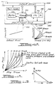
- the characteristic curves for low-vehicle speeds might correspond to curve 126.
- the characteristic curve representing the torque and pressure differential relationship will correspond to the curve 136 in Figure 7. It is seen, therefore, that by properly tailoring the pressure in the reaction pressure cylinders of my present invention it is possible to tailor the characteristic curves so that any of one of a family of curves between the maximum and minimum values can be achieved as the vehicle speed changes.
- Other vehicle characteristics measured by other operating variables such as engine throttle position, vehicle lateral acceleration and road surface slope can be used to modify the relationship of torque to steering pressure differential. This control of the reaction pressure is achieved electronically as will be described with reference to Figures 4, 8, 9, 10 and 11.
- the pressure chambers 114 and 116 communicate with an annular space 126 as seen in Figure 1, which surrounds the sleeve. Space 126 is sealed from the adjacent fluid passages by a pair of axially spaced seal rings 128 and 130.
- the sleeve 28, as seen in Figure 2, is provided with a threaded opening 132 which receives a bolt 134 which retains a stop washer 136 located in the path of movement of piston 110.
- the stop washer 136 limits the left-hand movement of the piston 110 as viewed in Figure 2.
- a threaded opening 138 is formed in the opposite side of the opening 132. This opening receives a bolt 140 which retains another stop washer 142 which limits the movement of the piston 112 in a right-hand direction.
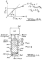
- Shown in Figure 8 is a hydraulic reaction pressure control system that comprises three main elements; namely, a modulator valve 144, a pressure limiter valve 146 and a proportional solenoid valve 148.
- Modulator valve 144 comprises a valve spool 150 having spaced valve lands 152 and 154, which respectively register with valve ports formed in valve chamber 156 which communicate with a steering pressure inlet port 158 and a return port 160.
- Feedback pressure passage 166 distributes steering pressure to the upper side of land 152 to provide a pressure force that opposes the force of valve spring 164.
- feedback passage 158 communicates with the lower side of land 152 to establish a pressure force that assists the force of spring 164.
- a pressure will be developed by the modulator valve in outlet passage 168 that is functionally related to steering pressure in passage 158 and to the calibration of the valve lands and the valve spring.
- the output pressure in passage 168 is delivered to the pressure limiter valve 146, which comprises valve spool 170 having spaced lands 172 and 174 and a valve spring 176.
- Return port 178 registers with land 174, and a pressure inlet port which forms a part of passage 168 registers with land 172.
- Feedback pressure passage 180 extends from the output side of the pressure limiter valve to the upper end of the land 172.
- Valve 146 thus establishes a limiting pressure in outlet passage 182, which communicates with valve chamber 182A intermediate the lands 172 and 174.
- the hydraulic reaction pressure that is distributed to pressure chambers 114 and 116 behind the pistons 110 and 112 is developed by the proportional solenoid valve 148.
- Output pressure port for the hydraulic reaction pressure shown at 184 communicates with annular space 126 surrounding the valve sleeve 128 through a port (not shown) in the housing 18 seen in Figure 1.
- the proportional solenoid valve comprises a valve spool 186 having spaced lands 188 and 190 situated on opposite sides of the hydraulic reaction pressure outlet port 184. Land 190 registers with port 192 that communicates with the limiter valve outlet pressure passage 182 and land 188 registers with a return port. Valve spring 194 urges the valve element 186 in an upward direction, thereby tending to open the return port and reducing the pressure in hydraulic reaction pressure port 184. Spring 194 also tends to open communication between outlet port 184 and the pressure limiter pressure passage 182.
- a solenoid that is proportional to vehicle speed is identified generally by reference numeral 196. It includes a solenoid winding surrounding a solenoid armature 198 which engages valve spool 186 and establishes a solenoid force on the valve spool 186 that opposes the force of the spring 194. Decreases in vehicle speed will increase the force that opposes the force of the spring 194.
- the series related valves regulate and then reregulate the steering pressure in passage 158 to produce a hydraulic reaction pressure in passage 184.
- the degree to which the steering pressure is modified depends upon the calibration of the valves and the valve spring so that the so-called shape of the boost curve representing steering pressure versus steering torque versus vehicle speed is the optimum operating condition.
- the characteristic curve for the pressure boost function may be as shown in Figure 7 where the pressure differential across the steering motor is shown plotted against steering torque for various vehicle speeds. At low vehicle speed, the pressure curve rises quickly as the torque increases. The curves progressively become flatter and have a lower slope as the vehicle speed increases.
- Figure 9 shows a preferred embodiment of the modulator valve illustrated schematically in Figure 8.
- feedback passage 166 is situated at the center of the valve spool 150 and communicates with outlet port 168.
- Return port 160 communicates with central opening 200 in the valve spool 154, which communicates with the lower-hand end of the valve chamber 156 that is occupied by spring 164.
- valve land 152 is formed with a double diameter, the smaller diameter portion 202 registering with inlet pressure port 158. A small degree of overlap at the metering edges of the valve land surfaces is provided as indicated by the label in Figure 9.
- the calibration of the pressure modulator valve in Figure 9 can be tailored by appropriately varying the diameter of the large diameter portion 204 of the land 152 relative to the diameter of land 154 and by appropriately varying the spring rate of spring 164.
- valve land 154 is provided with a small metal overlap as indicated by the label in Figure 9 at the location where the land 154 registers with the internal land for outlet port 168.
- Figure 9A shows a typical characteristic curve for the relationship between control pressure P2 and the inlet pressure P1.
- pressure P1 will equal pressure P2 as indicated by the plot of Figure 9A.
- the slope of the pressure line shown in Figure 9A is modified so that it has a lesser slope.
- greater changes in the value of P1 are required to effect a given change in the value of P2.
- the relationship between the spring force, the areas and the pressures are indicated by the formula for P2 set forth in Figure 9A.
- Figure 9B shows how the modulator valve shapes the high-speed pressure-torque boost curve having essentially linear slopes which increase to new chosen values at chosen break-point steering pressures.
- a second modulator valve can replace the limiter valve.
- FIG. 10 A preferred embodiment of the proportional solenoid valve of Figure 8 is indicated in Figure 10.
- the return port communicates through a central passage 206 with each of the ends of the valve spool 186.
- the output port 184 which carries a reaction pressure outlet pressure P4, communicates with the valve chamber 208 at a location between the lands 188 and 190.
- Land 188 registers with return passage 192 through a tapered metering edge 210 formed on the land 188.
- a metering edge 212 formed on the land 190 provides controlled communication between reaction pressure outlet port 184 and inlet port 192.
- the shape of the characteristic curves representing the relationship between reaction pressure and input pressure P3 can be modified by calibrating the flow restriction established by the tapered edges of the valve lands as shown at 210 and 212.
- valve land tapered edges can be provided with a series of grooves defining small orifices, as indicated by the legend shown in Figure 10.
- the resulting variation in the output pressure P4 can be modified, thus avoiding abrupt changes in output pressure for a given change in the solenoid force.
- an electronically controlled steering system for developing a reaction pressure for the reaction pistons includes an electronic microprocessor.
- the magnitude of the reaction pressure is dependent upon the output signal developed by the microprocessor and the resulting solenoid driver signal for the solenoid valve.
- the system senses the output load, which is the steering pressure differential at the steering motor, and the vehicle speed to control the steering effort in accordance with the calibration of the electronic module for the microprocessor and the software program by means of which the electronic control unit of the microprocessor responds to the vehicle operating parameters.
- the software may cause instructions to be issued to the electronic control unit to develop a modification for the reaction pressure depending upon lateral acceleration, for example, or possibly other vehicle variables such as steering wheel angle, road grade and slope or engine throttle position in addition to the lateral acceleration of the vehicle.
- lateral acceleration becomes of importance during turning manoeuvres of the vehicle and when the vehicle is subjected to transverse forces such as wind gusts as the vehicle is travelling in a straight-ahead direction.
- transverse forces such as wind gusts as the vehicle is travelling in a straight-ahead direction.
- Such lateral acceleration forces may occur also when the vehicle is operated on a road surface with a changing crown or a changing lateral slope.
- the electronic microprocessor makes it possible, therefore, for the steering system to control the steering effort by increasing the hydraulic reaction forces developed by the reaction pistons rather than by controlling the effort due to changes in the torsion bar twist as in the case of the steering systems shown in prior art patents of the type previously described such as U.S. Patents 4,570,735 and 4,570,736. It is possible also to achieve that degree of control while reducing to a minimum the angular displacement of the inner valve member relative to the internal lands formed on the valve sleeve. Thus, valve friction is reduced and the hydraulic circuit for the valve elements is substantially simplified.
- a flow return passage 222 returns the steering fluid to the pump from exhaust port 224 in the solenoid valve. Hydraulic reaction pressure is distributed from port 226 in the solenoid valve 220 through passage 228 which communicates with the pressure chambers of the reaction pistons and with the space 126 shown in Figure 1.
- the magnitude of the steering pressure is sensed by a pressure sensor 230 which may be any of a number of well known pressure sensors capable of developing a pressure signal that is proportional to the input pressure in port 17 of the steering gear. This achieves a closed-loop control circuit wherein the processor may adjust reaction pressure in accordance with pressure changes detected by the sensor 230.
- the sensor 230 acts as a pressure-to-voltage transducer and distributes a signal voltage through line 232 to a microprocessor 234.
- Microprocessor 234 develops a signal in line 236, which is distributed to the solenoid valve 220, as indicated in the schematic diagram of Figure 4.
- the input signal conditioning circuit for the microprocessor 234 receives a vehicle speed signal through line 238 from speed sensor 240. If desired, other input signals can be distributed to the microprocessor 234 such as the signal developed by a lateral acceleration sensor 242, the signal input being shown at 243.
- the microprocessor 234 includes an input signal conditioning circuit 244 which receives the input signals such as the speed sensor signal and the lateral acceleration sensor signal.
- the microprocessor 234 further includes a central processor unit or "CPU" 246 which is under the control of a program counter 248.
- the CPU will fetch a signal from the input signal conditioning portion 244 and transfer it to a buffer storage area such as the buffer 250. It then addresses the memory portion 252 to obtain data stored in memory for comparison to the input signal value stored in the buffer. The result of that comparison is a computation that results in the transfer of an output signal to the output driver portion of the processor as shown in 254.
- the data that is stored in memory is the optimum functional relationship between steering pressure and torque, as indicated schematically in Figure 4.
- Various values for steering torque for each value of steering pressure is stored in memory and for each of the family of vehicle speeds. That data represents the optimum steering torque for the particular driving conditions that are sensed by the sensors, including the sensor 240 and the sensor 242.
- the lateral acceleration sensor 242 develops a signal that is delivered also to the input signal conditioning portion 244 where it is fetched and compared to a memory value such as that illustrated schematically in Figure 4.
- the schematic illustration in Figure 4 shows a plot in the relationship between steering pressure and lateral acceleration.
- the value of steering torque can be modified by the microprocessor 234 without a corresponding deflection of the torsion rod in order to accommodate varying operating conditions as measured by the various sensors such as the speed sensor 240 and the lateral acceleration sensor 242.
- Figure 5 shows in schematic form the relationship between the input shaft and the reaction pistons 110 and 112 when the steering gear is in the so-called on-center position. At that time, the pistons 110 and 112 engage their respective stops 122 and 124.
- Figure 6 shows the same elements indicated in Figure 5, but the input shaft has been turned upon application of torque to the steering wheel so that piston 124 is displaced as is the corresponding piston on the opposite side of the input shaft axis. The pressure force acting on the piston 112 by the reaction pressure opposes the relative displacement of the shaft 10 relative to the sleeve 28.
- a "preload” reaction pressure will prevent any valve motion until it is overcome by a “preload” steering torque (see Figure 9B).
- the desired values may be selected by adjusting the pressure drop across the rotary valve.
- FIG 11 shows in schematic form in more detail the solenoid valve 220 illustrated schematically in the system of Figure 4.
- Steering pressure is delivered to the steering valve 220 through steering pressure passage 218.
- the solenoid valve comprises a valve spool 256 slidable disposed in valve chamber 258.
- Valve land 260 formed on the valve spool 258 registers with steering pressure port 218.
- Reaction pressure is distributed to the chamber 258 at a location between land 260 and a second land 262, the latter registering with fluid return port 224.
- Reaction pressure is distributed to the upper side of the land 260 through an internal passage 264. This creates a pressure force on the valve spool 256 which is opposed by valve spring 266. Return pressure acts on the lower side of the land 262.
- the speed signal delivered to solenoid 268 is zero.
- the signal delivered to the solenoid 268 is a maximum. In a preferred embodiment, the maximum value is one ampere.
- Figure 11A shows the relationship between steering torque and steering pressure when the pressure torque curves are shaped using steering pressure and vehicle speed as variables.
- the steering torque will vary until a desired torque is achieved at a given vehicle steering pressure and speed.
- the curves are shaped so that the steering torque varies uniformly along a generally parabolic line for various vehicle speeds, thereby providing improved road feel.
- the steering sensation is determined by the actual vehicle steering requirements under a variety of steering conditions rather than the steering requirements determined only by vehicle speed.
- Figure 11B shows the relationship between amperage for the solenoid and the reaction pressure. It should be noted that the relationship is generally linear and that it has a negative slope so that the maximum amperage corresponds to a minimum reaction pressure.
Landscapes
- Engineering & Computer Science (AREA)
- Chemical & Material Sciences (AREA)
- Combustion & Propulsion (AREA)
- Transportation (AREA)
- Mechanical Engineering (AREA)
- Steering Control In Accordance With Driving Conditions (AREA)
- Power Steering Mechanism (AREA)
Applications Claiming Priority (2)
| Application Number | Priority Date | Filing Date | Title |
|---|---|---|---|
| US81196391A | 1991-12-23 | 1991-12-23 | |
| US811963 | 2001-03-19 |
Publications (3)
| Publication Number | Publication Date |
|---|---|
| EP0548510A2 true EP0548510A2 (fr) | 1993-06-30 |
| EP0548510A3 EP0548510A3 (en) | 1993-09-29 |
| EP0548510B1 EP0548510B1 (fr) | 1997-12-29 |
Family
ID=25208085
Family Applications (1)
| Application Number | Title | Priority Date | Filing Date |
|---|---|---|---|
| EP19920118728 Expired - Lifetime EP0548510B1 (fr) | 1991-12-23 | 1992-11-02 | Système de direction assistée hydraulique à réaction assistante variable |
Country Status (2)
| Country | Link |
|---|---|
| EP (1) | EP0548510B1 (fr) |
| DE (1) | DE69223753T2 (fr) |
Cited By (3)
| Publication number | Priority date | Publication date | Assignee | Title |
|---|---|---|---|---|
| CN113340577A (zh) * | 2021-05-27 | 2021-09-03 | 安徽工程大学 | 一种压力发生器装置 |
| CN116101370A (zh) * | 2023-02-24 | 2023-05-12 | 浙江宸嘉液压科技有限公司 | 一种商用车液压转向机转阀 |
| CN117163155A (zh) * | 2022-05-27 | 2023-12-05 | 广州汽车集团股份有限公司 | 一种车辆转向扭矩控制方法与系统 |
Families Citing this family (1)
| Publication number | Priority date | Publication date | Assignee | Title |
|---|---|---|---|---|
| DE102006034143A1 (de) * | 2006-07-24 | 2008-01-31 | Trw Automotive Gmbh | Drehmomentsensor sowie Lenksystem für ein Kraftfahrzeug |
Family Cites Families (4)
| Publication number | Priority date | Publication date | Assignee | Title |
|---|---|---|---|---|
| DE2719926C3 (de) * | 1977-05-04 | 1980-08-28 | Zahnradfabrik Friedrichshafen Ag, 7990 Friedrichshafen | Hydraulische Hilfskraftlenkung für Kraftfahrzeuge |
| US4434866A (en) * | 1982-05-19 | 1984-03-06 | Ford Motor Company | Speed-sensitive power steering system |
| GB2134055B (en) * | 1982-12-20 | 1986-07-16 | Mitsubishi Motors Corp | Power steering system |
| JPH082757B2 (ja) * | 1988-11-15 | 1996-01-17 | 光洋精工株式会社 | 動力舵取装置 |
-
1992
- 1992-11-02 EP EP19920118728 patent/EP0548510B1/fr not_active Expired - Lifetime
- 1992-11-02 DE DE1992623753 patent/DE69223753T2/de not_active Expired - Fee Related
Cited By (5)
| Publication number | Priority date | Publication date | Assignee | Title |
|---|---|---|---|---|
| CN113340577A (zh) * | 2021-05-27 | 2021-09-03 | 安徽工程大学 | 一种压力发生器装置 |
| CN113340577B (zh) * | 2021-05-27 | 2023-10-03 | 安徽工程大学 | 一种压力发生器装置 |
| CN117163155A (zh) * | 2022-05-27 | 2023-12-05 | 广州汽车集团股份有限公司 | 一种车辆转向扭矩控制方法与系统 |
| CN116101370A (zh) * | 2023-02-24 | 2023-05-12 | 浙江宸嘉液压科技有限公司 | 一种商用车液压转向机转阀 |
| CN116101370B (zh) * | 2023-02-24 | 2023-08-18 | 浙江宸嘉液压科技有限公司 | 一种商用车液压转向机转阀 |
Also Published As
| Publication number | Publication date |
|---|---|
| EP0548510A3 (en) | 1993-09-29 |
| DE69223753T2 (de) | 1998-04-23 |
| EP0548510B1 (fr) | 1997-12-29 |
| DE69223753D1 (de) | 1998-02-05 |
Similar Documents
| Publication | Publication Date | Title |
|---|---|---|
| US4561521A (en) | Variable assist power steering system | |
| EP0515052B1 (fr) | Système de direction assistée hydrostatique | |
| US4331211A (en) | Hydraulic steering system with reaction to the actuator | |
| US4557342A (en) | Hydraulic apparatus | |
| US5392875A (en) | Hydraulic reaction variable assist power steering system | |
| US4570735A (en) | Dual rotary valve for variable assist power steering gear for automotive vehicles | |
| US4760892A (en) | Variable assist power steering system using electronic pressure control | |
| US5048630A (en) | Power steering trim control system | |
| EP0245794B1 (fr) | Soupape de commande pour direction à puissance d'assistance variable | |
| US4860846A (en) | Vehicle speed responsive variable assist power steering system | |
| US4877099A (en) | Electronically controlled variable assist power steering system | |
| US4434866A (en) | Speed-sensitive power steering system | |
| US4958695A (en) | Variable assist power steering system | |
| US4884648A (en) | Variable assist power steering system with varying power assist characteristic | |
| US4779693A (en) | Rear wheel steering apparatus for an automobile | |
| EP1268258B1 (fr) | Systeme de direction par cables avec perception de la route | |
| US4828067A (en) | Electronic power assist control steering system | |
| EP1231128A2 (fr) | Système de direction hydrostatique avec perception de direction améliorée | |
| US4926956A (en) | Electronically controlled steering system | |
| EP0454336B1 (fr) | Valve à solenoide à orifice variable pour système de direction assistée à assistance variable | |
| EP0548510B1 (fr) | Système de direction assistée hydraulique à réaction assistante variable | |
| US4862985A (en) | Variable assist power steering system with varying power assist with vehicle speed | |
| US4875542A (en) | Hydraulic system for variable assist power steering system | |
| US4865147A (en) | Hydraulic fluid circuit for variable assist power steering system | |
| US5307895A (en) | Hydraulic reaction variable assist power steering control hydraulic "detent" |
Legal Events
| Date | Code | Title | Description |
|---|---|---|---|
| PUAI | Public reference made under article 153(3) epc to a published international application that has entered the european phase |
Free format text: ORIGINAL CODE: 0009012 |
|
| AK | Designated contracting states |
Kind code of ref document: A2 Designated state(s): DE ES FR GB |
|
| PUAL | Search report despatched |
Free format text: ORIGINAL CODE: 0009013 |
|
| AK | Designated contracting states |
Kind code of ref document: A3 Designated state(s): DE ES FR GB |
|
| 17P | Request for examination filed |
Effective date: 19940211 |
|
| 17Q | First examination report despatched |
Effective date: 19950802 |
|
| GRAG | Despatch of communication of intention to grant |
Free format text: ORIGINAL CODE: EPIDOS AGRA |
|
| GRAG | Despatch of communication of intention to grant |
Free format text: ORIGINAL CODE: EPIDOS AGRA |
|
| GRAH | Despatch of communication of intention to grant a patent |
Free format text: ORIGINAL CODE: EPIDOS IGRA |
|
| GRAH | Despatch of communication of intention to grant a patent |
Free format text: ORIGINAL CODE: EPIDOS IGRA |
|
| GRAA | (expected) grant |
Free format text: ORIGINAL CODE: 0009210 |
|
| AK | Designated contracting states |
Kind code of ref document: B1 Designated state(s): DE ES FR GB |
|
| PG25 | Lapsed in a contracting state [announced via postgrant information from national office to epo] |
Ref country code: FR Free format text: LAPSE BECAUSE OF FAILURE TO SUBMIT A TRANSLATION OF THE DESCRIPTION OR TO PAY THE FEE WITHIN THE PRESCRIBED TIME-LIMIT Effective date: 19971229 Ref country code: ES Free format text: THE PATENT HAS BEEN ANNULLED BY A DECISION OF A NATIONAL AUTHORITY Effective date: 19971229 |
|
| REF | Corresponds to: |
Ref document number: 69223753 Country of ref document: DE Date of ref document: 19980205 |
|
| EN | Fr: translation not filed | ||
| PLBE | No opposition filed within time limit |
Free format text: ORIGINAL CODE: 0009261 |
|
| STAA | Information on the status of an ep patent application or granted ep patent |
Free format text: STATUS: NO OPPOSITION FILED WITHIN TIME LIMIT |
|
| 26N | No opposition filed | ||
| REG | Reference to a national code |
Ref country code: GB Ref legal event code: IF02 |
|
| PGFP | Annual fee paid to national office [announced via postgrant information from national office to epo] |
Ref country code: GB Payment date: 20021030 Year of fee payment: 11 |
|
| PGFP | Annual fee paid to national office [announced via postgrant information from national office to epo] |
Ref country code: DE Payment date: 20021111 Year of fee payment: 11 |
|
| PG25 | Lapsed in a contracting state [announced via postgrant information from national office to epo] |
Ref country code: GB Free format text: LAPSE BECAUSE OF NON-PAYMENT OF DUE FEES Effective date: 20031102 |
|
| PG25 | Lapsed in a contracting state [announced via postgrant information from national office to epo] |
Ref country code: DE Free format text: LAPSE BECAUSE OF NON-PAYMENT OF DUE FEES Effective date: 20040602 |
|
| GBPC | Gb: european patent ceased through non-payment of renewal fee |
Effective date: 20031102 |