EP0548689A2 - Procédé pour détecter et reconnaître des hélicoptères à grande distance des autres véhicules - Google Patents
Procédé pour détecter et reconnaître des hélicoptères à grande distance des autres véhicules Download PDFInfo
- Publication number
- EP0548689A2 EP0548689A2 EP92121053A EP92121053A EP0548689A2 EP 0548689 A2 EP0548689 A2 EP 0548689A2 EP 92121053 A EP92121053 A EP 92121053A EP 92121053 A EP92121053 A EP 92121053A EP 0548689 A2 EP0548689 A2 EP 0548689A2
- Authority
- EP
- European Patent Office
- Prior art keywords
- frequency
- spectrum
- sum
- power spectrum
- levels
- Prior art date
- Legal status (The legal status is an assumption and is not a legal conclusion. Google has not performed a legal analysis and makes no representation as to the accuracy of the status listed.)
- Granted
Links
- 238000000034 method Methods 0.000 title claims abstract description 37
- 230000003595 spectral effect Effects 0.000 claims abstract description 70
- 238000001228 spectrum Methods 0.000 claims abstract description 64
- 238000001514 detection method Methods 0.000 claims abstract description 28
- 238000010606 normalization Methods 0.000 claims description 8
- 238000012935 Averaging Methods 0.000 claims description 6
- 230000001419 dependent effect Effects 0.000 claims 2
- 230000004069 differentiation Effects 0.000 claims 1
- 238000004458 analytical method Methods 0.000 abstract description 2
- 238000011161 development Methods 0.000 description 6
- 238000013459 approach Methods 0.000 description 4
- 230000015572 biosynthetic process Effects 0.000 description 2
- 238000010586 diagram Methods 0.000 description 2
- 230000000694 effects Effects 0.000 description 2
- 230000005540 biological transmission Effects 0.000 description 1
- 238000004422 calculation algorithm Methods 0.000 description 1
- 238000012790 confirmation Methods 0.000 description 1
- 238000007796 conventional method Methods 0.000 description 1
- 238000013016 damping Methods 0.000 description 1
- 230000007423 decrease Effects 0.000 description 1
- 238000005265 energy consumption Methods 0.000 description 1
- 238000005516 engineering process Methods 0.000 description 1
- 238000011156 evaluation Methods 0.000 description 1
- 230000024703 flight behavior Effects 0.000 description 1
- 230000001902 propagating effect Effects 0.000 description 1
- 238000005070 sampling Methods 0.000 description 1
- 230000002123 temporal effect Effects 0.000 description 1
- 238000011144 upstream manufacturing Methods 0.000 description 1
- 230000002618 waking effect Effects 0.000 description 1
Images
Classifications
-
- G—PHYSICS
- G01—MEASURING; TESTING
- G01R—MEASURING ELECTRIC VARIABLES; MEASURING MAGNETIC VARIABLES
- G01R23/00—Arrangements for measuring frequencies; Arrangements for analysing frequency spectra
- G01R23/16—Spectrum analysis; Fourier analysis
Definitions
- the invention relates to a method for detecting and distinguishing airborne helicopters from other vehicles, of the type mentioned in the preamble of claim 1.
- Helicopters are a major threat in military operations. It is therefore desirable to detect helicopters early in order to be able to take countermeasures.
- helicopters are used to combat vehicles, e.g. Tanks, surface ships, submarines, because they reach their destination quickly and agile and are difficult to detect early on by the attacked vehicle.
- the operating noise emitted by the helicopter is striking when it hovers or flies, its significant spectral lines in the low-frequency range being caused primarily by its main rotor and in the higher-frequency range also by its tail rotor. Therefore, the frequency spectrum of the radiated noise of a helicopter after the Reception evaluated, inter alia, with regard to main rotor and tail rotor frequency and their harmonics in order to detect, locate and, if necessary, identify a helicopter. It is known from the English patent application 21 04 218 to use the cepstrum analysis of the frequency spectrum and the pattern comparison with known cepstres to detect a helicopter. In DE-PS 28 29 239 the frequency spectrum for identifying the type of helicopter is also primarily evaluated and the detection is derived therefrom.
- the main rotor frequency is found in the low-frequency range of the frequency spectrum, and the tail rotor frequency in the higher-frequency range.
- the helicopter type is determined from their ratio by comparison with known stored values for different helicopter types. Only after a helicopter type has been identified can the detection of the helicopter be reported.
- the invention is based on the knowledge that, in contrast to all other vehicles, the operating noise of the helicopter is extremely narrow-band spectral lines which spread in the low-frequency range with little attenuation. A stable flight behavior of the helicopter is only possible if the speed of its main rotor is constant within small tolerances. Regardless of the airspeed, both rotors rotate at constant speed and cause a low-frequency, frequency-constant fundamental wave and higher-frequency, frequency-constant harmonics in the frequency spectrum.
- the frequency spectrum in the low-frequency range is examined solely for whether there are spectral lines with an extremely narrow bandwidth, namely with a frequency width that was derived from the permitted deviations in the main rotor speed of a helicopter.
- the frequency at which the determined fundamental wave lies and whether - if at all - harmonics occur is completely irrelevant.
- the only important thing is that the frequency range of the spectral line is not greater than the short-term, maximum aerodynamic permissible deviations of the main rotor speed. These are e.g. B. two percent of the center frequency if the rotor speed may fluctuate by two percent. With a spectral line of 10 Hz, this means a frequency width of 0.2 Hz.
- the constant speed of the helicopter is used, which is neither necessary nor required for other vehicles and does not occur in these vehicles either, since their vehicle speed is usually changed by varying the drive speed.
- the position of the center frequency of the spectral line is not determined, but only ascertained whether the spectral line does not exceed a certain bandwidth. If the helicopter speed does not fluctuate at all during reception, a discrete Fourier transform over the time interval under consideration provides a spectral line with zero bandwidth. If the speed changes within the tolerance permitted by the designer during this short time interval, the spectral line has at most a bandwidth of the size of the predetermined frequency range. The exact absolute position of the center frequency is of no interest, since the detection is not based on finding harmonics of the fundamental wave.
- a change in speed of the helicopter is not caused by varying the speed of its main rotor, but only by turning its blades, so that changes in speed only lead to a shift in the spectral line (s) due to the Doppler effect.
- the change in the Doppler effect and the resulting low spreading of the spectral lines is negligible in the detection of distant helicopters in low-altitude flight, since the radial component of the flight speed does not change even during direct approach changes significantly.
- the detection of the helicopter can already take place on the basis of any single spectral line, regardless of whether it is the fundamental wave or one of the harmonic spectral lines, so that weather and propagation influences do not influence the detection.
- a determination of the frequency of the spectral lines and a further evaluation with regard to their origin is not required for the detection, so that the expenditure on equipment as well as computing and time are minimal.
- the lower frequency limit and the maximum frequency resolution for the frequency spectrum are determined by the choice of the time interval.
- the longer the time interval the narrower the frequency interval of distinguishable neighboring spectral lines, i.e. the finer the frequency resolution.
- the time interval must be at least so long that its reciprocal value is equal to the specified frequency range for permitted frequency fluctuations in the spectral line.
- the frequencies of spectral lines which can be assigned to the main rotors of helicopters, are typically in the frequency range from approx. 8 to 35 Hz. With an approved tolerance for the main rotor speed of two percent, the frequency range is 0.16 to 0.7 Hz, i.e. less than 1 Hz.
- the time interval should therefore be selected for at least one second. Spectral lines, which are caused by the operating noise of other vehicles, have a considerably larger frequency range, since their speed constancy within the time interval of one second is not comparable to that of helicopters.
- the particular advantages of the method according to the invention are in particular that the detection is carried out in a very low-frequency range, so that the Helicopter propagating sound waves in this frequency range can still be received at much greater distances than in the rest of the entire frequency range, since the propagation damping increases sharply towards higher frequencies and the sound diffraction decreases.
- the low transmission attenuation and the good diffraction around obstacles for low-frequency sound waves can also be fully exploited, since a single narrow spectral line detected already provides the detection and the rest of the frequency spectrum does not have to be searched for harmonic spectral lines or the like.
- This increase in range compared to known methods has the additional advantage that the approach of a helicopter or a helicopter group is recognized as early as possible.
- the method according to the invention is therefore particularly advantageously suitable for early warning / waking up without a line of sight.
- the method according to the invention is characterized by artificial, ultra-low frequency sound sources or other vehicles in the vicinity, e.g. Tanks, not to be fooled or disturbed, since only helicopters have the frequency constancy and acoustic power of individual spectral lines required for detection. If several spectral lines with the specified frequency width occur in the frequency spectrum at different frequencies, several helicopters of different types have been detected. However, if the frequencies are in harmony with each other, they come from the same helicopter. However, these distinctions are irrelevant for the detection.
- the advantage of the method according to the invention is that unambiguous detection is possible without knowing the frequencies themselves or their harmonics or other identification features.
- the method according to the invention works very quickly, in particular if, according to claim 2, a power spectrum of the received noise is determined using the Fast Fourier transform.
- the frequency resolution of the Fast Fourier transform is adapted to the frequency width determined from the speed tolerances.
- the time interval should then be selected at least equal to the reciprocal of the frequency range.
- the levels of the spectral lines in the individual neighboring frequency cells of the Fast Fourier transform are compared with one another. If, for example, there is a road with tanks at a short distance, the received noise has spectral lines from the radiated tank noise and possibly from a helicopter located far away.
- the spectral lines of the tank noise are each distributed over several adjacent frequency cells, for example over five or ten frequency cells, while each spectral line of the helicopter is only stored in a single frequency cell, maximum two. By comparing the levels of adjacent frequency cells, detection is possible within a very short time after reception. Complex calculation algorithms for recognizing harmonics and comparing them with stored patterns are not necessary.
- the level comparison is simplified by the advantageous development of the method according to the invention in that an interference spectrum is determined from the course of the power spectrum, the background noise of which rises to low frequencies, and the power spectrum is normalized with the interference spectrum. It when the interference spectrum is obtained by averaging the power spectrum over a frequency window with averaging gap, as described for example in DE-OS 30 35 757, is particularly advantageous.
- the averaging gap is equal to the frequency width of the helicopter spectral line, so that this spectral line is left out when determining the background noise for the helicopter spectral lines.
- the subsequent normalization emphasizes spectral lines of the specified frequency range particularly strongly, since the relationship between the spectral level of the helicopter spectral line and the background noise is formed. The subsequent level comparison is made easier. Wider spectral lines are surely recognized as a disturbance.
- the advantage of the development according to the invention as claimed in claim 6 is that detection is possible regardless of the volume of the noise.
- the approximation of a helicopter is inferred from the temporal course of frequency spectra of the received user and interference noise.
- the spectral levels of the power spectrum obtained for a time interval are summed up to a first sum.
- an interference spectrum that takes the frequency bandwidth into account is normalized and the individual power levels are summed up to form a second sum.
- the first sum is then compared to the second sum.
- the same procedure is followed for the following time interval. As long as no helicopter noise is received, the second sum is almost zero, while the first sum has a level above it. If an additional helicopter noise is received, the second sum increases more than the first sum, since spectral levels with the specified frequency range are contained in the power spectrum and are more pronounced due to the standardization than with the power spectrum forming the first sum and thus a larger proportion deliver second sum. The level spacing of the sums from one another thus becomes smaller and provides the helicopter detection.
- the difference between the sums is formed and compared according to the method according to claim 8 with a difference threshold, which is set depending on the false alarm rate.
- a comparison between the two sums can be carried out particularly easily in accordance with the advantageous development of the method according to the invention.
- Devices for carrying out the method according to the invention are specified in claims 10 to 13.
- the modules mentioned there can be implemented as standard and with simple microprocessors.
- the other components to be used are also familiar from computer technology.
- the standardization circuit for determining mean value level profiles of the power spectrum or an interference spectrum is described in detail in the aforementioned German published application DE-OS 30 35 757.
- the advantage of the devices for carrying out the method according to the invention consist in particular in that a clear early warning of helicopters with a high probability of being hit can be achieved with low energy consumption.
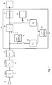
- Noise is received with a microphone 10 and its frequency range is limited by a downstream bandpass filter 11 to a lower frequency range from 5 to 100 Hz.
- a downstream bandpass filter 11 is implemented by a Fast Fourier transformer with an upstream alternating memory in which the digitized, band-limited noise is stored within a time interval of two seconds.
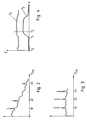
- the Fast Fourier transformer has 1024 frequency cells for equal frequency intervals of 1 ⁇ 2 Hz width and provides a power spectrum of the band-limited noise, which is shown in Fig. 2.
- the power spectrum in FIG. 2 has a background noise spectrum falling from low to high frequencies and three spectral lines at the frequencies 10, 20 and 45 Hz. These three spectral lines come from a distant helicopter, whose main rotor frequency is 10 Hz, the first harmonic at 20 Hz and the tail rotor base frequency at 45 Hz.
- a level comparison circuit 14 arranged downstream of the frequency analyzer 13 is now used to examine whether the energy of the spectral lines has a predetermined frequency width, which is just 0.2 Hz at the frequency 10 Hz, since the main rotor speed typically fluctuates by less than 2% .
- three frequency cells in the range around 10 Hz are compared with one another in terms of their levels. If in the neighboring Frequency cells, i.e. at 91 ⁇ 2 Hz and 101 ⁇ 2 Hz, significantly lower levels than in the frequency cell in between, the spectral line at 10 Hz comes from a helicopter.
- an arrangement 15 is provided in the level comparison circuit 14 for determining mean value level profiles from the power spectrum at the output of the frequency analyzer 13 or an interference spectrum, as described in the published patent application DE-OS 30 35 757.
- the arrangement 15 is followed by a normalization circuit 16, in which the power spectrum is normalized with the interference spectrum at the output of the arrangement 15.
- the normalization circuit 16 consists, for example, of the large dynamic range of its input signals from two logarithmic stages and one differential stage, so that a standardized spectrum is present at the output, the level values of which are logarithmic, as shown in FIG. 3.
- the normalization circuit 16 is followed by a threshold detector 17, in which, depending on an approved false alarm rate, a detection threshold is set with which the standardized spectrum is compared. If one or more spectral levels are above the detection threshold, a helicopter alarm is reported in a downstream detection display 18.
- a first and second arithmetic circuit 20, 21 is provided for forming a first and a second sum. These arithmetic circuits 20, 21 are switchable via an actuatable switch 22.
- the sum S 1 of the spectral level of the power spectrum at the output of the frequency analyzer 13 is formed for each time interval, the course of which is shown over time t in FIG. 4.
- the time t0 to t1 only ambient or noise is received. There is no helicopter noise in the noise.
- the sum S 1 increases slightly and increases until the time t 2.
- the levels of the normalized spectrum at the output of the normalization circuit 16 are summed up per time interval to the sum S2, which is almost 0 in the period from t0 to t1, since no narrow-band spectral lines with the predefinable frequency width are received.
- Broader spectral lines, e.g. B. caused by tanks are leveled in the normalization circuit 16.
- Only the very narrow-band spectral lines of the helicopter are strongly emphasized and thus contribute significantly to the formation of the sum than in the formation of the sum of the non-standardized power spectrum.
- a comparison of the two sums S1 and S2 at time t2 shows that the difference between the two sums S1 and S2 is less than the time between t0 and t1.
- This comparison is carried out in a comparison circuit 23 connected downstream of the computing circuits 20 and 21 and leads to detection or confirmation if the difference between the sums S 1 and S 2 distinguishes a predetermined difference threshold.
- a comparison circuit 23 connected downstream of the computing circuits 20 and 21 and leads to detection or confirmation if the difference between the sums S 1 and S 2 distinguishes a predetermined difference threshold.
- the second sum S2 with a factor is multiplied, taking into account the difference between the sums S1, S2 in the presence of at least one spectral line of a helicopter.
- the sum multiplied by the factor S2 is compared with the sum S1 and provides the detection of the helicopter in the event of equality or exceedance.
Landscapes
- Physics & Mathematics (AREA)
- Mathematical Physics (AREA)
- General Physics & Mathematics (AREA)
- Measurement Of Mechanical Vibrations Or Ultrasonic Waves (AREA)
- Radar Systems Or Details Thereof (AREA)
Applications Claiming Priority (2)
| Application Number | Priority Date | Filing Date | Title |
|---|---|---|---|
| DE4142906 | 1991-12-23 | ||
| DE4142906A DE4142906A1 (de) | 1991-12-23 | 1991-12-23 | Verfahren zum detektieren und unterscheiden weit entfernter hubschrauber von anderen fahrzeugen |
Publications (3)
| Publication Number | Publication Date |
|---|---|
| EP0548689A2 true EP0548689A2 (fr) | 1993-06-30 |
| EP0548689A3 EP0548689A3 (fr) | 1994-04-20 |
| EP0548689B1 EP0548689B1 (fr) | 1997-09-03 |
Family
ID=6448083
Family Applications (1)
| Application Number | Title | Priority Date | Filing Date |
|---|---|---|---|
| EP92121053A Expired - Lifetime EP0548689B1 (fr) | 1991-12-23 | 1992-12-10 | Procédé pour détecter et reconnaître des hélicoptères à grande distance des autres véhicules |
Country Status (2)
| Country | Link |
|---|---|
| EP (1) | EP0548689B1 (fr) |
| DE (2) | DE4142906A1 (fr) |
Cited By (2)
| Publication number | Priority date | Publication date | Assignee | Title |
|---|---|---|---|---|
| DE3734487A1 (de) * | 1987-10-12 | 1989-04-20 | Grs Ges Reaktorsicherheit | Verfahren zur ueberwachung der betriebssicheren arbeitsweise und schadensfrueherkennung komplizierter technischer anlagen |
| WO2006005337A1 (fr) * | 2004-06-11 | 2006-01-19 | Nanonord A/S | Procede d'analyse de frequences fondamentale et application de ce procede |
Families Citing this family (2)
| Publication number | Priority date | Publication date | Assignee | Title |
|---|---|---|---|---|
| DE4317424C2 (de) * | 1993-05-26 | 2002-06-13 | Eads Deutschland Gmbh | Verfahren zur Ermittlung einer periodischen Struktur in einem Linienspektrum und Verwendung eines solchen Verfahrens zur Erkennung und/oder Klassifizierung eines Hubschraubers |
| DE59309579D1 (de) * | 1993-11-24 | 1999-06-17 | Stn Atlas Elektronik Gmbh | Verfahren zum Bestimmen von Grundfrequenzen im Frequenzspektrum einer akustischen Ortungsanlage |
Family Cites Families (2)
| Publication number | Priority date | Publication date | Assignee | Title |
|---|---|---|---|---|
| FR2599860B1 (fr) * | 1984-03-22 | 1989-12-01 | France Etat Armement | Procede et dispositif pour la detection acoustique passive d'aeronefs, notamment d'helicopteres |
| DE3929077C2 (de) * | 1989-09-01 | 1997-01-16 | Matthias Dr Ing Reuter | Verfahren und Einrichtung zur akustischen Identifikation und Klassifikation von Hubschraubern |
-
1991
- 1991-12-23 DE DE4142906A patent/DE4142906A1/de not_active Withdrawn
-
1992
- 1992-12-10 DE DE59208858T patent/DE59208858D1/de not_active Expired - Fee Related
- 1992-12-10 EP EP92121053A patent/EP0548689B1/fr not_active Expired - Lifetime
Cited By (2)
| Publication number | Priority date | Publication date | Assignee | Title |
|---|---|---|---|---|
| DE3734487A1 (de) * | 1987-10-12 | 1989-04-20 | Grs Ges Reaktorsicherheit | Verfahren zur ueberwachung der betriebssicheren arbeitsweise und schadensfrueherkennung komplizierter technischer anlagen |
| WO2006005337A1 (fr) * | 2004-06-11 | 2006-01-19 | Nanonord A/S | Procede d'analyse de frequences fondamentale et application de ce procede |
Also Published As
| Publication number | Publication date |
|---|---|
| EP0548689A3 (fr) | 1994-04-20 |
| DE4142906A1 (de) | 1993-06-24 |
| EP0548689B1 (fr) | 1997-09-03 |
| DE59208858D1 (de) | 1997-10-09 |
Similar Documents
| Publication | Publication Date | Title |
|---|---|---|
| DE69605439T2 (de) | System zum detektieren von mikro-burst | |
| DE69218331T2 (de) | Rauschpegelverringerung in Radargeräten für Streuziele | |
| DE69608667T2 (de) | Wetterradar mit spektraler gauss-einhullenden diskriminierung zum beseitigen von clutter | |
| DE69221995T2 (de) | Radarsystem gegen windscherung mit oberen und unteren höhenwinkel-radarabtastung | |
| DE69127114T2 (de) | Verfahren und Gerät zur Beseitigung von Aliasing in der Doppler-Geschwindigkeit | |
| EP0204295B1 (fr) | Dispositif de mesure de la direction et de la vitesse du vent dans l'atmosphère | |
| DE2928907A1 (de) | Verfahren zur klassifizierung bewegter ziele | |
| DE19705730C2 (de) | Verfahren zur Zielklassifizierung | |
| DE10207465B4 (de) | Verfahren zur Reduzierung der Falschalarmrate in Radarbildern | |
| EP0626583B1 (fr) | Procédé de détermination d'une structure périodique dans un spectre de raies et utilisation dudit procédé | |
| DE3723265C1 (de) | Vorrichtung und Verfahren zur Radarerkennung von Hubschraubern | |
| DE102015200014A1 (de) | Vorrichtung und Verfahren zum Bestimmen einer Eigenschaft eines Objekts | |
| DE3940404A1 (de) | Verfahren und geraet zur dopplereffekt-geschwindigkeitsmessung | |
| DE60225642T2 (de) | Verfahren zur Bestimmung des Azimuts eines Zieles mittels eines ASR-Radars | |
| DE69307551T2 (de) | Doppler wetterradar zum erfassen von windscherungen im flug | |
| DE3233327C2 (de) | Schaltungsanordnung zur Entdeckung und Erkennung von Hubschraubern | |
| DE3929077C2 (de) | Verfahren und Einrichtung zur akustischen Identifikation und Klassifikation von Hubschraubern | |
| DE3744691C2 (de) | Verfahren und Gerät zur Bewertung von Radarzielimpulsen | |
| EP0213541B1 (fr) | Procédé pour détecter des bateaux | |
| EP0548689B1 (fr) | Procédé pour détecter et reconnaître des hélicoptères à grande distance des autres véhicules | |
| DE69232090T2 (de) | Geschwindigkeitsabhängige Empfindlichkeitsreglung | |
| DE2746392C3 (de) | Anordnung zum Schutz vor Störechos | |
| DE3826754C1 (de) | Verfahren zur Zielklassifizierung | |
| EP0947851A2 (fr) | Procédé de classification et/ou identification d'une cible | |
| EP0654676A1 (fr) | Procédé pour déterminer la fréquence fondamentale du spectre de fréquence d'un appareil de localisation acoustique |
Legal Events
| Date | Code | Title | Description |
|---|---|---|---|
| PUAI | Public reference made under article 153(3) epc to a published international application that has entered the european phase |
Free format text: ORIGINAL CODE: 0009012 |
|
| AK | Designated contracting states |
Kind code of ref document: A2 Designated state(s): BE DE FR GB NL SE |
|
| PUAL | Search report despatched |
Free format text: ORIGINAL CODE: 0009013 |
|
| AK | Designated contracting states |
Kind code of ref document: A3 Designated state(s): BE DE FR GB NL SE |
|
| 17P | Request for examination filed |
Effective date: 19940613 |
|
| RAP1 | Party data changed (applicant data changed or rights of an application transferred) |
Owner name: STN ATLAS ELEKTRONIK GMBH |
|
| 17Q | First examination report despatched |
Effective date: 19960819 |
|
| GRAG | Despatch of communication of intention to grant |
Free format text: ORIGINAL CODE: EPIDOS AGRA |
|
| GRAH | Despatch of communication of intention to grant a patent |
Free format text: ORIGINAL CODE: EPIDOS IGRA |
|
| GRAH | Despatch of communication of intention to grant a patent |
Free format text: ORIGINAL CODE: EPIDOS IGRA |
|
| GRAA | (expected) grant |
Free format text: ORIGINAL CODE: 0009210 |
|
| AK | Designated contracting states |
Kind code of ref document: B1 Designated state(s): BE DE FR GB NL SE |
|
| REF | Corresponds to: |
Ref document number: 59208858 Country of ref document: DE Date of ref document: 19971009 |
|
| ET | Fr: translation filed | ||
| GBT | Gb: translation of ep patent filed (gb section 77(6)(a)/1977) |
Effective date: 19971021 |
|
| PGFP | Annual fee paid to national office [announced via postgrant information from national office to epo] |
Ref country code: GB Payment date: 19971112 Year of fee payment: 6 |
|
| PGFP | Annual fee paid to national office [announced via postgrant information from national office to epo] |
Ref country code: SE Payment date: 19971113 Year of fee payment: 6 |
|
| PGFP | Annual fee paid to national office [announced via postgrant information from national office to epo] |
Ref country code: FR Payment date: 19971119 Year of fee payment: 6 |
|
| PGFP | Annual fee paid to national office [announced via postgrant information from national office to epo] |
Ref country code: BE Payment date: 19971210 Year of fee payment: 6 |
|
| PGFP | Annual fee paid to national office [announced via postgrant information from national office to epo] |
Ref country code: NL Payment date: 19971231 Year of fee payment: 6 |
|
| PLBE | No opposition filed within time limit |
Free format text: ORIGINAL CODE: 0009261 |
|
| STAA | Information on the status of an ep patent application or granted ep patent |
Free format text: STATUS: NO OPPOSITION FILED WITHIN TIME LIMIT |
|
| 26N | No opposition filed | ||
| PG25 | Lapsed in a contracting state [announced via postgrant information from national office to epo] |
Ref country code: GB Free format text: LAPSE BECAUSE OF NON-PAYMENT OF DUE FEES Effective date: 19981210 |
|
| PG25 | Lapsed in a contracting state [announced via postgrant information from national office to epo] |
Ref country code: SE Free format text: LAPSE BECAUSE OF NON-PAYMENT OF DUE FEES Effective date: 19981211 |
|
| PG25 | Lapsed in a contracting state [announced via postgrant information from national office to epo] |
Ref country code: BE Free format text: LAPSE BECAUSE OF NON-PAYMENT OF DUE FEES Effective date: 19981231 |
|
| BERE | Be: lapsed |
Owner name: STN ATLAS ELEKTRONIK G.M.B.H. Effective date: 19981231 |
|
| PG25 | Lapsed in a contracting state [announced via postgrant information from national office to epo] |
Ref country code: NL Free format text: LAPSE BECAUSE OF NON-PAYMENT OF DUE FEES Effective date: 19990701 |
|
| GBPC | Gb: european patent ceased through non-payment of renewal fee |
Effective date: 19981210 |
|
| PG25 | Lapsed in a contracting state [announced via postgrant information from national office to epo] |
Ref country code: FR Free format text: LAPSE BECAUSE OF NON-PAYMENT OF DUE FEES Effective date: 19990831 |
|
| NLV4 | Nl: lapsed or anulled due to non-payment of the annual fee |
Effective date: 19990701 |
|
| REG | Reference to a national code |
Ref country code: FR Ref legal event code: ST |
|
| PGFP | Annual fee paid to national office [announced via postgrant information from national office to epo] |
Ref country code: DE Payment date: 20001201 Year of fee payment: 9 |
|
| PG25 | Lapsed in a contracting state [announced via postgrant information from national office to epo] |
Ref country code: DE Free format text: LAPSE BECAUSE OF NON-PAYMENT OF DUE FEES Effective date: 20020702 |