EP0548691B1 - Système d'encadrement pour enseignes - Google Patents
Système d'encadrement pour enseignes Download PDFInfo
- Publication number
- EP0548691B1 EP0548691B1 EP92121068A EP92121068A EP0548691B1 EP 0548691 B1 EP0548691 B1 EP 0548691B1 EP 92121068 A EP92121068 A EP 92121068A EP 92121068 A EP92121068 A EP 92121068A EP 0548691 B1 EP0548691 B1 EP 0548691B1
- Authority
- EP
- European Patent Office
- Prior art keywords
- sign
- tensional
- slot
- devices
- flexible
- Prior art date
- Legal status (The legal status is an assumption and is not a legal conclusion. Google has not performed a legal analysis and makes no representation as to the accuracy of the status listed.)
- Expired - Lifetime
Links
- 238000009432 framing Methods 0.000 title abstract description 20
- 239000000463 material Substances 0.000 claims abstract description 64
- 238000012423 maintenance Methods 0.000 claims abstract description 7
- 230000013011 mating Effects 0.000 claims abstract description 5
- 239000003351 stiffener Substances 0.000 claims description 6
- 238000005452 bending Methods 0.000 claims description 2
- 238000005286 illumination Methods 0.000 claims 1
- 238000000034 method Methods 0.000 abstract 1
- 238000001125 extrusion Methods 0.000 description 42
- 238000009434 installation Methods 0.000 description 9
- 239000002184 metal Substances 0.000 description 9
- 238000005304 joining Methods 0.000 description 8
- 239000012769 display material Substances 0.000 description 3
- 238000005096 rolling process Methods 0.000 description 3
- XLYOFNOQVPJJNP-UHFFFAOYSA-N water Substances O XLYOFNOQVPJJNP-UHFFFAOYSA-N 0.000 description 3
- 230000000717 retained effect Effects 0.000 description 2
- 238000009958 sewing Methods 0.000 description 2
- 230000032683 aging Effects 0.000 description 1
- 239000004020 conductor Substances 0.000 description 1
- 230000001419 dependent effect Effects 0.000 description 1
- 238000009826 distribution Methods 0.000 description 1
- 230000005484 gravity Effects 0.000 description 1
- 238000004519 manufacturing process Methods 0.000 description 1
- 230000002787 reinforcement Effects 0.000 description 1
- 238000007665 sagging Methods 0.000 description 1
- 238000009966 trimming Methods 0.000 description 1
Images







Classifications
-
- G—PHYSICS
- G09—EDUCATION; CRYPTOGRAPHY; DISPLAY; ADVERTISING; SEALS
- G09F—DISPLAYING; ADVERTISING; SIGNS; LABELS OR NAME-PLATES; SEALS
- G09F15/00—Boards, hoardings, pillars, or like structures for notices, placards, posters, or the like
- G09F15/0006—Boards, hoardings, pillars, or like structures for notices, placards, posters, or the like planar structures comprising one or more panels
- G09F15/0025—Boards, hoardings, pillars, or like structures for notices, placards, posters, or the like planar structures comprising one or more panels display surface tensioning means
Definitions
- This invention relates to a FRAMING SYSTEM FOR SIGNS having a sheet of flexible sign material stretched across the opening of a frame.
- adjustable clips having a series of serrations on one of its sides, which mates with an identical series of serrations on the edge of the sign.
- the adjustment of the tension of the flexible face material is done using special pliers to engage the clips onto few or several serrations.
- the EP-A-0 114 453 discloses an illuminated sign having a housing closed by a translucent flexible sheet of display material being stretched across frame members of said housing.
- the flexible sheet is wrapped around bars which are held in slots at a predefined position inside a support element.
- the support elements are fixed on the frame members by means of several bolts which project in a slot with thread forming serrations.
- the frame members are held and stiffed by braces connected lengthwise by a tube being arranged between the light source and the translucent sheet of display material.
- the disclosed sign is closed on the top and on the bottom by an upper and a lower extruded side panel engaging in the frame members and being sealed by elastomeric seals, the engagement being generated by a pivotal movement provided only by gravity. In order to allow this pivotal movement and the consequent engagement of the side panels with the frame members, the disclosed frame members have different shapes.
- a similar sign is disclosed in CA-A-1 172 448.
- the tensioning or stretching of the translucent sheet has to be performed by screwing in several different bolts with a screw driver, said bolts fixing progressively a support element to the sign's frame members, the support element containing a bar around which the translucent sheet is wrapped.
- a subsequent re-opening of the sign involves the corresponding steps in inverted order.
- the tensioning as well as a subsequent opening prove to be therefore complicated and time expensive. Furthermore, the disclosed sign contains a multitude of different elements, which increase the production costs.
- the tensional devices can be installed in particular by hand along the edge of the face material, the face material not requiring accurate dimensions, marking or sewing of pockets along its edges.
- the stretching of the flexible sign material is done by pushing the tensional devices into a slot along the opening of the sign's frame. The push is done in particular by hand, with or without the use of a slot type blade screw-driver or of other tools.
- the sign has its sides made in one piece, thus preventing leakage of water or moisture inside the sign's casing.
- the sign framing system has a corner cap, which is installed manually without fasteners. The cap is installed by engaging its rear portion into a retaining lip and by twisting it in its final position causing a set of mating lips to engage and retain it in place.
- the framing system according to this invention can be re-opened for maintenance with minimum tooling.
- the framing system comprises a corner cap, which is removed by twisting it manually inward along its length.
- the tensional devices are removed by prying with a slot type screw-driver to disengage its embossments from the frame's serrations.
- the framing system comprises a rigid extrusion covering the periphery of the sign, and a sheet of metal covering the rear opening of the frame.
- a series of C-frames are attached to the sign support structure with screws through the backing skin of the sign.
- the C-frames are attached at regular spacings inside the sign casing, to the side extrusions using screws driven from the inside of the sign casing.
- the C-frames provide the rigidity and the accuracy of location for the side extrusions.
- Each side extrusion has a slot at its edge along the front opening of the sign.
- the slot has a series of serrations on one of its inside face to engage with embossments on the tensional devices.
- the serrations provide adjustment in the location of the tensional devices and thus provide adjustment in the tension of the flexible face material.
- the tensional devices are closed on the edge of a pre-cut flexible sign material by hand.
- the closing of the devices pushes two prongs protruding from one of its side through the flexible sign material and through two mating holes on its other side.
- the tensional devices can be re-positioned. This is done by trimming off with scissors a portion at the edge of the flexible face material, and by relocating the tensional devices.
- the framing system described can be built on the job site using modular components. It can also be delivered as pre-fabricated sections and hoisted in place.
- the flexible face material used for this invention is pre-painted, and delivered to the installation site in a rolled-up form.
- the roll of flexible face material is unwounded on a reel which rolls along the sign frame, supported by trolley wheels rolling on the upper extrusion.
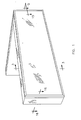
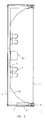
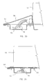
- the new framing system illustrated on figures no. 1, no. 2, and no. 3 comprises a flexible face material 1 which is supported by tensional devices 2.
- the tensional devices are adjusted into a metal extrusions 3 around the periphery of the sign.
- the framing system also comprises a backing sheet of metal 4 and a series of C-frames 5 spaced equally and bolted to the sign support structure using fasters driven from the inside of the casing, and through the backing sheet 4.
- the sign is illuminated by light fixture 6 mounted in tandem and overlapping at each end. The light is reflected toward the edges of the sign on reflectors 61 installed at the top and bottom of the sign.
- the tensional devices 2 and the edge of the extrusion is covered by a corner cap 8.
- the extrusion 3 is positioned on the C-frame 5 using locating lips 12, 13 and 14.
- the extrusion 3 is retained to the C-frame 5 with a screw 16 driven from the inside of the casing through lip 12.
- the lip 14 forms a cavity 15 to mate with the edge of the backing sheet 4.
- the extrusion 3 is attached to the backing sheet 4 using screws 17 or rivets through lip 18 of the extrusion.
- the extrusion 3 is made in one piece to prevent leakage of water or moisture inside the sign's casing.
- the extrusion 3 has a slot 10 at the edge facing the front of the sign.
- the outside wall of this slot 10 has a series of serrations 11 to mate with embossments on the tensional device 2.
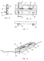
- the tensional device 2 is made of two halves with a thin section 19 along the centre line of its long axis.
- One half has two prongs 20 protruding from its surface.
- the other half has two tapered holes 21 to mate with the prongs 20 when the device is bent fully along the thin section 19.
- Each prong 20 has a pointed end and a recess in its diameter below the point. This recess forms a sharp edge 22 which is slightly wider than the small diameter of the taper hole 21.
- the tensional device 2 is installed on the flexible face material 1 by bending the device 2 manually along its thin edge 19, over the edge of the face material.
- the two prongs 20 will puncture through the face material 1.
- the sharp edge 22 locks through the taper holes 21 to keep the device 2 closed over the face material.
- the tensional device has two shallow slots 23 on its edge near the prongs.
- the provision for the slots 23 is to pry the device open with a slot type blade screw-driver, for repositioning it to a new location.
- the tensional device 2 has two sets of sharp embossments 24 to engage in the serrations 11 of the extrusion 3.
- the tensional device 2 has a recess 25 between the embossments 24. This recess is used to pry the devices out of the serrations 11 using a slot type blade screw-driver.
- the tensional device has another embossment 26 over its entire length.
- This embossment acts as a pivot point when the tensional device is pushed over the serrations 11 inside the slot 10, as it can be seen of the figure no. 9.
- the embossment 26 gives leverage to the tensional device 2 and forces it to rotate and to apply more pressure toward the serrations 11 when a tension is applied on the flexible face material.
- the rib 27 on the extrusion 3 adds stiffness to the inside wall of the slot 10. The rib prevents excessive sagging between the supports 5, under the load applied by the flexible face material.
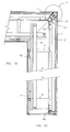
- the cap 8 is installed on the extrusion 3 by clipping it in place.
- the lip 28 on the cap 8 is engaged with the lip 29 of the extrusion 3.
- the cap is pivoted towards the front of the sign until the lip 30 on the cap 8 slides over and clips on lip 31 on the extrusion 3.
- the cap 8 is prevented to disengage from the locked position by lip 32 which comes in contact with the flexible material, before the lip 28 releases from lip 29.
- the removal of the cap 8 for maintenance purposes is done by forcing this lip 32 against the flexible face material 1 as it can be seen on the figure no. 13.
- the lips 30 and 31 can slide into one another until lip 28 disengaged from lip 29.
- the removal of the cap 8 is done manually by twisting it towards the inside of the sign's frame.
- a wider cap 9 can also be used.
- the joining of two sections of caps is done with a piece of flat metal 36 caps which fits precisely between lips 33 and 34 inside the face of the caps. This is illustrated on figure no. 10, and figure no. 21.
- a conventional sign may be refitted with the new framing system using the extrusion no. 37.
- the installation of this extrusion over an existing sign is done with screws through the tongue 38, and into the existing frame.
- the reinforcement of this extrusion at the joints is done with a flat piece of metal between grooves 39 and 40, which overlaps the two sections.
- the tensional block 2 can be removed from the slot 10 by prying with a slot type screw-driver blade 41 between the serrations 11 and the devices 2, to force the embossments 24 out of the serrations 11.
- the removal of the device is completed by pushing in the flexible face material 1 to increase its tension and pull the device out of the slot 10, as it can be seen on Figure no. 14.
- the Figure no. 15 illustrates the overlapping of the light tubes 6 at corners and it illustrates the location of the wiring trays 42.
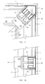
- the Figure no. 15 illustrates also the components used to stretch the face material 1 longitudinally at corners.
- the flexible face material 1 is cut at corners.
- a special extrusion 43 having two slots 10 side by side and two series of serrations 11 is used to retain two series of tensional devices 2, each set holding to one edge of the flexible face material. An enlarged view of this is shown on Figure no. 17.
- the same extrusion 43 is used to make joints in the flexible face material 1 as shown on Figure 18.
- the extrusion 43 is attached to the framing extrusion 3 with clip angles 47 and screws, at each of its extremities.
- the slots 10 and the tensional devices 2 in the extrusion 43 are covered with a corner cap 44 at corners and with a flat cap 45 at joints. Both caps have legs 46 which can flex to fit between the extrusion 43 and the tensional device 2. The deflection of the legs 46 causes the legs to apply an outward pressure against the opening of the slot 10. This pressure together with the squeezing force of the tensional device over the leg 46 keep the cap in place.
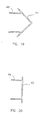
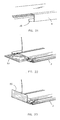
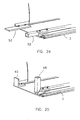
- FIG. 15 Several ways of joining the extrusions 3 at corners is illustrated on Figures no. 15, 16, 22, 23, 24, and 25.
- a variety of combinations of stiffeners can be used. Vertical corners can be joined using corner tubing 48, clip angles 49 and full width angles 50. Horizontal corners and horizontal joints can be made with joining plates 51, straight tubing 52, and flat bar 53. In all cases these stiffeners are attached to the extrusions 3 and 43 using screws.
- the light fixture casings 7 can be used as a single string of lamp tubes in a narrow sign.
- the light fixture sings 7 can be grouped two or more together with connection trays 42, to accommodate for wider signs.
- the light sockets 54 are wired with electrical conductors 56 passing through the fixture casing 7 to the ballast 55.
- the wiring connections for the electrical supply to a light fixture module, or in between adjoining light fixture modules, are done in a connection tray 42.
- the tray 42 is normally covered by the adjoining light fixture module. Otherwise, and in cases where the width of the fixture casing 7 is not sufficient to cover the tray 42, sheet metal covers are used to cover the tray entirely.
- the Figure no. 30 illustrates a sheet metal cover 58, which is used with a ballast 57 having its wiring 56 coming out from the end.
- the Figure no. 31 illustrates a sheet metal cover 59 which is used with a ballast 55 having its wiring 56 coming out from the bottom. Both types of covers 58 and 59 are attached to the connections trays 42 with screws 60.
- the light tubes 6 and light fixtures 7 are installed on the frame members 5 near the centre line of the sign.
- the reflectors 61 send an even distribution of light to the outer edges of the sign.
- the reflectors 61 are installed on the frame member 5 with screws.
- the Figures no. 33, 34 and 35 illustrate one of many possible ways to install the flexible face material 1.
- the flexible face material is delivered to the installation site in a rolled up form.
- a reel plate 62 and reel axle 63 are used to unwind the roll of flexible sign material 1.
- the reel assembly is supported by trolley wheels 64 which roll on the top extrusion 3.
- the weight of the reel assembly is counter balanced with a set of horizontal wheels 66 rolling against the nosing of the lower extrusions 3.
- Additional trolley wheels 65 lock the reel assembly in place.
- These wheels 65 are free to slide up and down in slots 67. These are held in the upper position, against the lower face of extrusion 3 and behind lip 27, by the latch blade 68.
- the latch blade 68 pivots on the axle of the trolley wheel 64.
- the latch blades 68 are used to secure the reel in place on the sign frame or to remove it after completion of the face material installation.
- the reel assembly is adjustable to different height of signs. Its central support member 69 is made of two hollow sections sliding into one another. A bolt 70 through a combination of holes in the support member 69 is used to adjust the height of the reel assembly.
Landscapes
- Physics & Mathematics (AREA)
- General Physics & Mathematics (AREA)
- Engineering & Computer Science (AREA)
- Theoretical Computer Science (AREA)
- Road Signs Or Road Markings (AREA)
- Communication Control (AREA)
- Non-Portable Lighting Devices Or Systems Thereof (AREA)
- Circuits Of Receivers In General (AREA)
- Aiming, Guidance, Guns With A Light Source, Armor, Camouflage, And Targets (AREA)
- Manufacture, Treatment Of Glass Fibers (AREA)
- Mirrors, Picture Frames, Photograph Stands, And Related Fastening Devices (AREA)
Claims (7)
- Enseigne dont le matériau de face (1) est tendu au moyen de dispositifs de tension (2) installés à intervalles réguliers sur les bords du matériau de face (1), lesdits dispositifs de tension (2) possédant des bosselures d'enclenchement (24) pour s'enclencher sur une série de dentelures (11) à l'intérieur d'une encoche (10) faisant face à l'extérieur le long du bord extérieur de l'encadrement de l'enseigne, dans lequel lesdits dispositifs de tension (2) forment des blocs de tension ayant des dimensions qui leur permettent d'être logés à l'intérieur de ladite rainure (10) et d'être tournés suivant leur axe longitudinal, lesdites bosselures (24) glissant sur lesdites dentelures (11) lorsque lesdits dispositifs de tension sont poussés dans ladite rainure (10) et lesdites bosselures (24) fixant les dispositifs de tension (2) en place lorsqu'une tension est appliquée extérieurement par le matériau de face.
- Enseigne selon la revendication 1 ayant des dispositifs de tension (2) qui sont installés manuellement sur les bords du matériau d'enseigne souple (1) en pliant chaque dispositif (2) suivant une partie amincie (19) sur sa ligne médiane sur le matériau d'enseigne (1), en poussant deux broches pointues (20) faisant saillie de l'une de ses moitiés à travers le matériau d'enseigne souple (1) et dans des orifices d'accouplement (21) de sa deuxième moitié, ladite broche (20) ayant un renfoncement dans son diamètre de telle sorte que le bord de ce renfoncement se verrouille dans l'orifice d'accouplement (21) en maintenant le dispositif de tension (2) fermé sur le matériau d'enseigne (1).
- Enseigne selon l'une quelconque des revendications précédentes ayant des dispositif de tension (2) qui peuvent être retirés pour l'entretien des composants de l'enseigne en enfonçant un tournevis du type à fente (14) ou un objet plat similaire entre les bosselures (24) du dispositif de tension (2) et les dentelures (11) dans une encoche (25) le long du pourtour de l'ouverture de l'encadrement d'enseigne.
- Enseigne selon l'une quelconque des revendications précédentes ayant un couvercle (8, 9) recouvrant les dispositif de tension (2) et la rainure (10) le long du pourtour de l'enseigne, qui peut être installé en le fixant en place manuellement, et qui peut être enlevé pour l'entretien des composants de l'enseigne en le tordant manuellement vers l'intérieur de l'enseigne, dans l'axe suivant sa longueur.
- Enseigne selon l'une quelconque des revendications précédentes ayant ses côtés entièrement recouverts par une partie (3) extrudée continue.
- Enseigne selon l'une quelconque des revendications précédentes ayant une illumination sans ombre du fait de l'absence de raidisseurs d'encadrement entre les lampes (6) et le matériau de face (1).
- Enseigne selon l'une quelconque des revendications précédentes dans laquelle lesdits dispositifs de tension (2) comprennent de plus une bosselure de pivotement (26) qui fixe ensemble avec les bosselures d'enclenchement (24) les dispositifs de tension (2) lorsqu'ils sont glissés dans la rainure (10).
Applications Claiming Priority (2)
| Application Number | Priority Date | Filing Date | Title |
|---|---|---|---|
| US07/805,680 US5255459A (en) | 1991-12-12 | 1991-12-12 | Framing system for signs |
| US805680 | 1991-12-12 |
Publications (2)
| Publication Number | Publication Date |
|---|---|
| EP0548691A1 EP0548691A1 (fr) | 1993-06-30 |
| EP0548691B1 true EP0548691B1 (fr) | 1996-03-20 |
Family
ID=25192220
Family Applications (1)
| Application Number | Title | Priority Date | Filing Date |
|---|---|---|---|
| EP92121068A Expired - Lifetime EP0548691B1 (fr) | 1991-12-12 | 1992-12-10 | Système d'encadrement pour enseignes |
Country Status (6)
| Country | Link |
|---|---|
| US (1) | US5255459A (fr) |
| EP (1) | EP0548691B1 (fr) |
| AT (1) | ATE135841T1 (fr) |
| DE (1) | DE69209255T2 (fr) |
| DK (1) | DK0548691T3 (fr) |
| ES (1) | ES2087416T3 (fr) |
Cited By (3)
| Publication number | Priority date | Publication date | Assignee | Title |
|---|---|---|---|---|
| DE202008009183U1 (de) | 2008-01-29 | 2008-11-06 | Eps Profiled Solutions Gmbh | Fassadenelement |
| DE202009012638U1 (de) | 2009-03-23 | 2009-12-17 | Eps Profiled Solutions Gmbh | Halteprofil, Spannvorrichtung und Fassadenelement |
| DE102004052367B4 (de) * | 2004-06-29 | 2010-12-02 | Ellermann, Margarete | Verkleidungselement für eine Wand- und/oder eine Decke |
Families Citing this family (22)
| Publication number | Priority date | Publication date | Assignee | Title |
|---|---|---|---|---|
| US5398388A (en) * | 1993-05-07 | 1995-03-21 | Coleman; Kelly R. | Tensioning assembly for flexible sign faces and awnings |
| EP0801780A1 (fr) * | 1993-05-07 | 1997-10-22 | COLEMAN, Kelly R. | Structure de cadre avec profile en c, pour panneaux d'affichage |
| SE503745C2 (sv) * | 1994-08-29 | 1996-08-19 | Goeran Johansson | Skylt med spännanordning för dukyta |
| US5570525A (en) * | 1995-01-06 | 1996-11-05 | Signstrut, Ltd. | Flexible face sign with uniform luminosity |
| US5669166A (en) * | 1995-10-06 | 1997-09-23 | Verret; Normand | Casing for sign |
| US6073376A (en) * | 1998-08-24 | 2000-06-13 | Verret; Normand | Edging for sign casing |
| US6061941A (en) * | 1998-08-25 | 2000-05-16 | Verret; Normand | Flex holder for flexible face sign |
| US6370802B1 (en) | 1999-09-16 | 2002-04-16 | Lsi Industries Inc | Back-lit fascia with spring loaded fascia tensioner |
| AU2001252092A1 (en) * | 2000-05-18 | 2001-12-03 | Bieri Blachen Ag | Device for stretching foil material and poster holder built with said device |
| DE10194976D2 (de) * | 2000-11-20 | 2003-10-30 | Manfred Kluth | Beleuchtungselement |
| US6637080B2 (en) | 2001-07-09 | 2003-10-28 | Normand Verret | Reversible flex holder for flexible face sign |
| US7159349B2 (en) * | 2002-01-15 | 2007-01-09 | Sign Media Systems, Inc. | Sign and awning attachment system and method of use |
| US7200962B2 (en) * | 2004-03-16 | 2007-04-10 | Keyser Industries, Inc. | Flexible, frameless display module, device and method |
| KR100636701B1 (ko) * | 2004-10-25 | 2006-10-23 | 박재길 | 광고판용 램프 지지장치 |
| WO2009095200A1 (fr) * | 2008-01-29 | 2009-08-06 | Eps Profiled Solutions Gmbh | Elément de façade doté d’un élément de surface flexible |
| US8595966B2 (en) | 2010-10-12 | 2013-12-03 | Signcomp, Llc | Sign assembly |
| CA2846355C (fr) | 2013-03-15 | 2016-10-04 | Signcomp, Llc | Ensemble enseigne |
| US9633583B2 (en) * | 2015-06-25 | 2017-04-25 | Apco Graphics, Inc. | Low profile, self-aligning customizable sign and method of displaying customizable information |
| JP5967740B1 (ja) * | 2015-07-30 | 2016-08-10 | 株式会社リディアワークス | シートの展張装置 |
| US10260229B2 (en) * | 2017-04-12 | 2019-04-16 | Southern Comfort Shelters, Inc. | Blast resistant shelter and method of assembly |
| FR3078812B1 (fr) * | 2018-03-07 | 2021-03-19 | Clipso Productions | Procede de montage d'un revetement souple tendu sur un cadre de fixation et cadre de fixation pour la mise en oeuvre dudit procede |
| US12272270B2 (en) | 2022-03-09 | 2025-04-08 | Gestion Verret, Inc | One-piece reversible flex holder with calibrated retention, for flexible face signs and tarp buildings |
Family Cites Families (6)
| Publication number | Priority date | Publication date | Assignee | Title |
|---|---|---|---|---|
| US2915844A (en) * | 1956-11-01 | 1959-12-08 | Prism Signs Inc | Shallow scintillating sign |
| US4547987A (en) * | 1983-01-18 | 1985-10-22 | Johann Stilling | Sign structure |
| DE3378553D1 (en) | 1983-01-25 | 1988-12-29 | Signtech Inc | Illuminated signs |
| CA1172448A (fr) | 1983-10-11 | 1984-08-14 | Signtech Inc. | Enseigne |
| US4937961A (en) * | 1989-03-09 | 1990-07-03 | Signtech, Inc. | Sign assembly |
| US4955928A (en) * | 1989-04-18 | 1990-09-11 | Signstrut, Ltd. | Tensioning connector for retaining sign membranes |
-
1991
- 1991-12-12 US US07/805,680 patent/US5255459A/en not_active Expired - Lifetime
-
1992
- 1992-12-10 ES ES92121068T patent/ES2087416T3/es not_active Expired - Lifetime
- 1992-12-10 AT AT92121068T patent/ATE135841T1/de not_active IP Right Cessation
- 1992-12-10 DK DK92121068.8T patent/DK0548691T3/da active
- 1992-12-10 EP EP92121068A patent/EP0548691B1/fr not_active Expired - Lifetime
- 1992-12-10 DE DE69209255T patent/DE69209255T2/de not_active Expired - Lifetime
Cited By (3)
| Publication number | Priority date | Publication date | Assignee | Title |
|---|---|---|---|---|
| DE102004052367B4 (de) * | 2004-06-29 | 2010-12-02 | Ellermann, Margarete | Verkleidungselement für eine Wand- und/oder eine Decke |
| DE202008009183U1 (de) | 2008-01-29 | 2008-11-06 | Eps Profiled Solutions Gmbh | Fassadenelement |
| DE202009012638U1 (de) | 2009-03-23 | 2009-12-17 | Eps Profiled Solutions Gmbh | Halteprofil, Spannvorrichtung und Fassadenelement |
Also Published As
| Publication number | Publication date |
|---|---|
| ATE135841T1 (de) | 1996-04-15 |
| ES2087416T3 (es) | 1996-07-16 |
| DE69209255T2 (de) | 1996-11-28 |
| US5255459A (en) | 1993-10-26 |
| DE69209255D1 (de) | 1996-04-25 |
| EP0548691A1 (fr) | 1993-06-30 |
| DK0548691T3 (da) | 1996-08-05 |
Similar Documents
| Publication | Publication Date | Title |
|---|---|---|
| EP0548691B1 (fr) | Système d'encadrement pour enseignes | |
| US7818906B2 (en) | Lightbox | |
| US5020254A (en) | Illuminated sign system having tensioning means | |
| US4692847A (en) | Illuminated awning assembly | |
| US5467546A (en) | Tensioned fabric sign | |
| WO1995020207A1 (fr) | Systeme de montage d'affiche sur un poteau | |
| AU671720B2 (en) | Illuminated canopy system | |
| CA2948941C (fr) | Panneau transportable | |
| FI86488B (fi) | Faestanordning foer faestning av skivor, saerskilt ljusreklamskivor. | |
| US4516343A (en) | Sign structure | |
| EP0114453B1 (fr) | Panneaux de signalisation éclairés | |
| US4833805A (en) | Display signs | |
| US2775833A (en) | Signboard structure | |
| CA2057569C (fr) | Cadres pour enseignes | |
| WO1997050073A1 (fr) | Element d'encadrement utilise dans l'assemblage d'une enseigne | |
| US20060059741A1 (en) | Illuminated foldable module and display system | |
| GB2069738A (en) | Signs | |
| WO1993012514A1 (fr) | Panneau publicitaire | |
| US20060162202A1 (en) | Illuminated foldable module and display system | |
| CA1172448A (fr) | Enseigne | |
| JP2005114779A (ja) | 電飾広告塔の帆布製表示パネル | |
| IES70918B2 (en) | A display sign | |
| EP0114454A1 (fr) | Dispositif d'affichage illuminé | |
| CA2202077A1 (fr) | Enseigne illuminee sur bordure de toiture | |
| CA2025462A1 (fr) | Chassis pour marquises et grandes enseignes |
Legal Events
| Date | Code | Title | Description |
|---|---|---|---|
| PUAI | Public reference made under article 153(3) epc to a published international application that has entered the european phase |
Free format text: ORIGINAL CODE: 0009012 |
|
| AK | Designated contracting states |
Kind code of ref document: A1 Designated state(s): AT BE CH DE DK ES FR GB GR IE IT LI LU MC NL PT SE |
|
| 17P | Request for examination filed |
Effective date: 19930726 |
|
| 17Q | First examination report despatched |
Effective date: 19940429 |
|
| GRAA | (expected) grant |
Free format text: ORIGINAL CODE: 0009210 |
|
| AK | Designated contracting states |
Kind code of ref document: B1 Designated state(s): AT BE CH DE DK ES FR GB GR IE IT LI LU MC NL PT SE |
|
| PG25 | Lapsed in a contracting state [announced via postgrant information from national office to epo] |
Ref country code: GR Free format text: LAPSE BECAUSE OF FAILURE TO SUBMIT A TRANSLATION OF THE DESCRIPTION OR TO PAY THE FEE WITHIN THE PRESCRIBED TIME-LIMIT Effective date: 19960320 |
|
| REF | Corresponds to: |
Ref document number: 135841 Country of ref document: AT Date of ref document: 19960415 Kind code of ref document: T |
|
| REG | Reference to a national code |
Ref country code: IE Ref legal event code: FG4D Free format text: 67673 |
|
| REF | Corresponds to: |
Ref document number: 69209255 Country of ref document: DE Date of ref document: 19960425 |
|
| ET | Fr: translation filed | ||
| ITF | It: translation for a ep patent filed | ||
| REG | Reference to a national code |
Ref country code: ES Ref legal event code: BA2A Ref document number: 2087416 Country of ref document: ES Kind code of ref document: T3 |
|
| PG25 | Lapsed in a contracting state [announced via postgrant information from national office to epo] |
Ref country code: PT Effective date: 19960620 |
|
| REG | Reference to a national code |
Ref country code: CH Ref legal event code: NV Representative=s name: SCHAAD, BALASS & PARTNER AG |
|
| REG | Reference to a national code |
Ref country code: ES Ref legal event code: FG2A Ref document number: 2087416 Country of ref document: ES Kind code of ref document: T3 |
|
| REG | Reference to a national code |
Ref country code: DK Ref legal event code: T3 |
|
| PG25 | Lapsed in a contracting state [announced via postgrant information from national office to epo] |
Ref country code: IE Free format text: LAPSE BECAUSE OF NON-PAYMENT OF DUE FEES Effective date: 19961210 |
|
| PLBE | No opposition filed within time limit |
Free format text: ORIGINAL CODE: 0009261 |
|
| STAA | Information on the status of an ep patent application or granted ep patent |
Free format text: STATUS: NO OPPOSITION FILED WITHIN TIME LIMIT |
|
| 26N | No opposition filed | ||
| PG25 | Lapsed in a contracting state [announced via postgrant information from national office to epo] |
Ref country code: MC Effective date: 19970630 |
|
| PGFP | Annual fee paid to national office [announced via postgrant information from national office to epo] |
Ref country code: AT Payment date: 20010221 Year of fee payment: 9 |
|
| REG | Reference to a national code |
Ref country code: GB Ref legal event code: IF02 |
|
| PGFP | Annual fee paid to national office [announced via postgrant information from national office to epo] |
Ref country code: LU Payment date: 20020107 Year of fee payment: 10 |
|
| PGFP | Annual fee paid to national office [announced via postgrant information from national office to epo] |
Ref country code: NL Payment date: 20020117 Year of fee payment: 10 |
|
| PG25 | Lapsed in a contracting state [announced via postgrant information from national office to epo] |
Ref country code: LU Free format text: LAPSE BECAUSE OF NON-PAYMENT OF DUE FEES Effective date: 20021210 Ref country code: AT Free format text: LAPSE BECAUSE OF NON-PAYMENT OF DUE FEES Effective date: 20021210 |
|
| PG25 | Lapsed in a contracting state [announced via postgrant information from national office to epo] |
Ref country code: NL Free format text: LAPSE BECAUSE OF NON-PAYMENT OF DUE FEES Effective date: 20030701 |
|
| NLV4 | Nl: lapsed or anulled due to non-payment of the annual fee |
Effective date: 20030701 |
|
| REG | Reference to a national code |
Ref country code: ES Ref legal event code: GD2A Effective date: 20040709 |
|
| BECA | Be: change of holder's address |
Owner name: *SIGNCOMP LLC2925-A WALKEN CT. GRAND RAPIDS, MICHI Effective date: 20041213 |
|
| REG | Reference to a national code |
Ref country code: CH Ref legal event code: NV Representative=s name: PATENTANWAELTE SCHAAD, BALASS, MENZL & PARTNER AG Ref country code: CH Ref legal event code: PUE Owner name: SIGNCOMP, LLC Free format text: ALUMIFLEX INC.#823 RUE CANADA#EDMUNDSTON, NEW BRUNSWICK E3V 3X7 (CA) -TRANSFER TO- SIGNCOMP, LLC#2925-A WALKENT CT.#GRAND RAPIDS, MICHIGAN 49544 (US) |
|
| REG | Reference to a national code |
Ref country code: GB Ref legal event code: 732E |
|
| REG | Reference to a national code |
Ref country code: FR Ref legal event code: TP |
|
| REG | Reference to a national code |
Ref country code: ES Ref legal event code: PC2A |
|
| PGFP | Annual fee paid to national office [announced via postgrant information from national office to epo] |
Ref country code: GB Payment date: 20101123 Year of fee payment: 19 |
|
| PGFP | Annual fee paid to national office [announced via postgrant information from national office to epo] |
Ref country code: CH Payment date: 20111026 Year of fee payment: 20 Ref country code: SE Payment date: 20111207 Year of fee payment: 20 Ref country code: FR Payment date: 20111205 Year of fee payment: 20 Ref country code: ES Payment date: 20111220 Year of fee payment: 20 Ref country code: DK Payment date: 20111124 Year of fee payment: 20 |
|
| PGFP | Annual fee paid to national office [announced via postgrant information from national office to epo] |
Ref country code: DE Payment date: 20111230 Year of fee payment: 20 |
|
| PGFP | Annual fee paid to national office [announced via postgrant information from national office to epo] |
Ref country code: BE Payment date: 20120103 Year of fee payment: 20 Ref country code: IT Payment date: 20111228 Year of fee payment: 20 |
|
| REG | Reference to a national code |
Ref country code: DE Ref legal event code: R071 Ref document number: 69209255 Country of ref document: DE |
|
| REG | Reference to a national code |
Ref country code: DE Ref legal event code: R071 Ref document number: 69209255 Country of ref document: DE |
|
| BE20 | Be: patent expired |
Owner name: *SIGNCOMP LLC Effective date: 20121210 |
|
| REG | Reference to a national code |
Ref country code: CH Ref legal event code: PL |
|
| REG | Reference to a national code |
Ref country code: GB Ref legal event code: PE20 Expiry date: 20121209 Ref country code: DK Ref legal event code: EUP |
|
| REG | Reference to a national code |
Ref country code: SE Ref legal event code: EUG |
|
| PG25 | Lapsed in a contracting state [announced via postgrant information from national office to epo] |
Ref country code: GB Free format text: LAPSE BECAUSE OF EXPIRATION OF PROTECTION Effective date: 20121209 |
|
| REG | Reference to a national code |
Ref country code: ES Ref legal event code: FD2A Effective date: 20140827 |
|
| PG25 | Lapsed in a contracting state [announced via postgrant information from national office to epo] |
Ref country code: ES Free format text: LAPSE BECAUSE OF EXPIRATION OF PROTECTION Effective date: 20121211 |