EP0548724B1 - Procédé de fabrication d'aubes de turbine ou de compresseur - Google Patents
Procédé de fabrication d'aubes de turbine ou de compresseur Download PDFInfo
- Publication number
- EP0548724B1 EP0548724B1 EP92121233A EP92121233A EP0548724B1 EP 0548724 B1 EP0548724 B1 EP 0548724B1 EP 92121233 A EP92121233 A EP 92121233A EP 92121233 A EP92121233 A EP 92121233A EP 0548724 B1 EP0548724 B1 EP 0548724B1
- Authority
- EP
- European Patent Office
- Prior art keywords
- blades
- rotor
- fixture
- axially
- ring
- Prior art date
- Legal status (The legal status is an assumption and is not a legal conclusion. Google has not performed a legal analysis and makes no representation as to the accuracy of the status listed.)
- Expired - Lifetime
Links
Images

Classifications
-
- B—PERFORMING OPERATIONS; TRANSPORTING
- B23—MACHINE TOOLS; METAL-WORKING NOT OTHERWISE PROVIDED FOR
- B23B—TURNING; BORING
- B23B1/00—Methods for turning or working essentially requiring the use of turning-machines; Use of auxiliary equipment in connection with such methods
-
- F—MECHANICAL ENGINEERING; LIGHTING; HEATING; WEAPONS; BLASTING
- F01—MACHINES OR ENGINES IN GENERAL; ENGINE PLANTS IN GENERAL; STEAM ENGINES
- F01D—NON-POSITIVE DISPLACEMENT MACHINES OR ENGINES, e.g. STEAM TURBINES
- F01D11/00—Preventing or minimising internal leakage of working-fluid, e.g. between stages
- F01D11/08—Preventing or minimising internal leakage of working-fluid, e.g. between stages for sealing space between rotor blade tips and stator
-
- F—MECHANICAL ENGINEERING; LIGHTING; HEATING; WEAPONS; BLASTING
- F01—MACHINES OR ENGINES IN GENERAL; ENGINE PLANTS IN GENERAL; STEAM ENGINES
- F01D—NON-POSITIVE DISPLACEMENT MACHINES OR ENGINES, e.g. STEAM TURBINES
- F01D5/00—Blades; Blade-carrying members; Heating, heat-insulating, cooling or antivibration means on the blades or the members
- F01D5/30—Fixing blades to rotors; Blade roots ; Blade spacers
- F01D5/3069—Fixing blades to rotors; Blade roots ; Blade spacers between two discs or rings
-
- Y—GENERAL TAGGING OF NEW TECHNOLOGICAL DEVELOPMENTS; GENERAL TAGGING OF CROSS-SECTIONAL TECHNOLOGIES SPANNING OVER SEVERAL SECTIONS OF THE IPC; TECHNICAL SUBJECTS COVERED BY FORMER USPC CROSS-REFERENCE ART COLLECTIONS [XRACs] AND DIGESTS
- Y10—TECHNICAL SUBJECTS COVERED BY FORMER USPC
- Y10S—TECHNICAL SUBJECTS COVERED BY FORMER USPC CROSS-REFERENCE ART COLLECTIONS [XRACs] AND DIGESTS
- Y10S269/00—Work holders
- Y10S269/909—Work holder for specific work
-
- Y—GENERAL TAGGING OF NEW TECHNOLOGICAL DEVELOPMENTS; GENERAL TAGGING OF CROSS-SECTIONAL TECHNOLOGIES SPANNING OVER SEVERAL SECTIONS OF THE IPC; TECHNICAL SUBJECTS COVERED BY FORMER USPC CROSS-REFERENCE ART COLLECTIONS [XRACs] AND DIGESTS
- Y10—TECHNICAL SUBJECTS COVERED BY FORMER USPC
- Y10T—TECHNICAL SUBJECTS COVERED BY FORMER US CLASSIFICATION
- Y10T29/00—Metal working
- Y10T29/49—Method of mechanical manufacture
- Y10T29/49316—Impeller making
- Y10T29/4932—Turbomachine making
- Y10T29/49321—Assembling individual fluid flow interacting members, e.g., blades, vanes, buckets, on rotary support member
-
- Y—GENERAL TAGGING OF NEW TECHNOLOGICAL DEVELOPMENTS; GENERAL TAGGING OF CROSS-SECTIONAL TECHNOLOGIES SPANNING OVER SEVERAL SECTIONS OF THE IPC; TECHNICAL SUBJECTS COVERED BY FORMER USPC CROSS-REFERENCE ART COLLECTIONS [XRACs] AND DIGESTS
- Y10—TECHNICAL SUBJECTS COVERED BY FORMER USPC
- Y10T—TECHNICAL SUBJECTS COVERED BY FORMER US CLASSIFICATION
- Y10T29/00—Metal working
- Y10T29/49—Method of mechanical manufacture
- Y10T29/49316—Impeller making
- Y10T29/4932—Turbomachine making
- Y10T29/49323—Assembling fluid flow directing devices, e.g., stators, diaphragms, nozzles
-
- Y—GENERAL TAGGING OF NEW TECHNOLOGICAL DEVELOPMENTS; GENERAL TAGGING OF CROSS-SECTIONAL TECHNOLOGIES SPANNING OVER SEVERAL SECTIONS OF THE IPC; TECHNICAL SUBJECTS COVERED BY FORMER USPC CROSS-REFERENCE ART COLLECTIONS [XRACs] AND DIGESTS
- Y10—TECHNICAL SUBJECTS COVERED BY FORMER USPC
- Y10T—TECHNICAL SUBJECTS COVERED BY FORMER US CLASSIFICATION
- Y10T29/00—Metal working
- Y10T29/49—Method of mechanical manufacture
- Y10T29/49998—Work holding
-
- Y—GENERAL TAGGING OF NEW TECHNOLOGICAL DEVELOPMENTS; GENERAL TAGGING OF CROSS-SECTIONAL TECHNOLOGIES SPANNING OVER SEVERAL SECTIONS OF THE IPC; TECHNICAL SUBJECTS COVERED BY FORMER USPC CROSS-REFERENCE ART COLLECTIONS [XRACs] AND DIGESTS
- Y10—TECHNICAL SUBJECTS COVERED BY FORMER USPC
- Y10T—TECHNICAL SUBJECTS COVERED BY FORMER US CLASSIFICATION
- Y10T82/00—Turning
- Y10T82/10—Process of turning
Definitions
- This invention pertains to improved apparatus and method for manufacturing compressor and turbine wheels as utilized in gas turbomachinery.
- a method and apparatus pertaining to the technological background of the invention is disclosed in document US-A-2 507 079
- One class of compressor or turbine wheels such as utilized in gas turbine engines, includes a plurality of compressor or turbine blades mounted to the outer periphery of a central rotor. It is important in gas turbomachinery that the outer tips of the compressor or turbine blades run very closely to surrounding shrouds to minimize gas leakage across the tips of the blades. Machining of such turbine or compressor blade tips to the desired outer true tip diameter is a difficult manufacturing operation because the blades are normally contained with root portions loosely fitting within dovetail grooves in the rotor at the periphery thereof. Compensation for manufacturing tolerance buildup also hampers manufacture of such a compressor or turbine wheel to assure all blade tips are disposed at a uniform, small tolerance from the surrounding outer shroud.
- an important object of the present invention is to provide an improved method for machining such compressor or turbine blade outer tips while the compressor or turbine blades are all mounted within the associated rotor and affixed at locations simulating their running position when subsequently assembled and utilized in a gas turbine engine.
- the present invention contemplates such a method which includes an assembly fixture that engages each of the turbine blades and uniformly radially biases each radially outwardly to their normal "running" position, i.e. the position they attain while operating in a gas turbine engine.
- the fixture holds the blades in such location with sufficient force to allow machining of the tips of all the blades in a unitary operation.
- the method contemplates mounting the assembled rotor and blades along with the holding fixtures on to a lathe for uniform, simultaneous cutting of the blade tips to the desired outer diameter.
- the present invention accomplishes these objects by utilizing a pair of ring fixtures mounted at opposite sides of the wheel rotor and axially intersecured to one another. Resilient biasing members between each of the rotors and an exposed, underside portion of the platform of each of the blades urges the blades outwardly into the "running" position. Additionally, an axial biasing member may be included to urge the blades each uniformly axially onto a datum face for simulating the axial location of all the blades in their "running" position.
- a typical axial turbine or compressor wheel is generally denoted by the numeral 10 and includes a central rotor 12 having a central through bore 14, an outer periphery 16, and a plurality of dovetail configured grooves 18 extending axially through the rotor and disposed generally near the periphery 16.
- Compressor or turbine blades 20 are carried upon the outer periphery of the rotor 14.
- Each compressor or turbine blade 20 includes a radially upstanding airfoil 22 having an outer tip 24, a platform 26, and a root portion 28 which is complementary contoured to be received within the dovetail groove 18.
- Each blade 22 is assembled upon rotor 12 by insertion axially into the dovetail groove 18.
- groove 18 radially secures the blade, but in the position illustrated is relatively loosely mounted therein. Loose mounting is necessary not only to facilitate assembly, but also to allow for necessary tolerances because of differential thermodynamic responses between the blade and rotor during the operation of the wheel.
- the blades 20 are not necessarily disposed in the "running" location, i.e. the positions the blades take while spinning within the gas turbine engine. Further, the diameter of each of the tips 24 relative to the center of the rotor 12 varies due to manufacturing tolerance buildups.
- first ring fixture 32 which is disposed axially on one side of the rotor 12 and associated blades 20.
- This first ring fixture 30 is denoted as being on the "forward" axial side of the wheel for reference purposes herein.
- a second, similar ring fixture 32 is disposed on the opposite "aft" axial side of the rotor 12 and blades 20.
- Each of the ring fixtures 30, 32 have a plurality of stepped faces which are disposed toward the opposite axial sides of the blades 20 and rotor 12.
- fixture 30 has an axially extending wall 34 and a radially extending wall 36 disposed adjacent the portion of platform 26 which protrudes axially forwardly from the rotor 12.
- fixture 32 has an axially extending circular wall 38 and a radially extending circular wall 40 which face the portion of platform 26 which protrudes in an aft direction from the rotor 12.
- the second fixture 32 further preferably includes another groove which receives a resilient elastomer 42.
- the present invention contemplates resilient biasing members in the form of annular o-rings 44, 46 which may be of circular cross-section.
- O-ring 44 is disposed between walls 34, 36 and the forwardly protruding portion of platform 26.
- O-ring 46 is disposed between walls 38, 40 and the aft protruding portion of platform 26.
- the fixture in FIG. 2 further includes a plurality of bolts 48 received through aligned openings 50, 52 in the fixtures 30 and 32 for intersecurement thereof. Each bolt 48 passes loosely through an associated hole 54 in the rotor 12.
- the axial intersecurement affected by tightening of bolts 48 causes squeezing of the o-rings 36 and 46 in the grooves in which they are received. This creates axial and radial forces on each of the blades 20 to uniformly radially urge each of the blades outwardly to the "running position" that the blades will subsequently assume during operation of the wheel in a gas turbine engine.
- the resilient elastomeric member 42 acts upon the aft protruding portion of platform 26 to urge each of the blades 22 axially against the radial face 36 of the first fixture 30.
- Radial face 36 is premachined to act as a datum face such that when the blades are urged against this datum they assume their "running" axial position relative to the rotor 12.
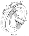
- the entire subassembly with fixtures may now be utilized for true tip machining of the blade tips 24. More particularly the blades 20, as assembled on to rotor 12 with the fixtures 30, 32 and bolts 48 all intersecured, may be affixed as a unit on a lathe as illustrated in FIG. 3. In FIG. 3 a lathe fixture 55 and portion of associated spindle 56 rotatably mounts the subassembly on the normal rotational axis of the wheel 10. By conventional lathe grinding and cutting, during spinning of the assembly illustrated in FIG. 3, the tips 24 of all of the blades 20 may be machined to the desired outer true diameter in a single, unified operation.
- the present invention contemplates an improved method of machining compressor or turbine blade outer diameters or blade tips 24 which includes the step of loosely assembling the annular array of blades 20 on the outer periphery of the rotor with platform portions 26 of each of the blades 20 protruding axially forwardly and aft from opposite sides of the rotor 12.
- Ring fixtures 30, 32 are mounted to opposite sides of rotor 12 and axially intersecured to one another by bolts 48 so as to axially fix and locate blades 20 by urging them against the datum provided by face 36 on fixture 30.
- a generally circumferentially uniform, radially outward force is then applied to the protruding portions of platforms 26 of each of the blades so as to radially position and fix all of the blades 20. Subsequently, the outer tips 24 may be machined with the blades 20 fixed in both a radial and axial direction.
Landscapes
- Engineering & Computer Science (AREA)
- Mechanical Engineering (AREA)
- General Engineering & Computer Science (AREA)
- Structures Of Non-Positive Displacement Pumps (AREA)
Claims (12)
- Méthode d'usinage de diamètres extérieurs d'aubes de turbine ou de compresseur, caractérisée par :
l'assemblage lâche d'un arrangement annulaire d'aubes (20) sur la périphérie extérieure d'un rotor (12), avec des portions de plate-forme (26) des aubes (20) saillant axialement vers l'avant et vers l'arrière à partir des côtés opposés du rotor (12);
le montage d'un premier et deuxième anneau de serrage (30, 32) sur les côtés opposés du rotor (12);
le blocage mutuel axial des anneaux de serrage (30, 32) pour fixer et localiser axialement les aubes (20);
l'application d'une force radialement extérieure généralement uniforme suivant la circonférence aux portions de plate-forme saillantes (26) des aubes (20) pour positionner et fixer radialement les aubes (20); et
l'usinage des extrémités extérieures (24) des aubes (20) alors qu'elles sont ainsi fixées axialement et radialement. - Méthode telle qu'exposée dans la revendication 1, dans laquelle ladite étape d'application comprend la compression d'un premier élément de poussée résilient (44) entre le premier anneau de serrage (30) et les portions de plate-forme saillantes vers l'avant (26), et la compression d'un deuxième élément de poussée résilient (46) entre le deuxième anneau de serrage (32) et les portions de plate-forme saillantes vers l'arrière (26) des aubes.
- Méthode telle qu'exposée dans la revendication 2, dans laquelle lesdits premier et deuxième éléments de poussée sont des anneaux toriques (44, 46).
- Méthode telle qu'exposée dans la revendication 3, dans laquelle l'étape de blocage mutuel axial comprend le boulonnage des premier et deuxième anneaux de serrage (30, 32) l'un à l'autre avec une pluralité de boulons (48) passant de façon lâche à travers des trous axiaux (54) dans le rotor.
- Méthode telle qu'exposée dans la revendication 4, dans laquelle l'étape de blocage mutuel axial comprend la poussée résiliente sur les aubes (20) pour repousser les portions de plate-forme saillantes vers l'avant (26) de celles-ci axialement en contact avec une face de référence s'étendant radialement (36) sur le premier anneau de serrage (30).
- Méthode telle qu'exposée dans la revendication 5, dans laquelle les aubes (20) sont poussées axialement par un troisième élément résilient (42) s'étendant entre le deuxième anneau de serrage (32) et les portions de plate-forme saillantes vers l'arrière (26) des aubes.
- Méthode telle qu'exposée dans la revendication 1, dans laquelle ladite étape d'assemblage comprend l'insertion des parties de racine (28) des aubes (20) dans des rainures en queue d'aronde (18) s'étendant généralement axialement, configurées de façon complémentaire, à la périphérie du rotor.
- Méthode telle qu'exposée dans la revendication 1, dans laquelle ladite étape d'usinage comprend le montage des aubes (20), du rotor (12) et des premier et deuxième anneaux de serrage (30, 32) en bloc sur un tour pour rotor (55).
- Ensemble de serrage pour positionner de façon sûre des aubes de compresseur ou de turbine (20) lâchement assemblées sur un rotor (12) pour simuler un positionnement réel lors d'un assemblage ultérieur dans un moteur à turbine à gaz, caractérisé par
un premier anneau de serrage annulaire (30) disposé sur un côté axial du rotor (12) et des aubes (20), ledit premier anneau de serrage (30) ayant des parois radiale et axiale annulaires (36, 34) faisant face à mais espacées d'une première portion de chacune des aubes (20) saillant axialement à partir du rotor (12);
un premier élément annulaire de poussée résilient (44) touchant lesdites parois radiale et axiale (36, 34) du premier anneau de serrage (30) et lesdites premières portions des aubes (20);
un deuxième anneau de serrage annulaire (32) disposé sur un côté axial opposé du rotor (12) et des aubes (20), ledit deuxième anneau de serrage (32) ayant des parois radiale et axiale annulaires (40, 38) faisant face à mais espacées d'une deuxième portion de chacune des aubes (20) saillant axialement à partir du rotor (12);
un deuxième élément annulaire de poussée résilient (46) touchant lesdites parois radiale et axiale (40, 38) du deuxième anneau de serrage (32) et lesdites deuxièmes portions des aubes (20); et
des moyens (48) pour serrer axialement lesdits premier et deuxième anneaux de serrage (30, 32) l'un à l'autre et comprimer ensuite lesdits deux premier et deuxième éléments de poussée (44, 46) pour repousser lesdites aubes (20) radialement par rapport audit rotor (12) afin de simuler les positions d'un assemblage réel dans le moteur. - Dispositif de serrage tel qu'exposé dans la revendication 9, dans lequel chacun desdits premier et deuxième éléments de poussée (44, 46) est un anneau torique annulaire en élastomère.
- Dispositif de serrage tel qu'exposé dans la revendication 9, comprenant en outre un troisième élément de poussée (42) s'étendant entre ledit deuxième anneau de serrage (32) et lesdites deuxièmes portions des aubes (20) pour repousser lesdites premières portions des aubes (20) en contact axial avec ladite paroi radiale (36) dudit premier anneau de serrage (30).
- Dispositif de serrage tel qu'exposé dans la revendication 11, dans lequel ledit troisième élément de poussée (42) est de configuration annulaire et est constitué d'une matière élastomère compressible.
Applications Claiming Priority (2)
| Application Number | Priority Date | Filing Date | Title |
|---|---|---|---|
| US07/812,776 US5191711A (en) | 1991-12-23 | 1991-12-23 | Compressor or turbine blade manufacture |
| US812776 | 1991-12-23 |
Publications (2)
| Publication Number | Publication Date |
|---|---|
| EP0548724A1 EP0548724A1 (fr) | 1993-06-30 |
| EP0548724B1 true EP0548724B1 (fr) | 1995-11-15 |
Family
ID=25210595
Family Applications (1)
| Application Number | Title | Priority Date | Filing Date |
|---|---|---|---|
| EP92121233A Expired - Lifetime EP0548724B1 (fr) | 1991-12-23 | 1992-12-14 | Procédé de fabrication d'aubes de turbine ou de compresseur |
Country Status (5)
| Country | Link |
|---|---|
| US (2) | US5191711A (fr) |
| EP (1) | EP0548724B1 (fr) |
| DE (1) | DE69206111T2 (fr) |
| DK (1) | DK0548724T3 (fr) |
| ES (1) | ES2089354T3 (fr) |
Families Citing this family (48)
| Publication number | Priority date | Publication date | Assignee | Title |
|---|---|---|---|---|
| US5558500A (en) * | 1994-06-07 | 1996-09-24 | Alliedsignal Inc. | Elastomeric seal for axial dovetail rotor blades |
| US5822841A (en) * | 1996-12-17 | 1998-10-20 | United Technologies Corporation | IBR fixture |
| US5971710A (en) * | 1997-10-17 | 1999-10-26 | United Technologies Corporation | Turbomachinery blade or vane with a permanent machining datum |
| US6158104A (en) * | 1999-08-11 | 2000-12-12 | General Electric Co. | Assembly jig for use with integrally covered bucket blades |
| US6179567B1 (en) | 1999-08-18 | 2001-01-30 | United Technologies Corporation | Turbomachinery blade or vane with a survivable machining datum |
| FR2817783B1 (fr) * | 2000-12-07 | 2003-02-21 | Snecma Moteurs | Outillage de maintien d'une aube, et son application au soudage par friction des aubes |
| US6820468B2 (en) | 2001-03-26 | 2004-11-23 | General Electric Company | Fixture for holding a gas turbine engine blade |
| US6502304B2 (en) | 2001-05-15 | 2003-01-07 | General Electric Company | Turbine airfoil process sequencing for optimized tip performance |
| US6844515B2 (en) | 2001-10-10 | 2005-01-18 | Brett Wayne Byrnes | Method and apparatus for turbine blade machining |
| US6560890B1 (en) | 2002-02-21 | 2003-05-13 | General Electric Company | Fixture for locating and clamping a part for laser drilling |
| US7219408B2 (en) * | 2002-09-24 | 2007-05-22 | General Electric Company | Tool for securing a component |
| US6832892B2 (en) * | 2002-12-11 | 2004-12-21 | General Electric Company | Sealing of steam turbine bucket hook leakages using a braided rope seal |
| US7052379B2 (en) * | 2002-12-27 | 2006-05-30 | General Electric Company | Methods and apparatus for machining a coupling |
| US6964557B2 (en) * | 2003-02-03 | 2005-11-15 | General Electric Company | Methods and apparatus for coupling a component to a turbine engine blade |
| US6933459B2 (en) * | 2003-02-03 | 2005-08-23 | General Electric Company | Methods and apparatus for fabricating a turbine engine blade |
| US7334331B2 (en) * | 2003-12-18 | 2008-02-26 | General Electric Company | Methods and apparatus for machining components |
| RU2257277C1 (ru) * | 2004-05-31 | 2005-07-27 | Открытое акционерное общество "Научно-производственное объединение "Сатурн" | Способ изготовления лопаток газотурбинного двигателя |
| GB0412775D0 (en) * | 2004-06-09 | 2004-07-07 | Rolls Royce Plc | Method of replacing damaged aerofoil |
| US7114920B2 (en) * | 2004-06-25 | 2006-10-03 | Pratt & Whitney Canada Corp. | Shroud and vane segments having edge notches |
| US7469452B2 (en) * | 2005-01-26 | 2008-12-30 | Honeywell International Inc. | Impeller weld restraining fixture |
| DE102005006047A1 (de) * | 2005-02-10 | 2006-09-07 | Mtu Aero Engines Gmbh | Verfahren zur Herstellung und/oder Reparatur eines integral beschaufelten Rotors |
| HRP20050289B1 (en) * | 2005-03-25 | 2009-10-31 | Brkić Blago | Process of turning suction edges of blades made of hard plastics or aluminium plate intended for fan rotary hub |
| US7752755B2 (en) * | 2005-10-14 | 2010-07-13 | General Electric Company | Methods and apparatus for manufacturing components |
| US7765658B2 (en) * | 2005-10-17 | 2010-08-03 | Pratt & Whitney Canada Corp. | Blade tip grinding tooling |
| GB2432426B8 (en) * | 2005-10-19 | 2007-11-20 | Rolls Royce Plc | Gas turbine engine simulator |
| US8844129B2 (en) * | 2007-10-15 | 2014-09-30 | United Technologies Corporation | Method and apparatus for hole crack removal |
| US8151458B2 (en) * | 2008-02-21 | 2012-04-10 | United Technologies Corporation | Non-metallic cover for a fixture |
| SG159412A1 (en) * | 2008-08-25 | 2010-03-30 | Pratt & Whitney Services Pte L | Fixture for compressor stator chord restoration repair |
| RU2403119C2 (ru) * | 2009-01-11 | 2010-11-10 | Открытое Акционерное Общество "Корпорация Всмпо-Ависма" | Способ изготовления лопаток газотурбинного двигателя |
| US20110171390A1 (en) * | 2010-01-08 | 2011-07-14 | United Technologies Corporation One Financial Plaza | Fixture for coating application |
| US9458855B2 (en) * | 2010-12-30 | 2016-10-04 | Rolls-Royce North American Technologies Inc. | Compressor tip clearance control and gas turbine engine |
| RU2463125C2 (ru) * | 2011-01-11 | 2012-10-10 | Открытое Акционерное Общество "Корпорация Всмпо-Ависма" | Способ изготовления заготовок широкохордных пустотелых лопаток вентилятора газотурбинного двигателя |
| US8601689B2 (en) * | 2011-06-17 | 2013-12-10 | General Electric Company | Method and apparatus to repair a turbomachine rotor wheel |
| US20130097850A1 (en) * | 2011-10-24 | 2013-04-25 | General Electric Company | Apparatus and method for servicing a turbine component |
| FR2987069B1 (fr) * | 2012-02-21 | 2016-01-29 | Thermodyn | Roue radiale aubee a couronne de base libre radialement |
| US9145781B2 (en) * | 2012-06-11 | 2015-09-29 | United Technologies Corporation | Vane support assembly |
| US9982549B2 (en) | 2012-12-18 | 2018-05-29 | United Technologies Corporation | Turbine under platform air seal strip |
| EP2767678A1 (fr) * | 2013-02-19 | 2014-08-20 | Siemens Aktiengesellschaft | Roue aubagée et procédé de fabrication d'une aube |
| EP2808124A1 (fr) | 2013-05-29 | 2014-12-03 | MTU Aero Engines GmbH | Procédé et dispositif destinés au traitement d'aubes de turbine |
| US20150118031A1 (en) * | 2013-10-25 | 2015-04-30 | Krishna Kumar Bindingnavale Ranga | System and a method of installing a tip shroud ring in turbine disks |
| GB201406921D0 (en) * | 2014-04-17 | 2014-06-04 | Advanced Mfg Sheffield Ltd | Apparatus and method for vibration mitigation |
| BE1022882A9 (fr) * | 2015-03-30 | 2017-02-09 | Safran Aero Boosters Sa | Tournage a choc d'extremites d'aubes de blum de compresseur de turbomachine axiale |
| DE102015220883A1 (de) * | 2015-10-26 | 2017-04-27 | Siemens Aktiengesellschaft | Dummy-Radscheibe und Verfahren zum Bearbeiten von Schaufeln |
| US9879536B2 (en) | 2015-12-21 | 2018-01-30 | General Electric Company | Surface treatment of turbomachinery |
| CN106737172B (zh) * | 2016-12-21 | 2018-11-27 | 中国南方航空工业(集团)有限公司 | 磨削装置 |
| US11060949B2 (en) * | 2018-07-02 | 2021-07-13 | Chromalloy Gas Turbine Llc | Systems and methods for modal testing of turbine blades |
| IT201900014739A1 (it) * | 2019-08-13 | 2021-02-13 | Ge Avio Srl | Elementi di trattenimento delle pale per turbomacchine. |
| EP4481209B1 (fr) * | 2023-06-19 | 2025-11-12 | Rolls-Royce plc | Fixation pour composants |
Family Cites Families (22)
| Publication number | Priority date | Publication date | Assignee | Title |
|---|---|---|---|---|
| US1601402A (en) * | 1921-01-15 | 1926-09-28 | Lorenzen Christian | Gas turbine |
| NL49923C (fr) * | 1938-03-21 | 1941-02-15 | ||
| US2265592A (en) * | 1939-01-16 | 1941-12-09 | Allis Chalmers Mfg Co | Turbine blade |
| US2428674A (en) * | 1943-05-17 | 1947-10-07 | Ford Motor Co | Apparatus for constructing aircraft wings |
| US2565925A (en) * | 1946-04-10 | 1951-08-28 | Rolls Royce | Method of manufacturing guide vanes for axial flow turbines and compressors |
| US2507079A (en) * | 1946-06-19 | 1950-05-09 | Charles H Zimmerman | Abrading mechanism |
| DE881615C (de) * | 1951-01-20 | 1953-07-02 | Maschf Augsburg Nuernberg Ag | Verfahren und Vorrichtung zur Ausrichtung und Bearbeitung eines Satzes von keramischen Schaufeln fuer einen Turbinenlaeufer |
| US2729422A (en) * | 1951-04-06 | 1956-01-03 | Maschf Augsburg Nuernberg Ag | Shaped article of ceramic material |
| DE939029C (de) * | 1951-12-09 | 1956-02-16 | Siemens Ag | Verfahren zur Herstellung einer aus Einzelschaufeln aufgebauten Beschaufelung fuer Turbomaschinen, insbesondere Dampf- oder Gasturbinen |
| GB749997A (en) * | 1952-07-11 | 1956-06-06 | Power Jets Res & Dev Ltd | Process and apparatus for making turbine or compressor blades |
| FR2218777A5 (fr) * | 1973-02-16 | 1974-09-13 | Peugeot & Renault | |
| US4022545A (en) * | 1974-09-11 | 1977-05-10 | Avco Corporation | Rooted aerodynamic blade and elastic roll pin damper construction |
| US4164102A (en) * | 1976-01-29 | 1979-08-14 | Daimler-Benz Aktiengesellschaft | Process for the manufacture of a ceramic axial turbine wheel |
| US4009874A (en) * | 1976-04-26 | 1977-03-01 | Emerson Dee Hughey | Propeller making apparatus |
| CH601665A5 (fr) * | 1977-03-23 | 1978-07-14 | Charmilles Sa Ateliers | |
| US4449703A (en) * | 1978-09-01 | 1984-05-22 | Robinson Helicopter Company | Apparatus for bonding main rotor blades |
| US4266454A (en) * | 1978-09-21 | 1981-05-12 | Ammco Tools, Inc. | Method and apparatus for dampening vibrations during turning of a rotor |
| US4501095A (en) * | 1983-06-07 | 1985-02-26 | United Technologies Corporation | Method and apparatus for grinding turbine engine rotor assemblies using dynamic optical measurement system |
| US4575911A (en) * | 1985-02-08 | 1986-03-18 | Abdite Industries, Inc. | Method and apparatus for constructing turbine components |
| DE3802741C2 (de) * | 1988-01-30 | 1997-02-13 | Asea Brown Boveri | Verfahren zur Verspannung von Schaufeln |
| US4838069A (en) * | 1988-02-12 | 1989-06-13 | United Technologies Corporation | Apparatus for fabricating integrally bladed rotors |
| US4836749A (en) * | 1988-02-19 | 1989-06-06 | Westinghouse Electric Corp. | Pre-load device for a turbomachine rotor |
-
1991
- 1991-12-23 US US07/812,776 patent/US5191711A/en not_active Expired - Fee Related
-
1992
- 1992-10-13 US US07/959,893 patent/US5544873A/en not_active Expired - Lifetime
- 1992-12-14 EP EP92121233A patent/EP0548724B1/fr not_active Expired - Lifetime
- 1992-12-14 ES ES92121233T patent/ES2089354T3/es not_active Expired - Lifetime
- 1992-12-14 DK DK92121233.8T patent/DK0548724T3/da active
- 1992-12-14 DE DE69206111T patent/DE69206111T2/de not_active Expired - Fee Related
Also Published As
| Publication number | Publication date |
|---|---|
| EP0548724A1 (fr) | 1993-06-30 |
| ES2089354T3 (es) | 1996-10-01 |
| DE69206111D1 (de) | 1995-12-21 |
| DK0548724T3 (da) | 1995-12-27 |
| US5544873A (en) | 1996-08-13 |
| US5191711A (en) | 1993-03-09 |
| DE69206111T2 (de) | 1996-04-25 |
Similar Documents
| Publication | Publication Date | Title |
|---|---|---|
| EP0548724B1 (fr) | Procédé de fabrication d'aubes de turbine ou de compresseur | |
| US4349318A (en) | Boltless blade retainer for a turbine wheel | |
| JP4837203B2 (ja) | 偏心によりバランスされたブリスク | |
| US5101557A (en) | Method for machining rotors | |
| US6575703B2 (en) | Turbine disk side plate | |
| US6588298B2 (en) | Rotor balancing system for turbomachinery | |
| US4664599A (en) | Two stage turbine rotor assembly | |
| US5713721A (en) | Retention system for the blades of a rotary machine | |
| RU2361090C2 (ru) | Устройство для балансировки вращающейся детали, в частности ротора турбореактивного двигателя | |
| US9328621B2 (en) | Rotor blade assembly tool for gas turbine engine | |
| EP1548238A2 (fr) | Procédé et appareil d'optimisation de jeu radial d'un boítier d'un moteur à turbine | |
| US7591634B2 (en) | Stator shim welding | |
| US10436224B2 (en) | Method and apparatus for balancing a rotor | |
| CA2370219A1 (fr) | Carenage et methode d'usinage | |
| GB2452932A (en) | Turbine or turbomachine with axial shaft-mounted compressor and turbine blades | |
| US20210115805A1 (en) | Balanced Circumferential Seal | |
| EP1424518B1 (fr) | Joint brosses à jeu réglable | |
| US3765795A (en) | Compositely formed rotors and their manufacture | |
| US6010304A (en) | Blade retention system for a variable rotor blade | |
| US5142762A (en) | Air cycle machine alignment | |
| US20200200019A1 (en) | Turbomachine disc cover mounting arrangement | |
| US3817655A (en) | Stator blade mounting structure for turbomachines | |
| US5257905A (en) | Rotor coupling anti-windage apparatus | |
| US20060251520A1 (en) | Turbine module for a gas-turbine engine with rotor that includes a monoblock body | |
| US4653984A (en) | Turbine module assembly device |
Legal Events
| Date | Code | Title | Description |
|---|---|---|---|
| PUAI | Public reference made under article 153(3) epc to a published international application that has entered the european phase |
Free format text: ORIGINAL CODE: 0009012 |
|
| AK | Designated contracting states |
Kind code of ref document: A1 Designated state(s): DE DK ES FR GB SE |
|
| 17P | Request for examination filed |
Effective date: 19931214 |
|
| RAP1 | Party data changed (applicant data changed or rights of an application transferred) |
Owner name: ALLIEDSIGNAL INC. |
|
| 17Q | First examination report despatched |
Effective date: 19950220 |
|
| GRAA | (expected) grant |
Free format text: ORIGINAL CODE: 0009210 |
|
| AK | Designated contracting states |
Kind code of ref document: B1 Designated state(s): DE DK ES FR GB SE |
|
| REG | Reference to a national code |
Ref country code: ES Ref legal event code: BA2A Ref document number: 2089354 Country of ref document: ES Kind code of ref document: T3 |
|
| ET | Fr: translation filed | ||
| PG25 | Lapsed in a contracting state [announced via postgrant information from national office to epo] |
Ref country code: SE Effective date: 19951215 |
|
| REF | Corresponds to: |
Ref document number: 69206111 Country of ref document: DE Date of ref document: 19951221 |
|
| REG | Reference to a national code |
Ref country code: DK Ref legal event code: T3 |
|
| PG25 | Lapsed in a contracting state [announced via postgrant information from national office to epo] |
Ref country code: DK Effective date: 19960215 |
|
| REG | Reference to a national code |
Ref country code: DK Ref legal event code: EBP |
|
| PG25 | Lapsed in a contracting state [announced via postgrant information from national office to epo] |
Ref country code: DE Effective date: 19960903 |
|
| PLBE | No opposition filed within time limit |
Free format text: ORIGINAL CODE: 0009261 |
|
| STAA | Information on the status of an ep patent application or granted ep patent |
Free format text: STATUS: NO OPPOSITION FILED WITHIN TIME LIMIT |
|
| REG | Reference to a national code |
Ref country code: ES Ref legal event code: FG2A Ref document number: 2089354 Country of ref document: ES Kind code of ref document: T3 |
|
| EUG | Se: european patent has lapsed |
Ref document number: 92121233.8 |
|
| PG25 | Lapsed in a contracting state [announced via postgrant information from national office to epo] |
Ref country code: FR Effective date: 19961031 |
|
| 26N | No opposition filed | ||
| REG | Reference to a national code |
Ref country code: ES Ref legal event code: FG2A Ref document number: 2089354 Country of ref document: ES Kind code of ref document: T3 |
|
| PG25 | Lapsed in a contracting state [announced via postgrant information from national office to epo] |
Ref country code: GB Effective date: 19961214 |
|
| PG25 | Lapsed in a contracting state [announced via postgrant information from national office to epo] |
Ref country code: ES Free format text: LAPSE BECAUSE OF NON-PAYMENT OF DUE FEES Effective date: 19961215 |
|
| REG | Reference to a national code |
Ref country code: FR Ref legal event code: ST |
|
| GBPC | Gb: european patent ceased through non-payment of renewal fee |
Effective date: 19961214 |
|
| REG | Reference to a national code |
Ref country code: ES Ref legal event code: FD2A Effective date: 19970113 |
|
| PG25 | Lapsed in a contracting state [announced via postgrant information from national office to epo] |
Ref country code: FR Effective date: 19951231 |