EP0548735A1 - Bandage pneumatique ayant des propriétés différentes du coté axialement extérieur par rapport au véhicule - Google Patents
Bandage pneumatique ayant des propriétés différentes du coté axialement extérieur par rapport au véhicule Download PDFInfo
- Publication number
- EP0548735A1 EP0548735A1 EP92121282A EP92121282A EP0548735A1 EP 0548735 A1 EP0548735 A1 EP 0548735A1 EP 92121282 A EP92121282 A EP 92121282A EP 92121282 A EP92121282 A EP 92121282A EP 0548735 A1 EP0548735 A1 EP 0548735A1
- Authority
- EP
- European Patent Office
- Prior art keywords
- belt
- bandage
- winding
- turns
- edge
- Prior art date
- Legal status (The legal status is an assumption and is not a legal conclusion. Google has not performed a legal analysis and makes no representation as to the accuracy of the status listed.)
- Withdrawn
Links
- 239000000463 material Substances 0.000 claims abstract description 9
- 230000002787 reinforcement Effects 0.000 claims abstract description 4
- 238000004804 winding Methods 0.000 claims description 36
- 230000003014 reinforcing effect Effects 0.000 claims description 6
- 238000004519 manufacturing process Methods 0.000 claims description 4
- 239000010410 layer Substances 0.000 description 8
- 239000011324 bead Substances 0.000 description 2
- 238000010586 diagram Methods 0.000 description 2
- 239000004677 Nylon Substances 0.000 description 1
- 229910000831 Steel Inorganic materials 0.000 description 1
- 230000001934 delay Effects 0.000 description 1
- 230000000694 effects Effects 0.000 description 1
- 229920001778 nylon Polymers 0.000 description 1
- 239000004033 plastic Substances 0.000 description 1
- 229920003023 plastic Polymers 0.000 description 1
- 239000002356 single layer Substances 0.000 description 1
- 239000010959 steel Substances 0.000 description 1
Images
Classifications
-
- B—PERFORMING OPERATIONS; TRANSPORTING
- B60—VEHICLES IN GENERAL
- B60C—VEHICLE TYRES; TYRE INFLATION; TYRE CHANGING; CONNECTING VALVES TO INFLATABLE ELASTIC BODIES IN GENERAL; DEVICES OR ARRANGEMENTS RELATED TO TYRES
- B60C9/00—Reinforcements or ply arrangement of pneumatic tyres
- B60C9/18—Structure or arrangement of belts or breakers, crown-reinforcing or cushioning layers
- B60C9/20—Structure or arrangement of belts or breakers, crown-reinforcing or cushioning layers built-up from rubberised plies each having all cords arranged substantially parallel
- B60C9/22—Structure or arrangement of belts or breakers, crown-reinforcing or cushioning layers built-up from rubberised plies each having all cords arranged substantially parallel the plies being arranged with all cords disposed along the circumference of the tyre
- B60C9/2204—Structure or arrangement of belts or breakers, crown-reinforcing or cushioning layers built-up from rubberised plies each having all cords arranged substantially parallel the plies being arranged with all cords disposed along the circumference of the tyre obtained by circumferentially narrow strip winding
-
- B—PERFORMING OPERATIONS; TRANSPORTING
- B60—VEHICLES IN GENERAL
- B60C—VEHICLE TYRES; TYRE INFLATION; TYRE CHANGING; CONNECTING VALVES TO INFLATABLE ELASTIC BODIES IN GENERAL; DEVICES OR ARRANGEMENTS RELATED TO TYRES
- B60C9/00—Reinforcements or ply arrangement of pneumatic tyres
- B60C9/18—Structure or arrangement of belts or breakers, crown-reinforcing or cushioning layers
- B60C9/30—Structure or arrangement of belts or breakers, crown-reinforcing or cushioning layers asymmetric to the midcircumferential plane of the tyre
Definitions
- the invention relates to a pneumatic vehicle tire with a carcass, a reinforcement belt and a covering bandage and with different properties on the inside and outside of the tire on the vehicle.
- the invention has for its object to provide a pneumatic vehicle tire in which different tire properties are present at least in the region of the two belt edges.
- the covering bandage which is in the form of a wrapping bandage produced by winding strip material, is constructed asymmetrically in the two halves to the left and right of the central plane of the tire.
- the winding bandage is constructed in such a way that it exerts a greater reinforcing effect in the tire half facing away from the vehicle.
- An advantage of the invention is that, in order to achieve uneven tire properties, only measures on the wrapping bandage are carried out on the side of the tire facing and facing away from the vehicle. All other parts of the tire can remain symmetrical.
- the measures on the winding bandage can be carried out in a simple manner during their production, without there being any significant time delays or further work steps.
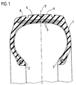
- the pneumatic vehicle tire which is essentially made of rubber or rubber-like plastics, has a carcass, preferably a radial carcass 1, which is anchored in the beads 2 by looping around tensile bead cores 3.
- a conventional reinforcing belt 5 between it and the tread 4, which can consist, for example, of two steel cord plies arranged in a cross structure.
- the belt 5 is surrounded radially on the outside by a covering bandage in the form of a wrapping bandage 6, which covers the belt 5 in its full width.
- the winding bandage 6 is constructed asymmetrically with respect to the tire center plane 7, in particular it is in the area of the outside of the tire, ie the side of the tire turned away from a vehicle, reinforced. This belt edge area is designated 8 in FIG. 1.
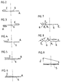
- FIGS. 2 to 8 show individual variants of the wrapping bandage 6 according to FIG. 1.
- the wrapping bandage is produced by winding a conventional strip of material, e.g. can consist of rubberized nylon cord and can have a width of preferably 8 to 25 mm.
- the thread density is in the range of about 10 threads per 1 cm strip width.
- the winding bandages 6 of FIGS. 2 to 6 are produced with the aid of a single winding head, while in the examples of FIGS. 7 and 8 the winding bandage 6 is produced by means of two winding heads.
- the beginning of the wrapping bandage 6 is designated with the letter A, while the letter E means the end of the bandage.
- a continuous line is intended to indicate that the winding bandage 6, which is wound from a strip, is present with closely lying turns or with a slight distance between adjacent turns.
- the beginning of the wrapping bandage 6 lies in the area of one belt edge.
- the bandage completely covers the belt width and is then returned from the other end of the belt over a certain width, so that there is a double layer covering in the edge region of the second belt edge.
- the complete winding bandage 6 can be produced in one work step.
- the same effect of the wrapping bandage 6 results if, in two working steps, the layer that extends across the entire belt width is first produced and then a second layer is produced in the belt edge area.
- FIG. 3 differs from that described above in that a winding bandage 6 with three effective areas is produced.
- a winding bandage 6 which is formed in three layers in the left belt edge area, while it has a single layer in the middle area and is formed in two layers in the right belt edge area.
- the example according to FIG. 4 differs from that of FIG. 2 in that the additional layer present in one edge region consists of overlapping turns.
- This winding bandage 6 can also be produced in the manner shown in a single step.
- FIG. 4 differs from that described above in that a winding bandage 6 with three effective areas is produced.
- the winding bandage 6 is initially produced over the full belt width from overlapping turns, while the part additionally present in the area of the belt edge consists of tightly lying turns.
- the winding bandage 6 consists of overlapping turns over the full belt width, the overlap dimension increasing from one belt edge to the other, preferably increasing continuously.
- two winding bandages 6 are produced simultaneously by means of two winding heads.
- the first bandage is located in the left belt edge area and consists of an inner layer with tightly lying turns and an outer layer with overlapping turns.
- the rest of the predominant belt width is covered by a winding bandage that is wound from tightly lying turns.
- two winding bandages 6 are likewise produced simultaneously by means of two winding heads, in order to achieve different tire properties different strip widths are used in the two tire halves, on the other hand the turns are overlapping in the wrapping bandage with the strip width B, while in the wrapping bandage with the strip width A the turns are close together.
- a greater reinforcing effect is achieved in the left half than in the right half.
- a different reinforcing effect in the two halves of the tire can also be achieved by laying on the strip of a wrapping bandage 6 with different strip tension or thread tension.
- the strip tension increases continuously from the right belt edge to the left belt edge, so that there is again an increased reinforcing effect in the left half of the tire.
Landscapes
- Engineering & Computer Science (AREA)
- Mechanical Engineering (AREA)
- Tires In General (AREA)
- Tyre Moulding (AREA)
Applications Claiming Priority (2)
| Application Number | Priority Date | Filing Date | Title |
|---|---|---|---|
| DE19914142724 DE4142724A1 (de) | 1991-12-21 | 1991-12-21 | Fahrzeugluftreifen mit unterschiedlichen eigenschaften auf der innen- und aussenseite des reifens am fahrzeug |
| DE4142724 | 1991-12-21 |
Publications (1)
| Publication Number | Publication Date |
|---|---|
| EP0548735A1 true EP0548735A1 (fr) | 1993-06-30 |
Family
ID=6447985
Family Applications (1)
| Application Number | Title | Priority Date | Filing Date |
|---|---|---|---|
| EP92121282A Withdrawn EP0548735A1 (fr) | 1991-12-21 | 1992-12-15 | Bandage pneumatique ayant des propriétés différentes du coté axialement extérieur par rapport au véhicule |
Country Status (3)
| Country | Link |
|---|---|
| EP (1) | EP0548735A1 (fr) |
| JP (1) | JPH05246211A (fr) |
| DE (1) | DE4142724A1 (fr) |
Cited By (1)
| Publication number | Priority date | Publication date | Assignee | Title |
|---|---|---|---|---|
| EP2561980A1 (fr) * | 2011-08-22 | 2013-02-27 | Sumitomo Rubber Industries, Ltd. | Procédé de production de pneus |
Families Citing this family (5)
| Publication number | Priority date | Publication date | Assignee | Title |
|---|---|---|---|---|
| JP4188601B2 (ja) * | 2002-01-08 | 2008-11-26 | 住友ゴム工業株式会社 | 空気入りラジアルタイヤ |
| JP5689642B2 (ja) * | 2010-10-13 | 2015-03-25 | 株式会社ブリヂストン | 航空機用空気入りタイヤ |
| JP6087248B2 (ja) * | 2013-09-18 | 2017-03-01 | 東洋ゴム工業株式会社 | 空気入りタイヤ |
| JP6126966B2 (ja) * | 2013-10-10 | 2017-05-10 | 東洋ゴム工業株式会社 | 空気入りタイヤ |
| CN113334814B (zh) * | 2021-07-01 | 2022-10-25 | 万达集团股份有限公司 | 一种提高非对称花纹轮胎高速性能的冠带条缠绕方式 |
Citations (8)
| Publication number | Priority date | Publication date | Assignee | Title |
|---|---|---|---|---|
| FR2386424A1 (fr) * | 1977-04-06 | 1978-11-03 | Uniroyal | Ceinture de renforcement pour enveloppe de pneumatique et enveloppe en comportant application |
| EP0305558A1 (fr) * | 1987-08-31 | 1989-03-08 | Bridgestone Corporation | Bandage pneumatique |
| EP0313362A2 (fr) * | 1987-10-21 | 1989-04-26 | Bridgestone Corporation | Bandage pneumatique radial ayant une section basse |
| EP0333628A2 (fr) * | 1988-03-17 | 1989-09-20 | The Goodyear Tire & Rubber Company | Bandage pneumatique |
| DE3911031A1 (de) * | 1988-04-05 | 1989-10-26 | Toyo Tire & Rubber Co | Radialreifen fuer personenwagen |
| EP0400859A2 (fr) * | 1989-05-31 | 1990-12-05 | Sp Reifenwerke Gmbh | Pneumatique pour véhicules |
| US4987938A (en) * | 1986-04-22 | 1991-01-29 | Bridgestone Corporation | Pneumatic tires including spirally wound auxiliary layer outside belt |
| EP0319588B1 (fr) * | 1987-06-18 | 1994-07-13 | Sumitomo Rubber Industries Limited | Pneu radial et production de ce pneu |
-
1991
- 1991-12-21 DE DE19914142724 patent/DE4142724A1/de not_active Withdrawn
-
1992
- 1992-12-15 EP EP92121282A patent/EP0548735A1/fr not_active Withdrawn
- 1992-12-17 JP JP4337549A patent/JPH05246211A/ja not_active Withdrawn
Patent Citations (8)
| Publication number | Priority date | Publication date | Assignee | Title |
|---|---|---|---|---|
| FR2386424A1 (fr) * | 1977-04-06 | 1978-11-03 | Uniroyal | Ceinture de renforcement pour enveloppe de pneumatique et enveloppe en comportant application |
| US4987938A (en) * | 1986-04-22 | 1991-01-29 | Bridgestone Corporation | Pneumatic tires including spirally wound auxiliary layer outside belt |
| EP0319588B1 (fr) * | 1987-06-18 | 1994-07-13 | Sumitomo Rubber Industries Limited | Pneu radial et production de ce pneu |
| EP0305558A1 (fr) * | 1987-08-31 | 1989-03-08 | Bridgestone Corporation | Bandage pneumatique |
| EP0313362A2 (fr) * | 1987-10-21 | 1989-04-26 | Bridgestone Corporation | Bandage pneumatique radial ayant une section basse |
| EP0333628A2 (fr) * | 1988-03-17 | 1989-09-20 | The Goodyear Tire & Rubber Company | Bandage pneumatique |
| DE3911031A1 (de) * | 1988-04-05 | 1989-10-26 | Toyo Tire & Rubber Co | Radialreifen fuer personenwagen |
| EP0400859A2 (fr) * | 1989-05-31 | 1990-12-05 | Sp Reifenwerke Gmbh | Pneumatique pour véhicules |
Cited By (1)
| Publication number | Priority date | Publication date | Assignee | Title |
|---|---|---|---|---|
| EP2561980A1 (fr) * | 2011-08-22 | 2013-02-27 | Sumitomo Rubber Industries, Ltd. | Procédé de production de pneus |
Also Published As
| Publication number | Publication date |
|---|---|
| DE4142724A1 (de) | 1993-07-01 |
| JPH05246211A (ja) | 1993-09-24 |
Similar Documents
| Publication | Publication Date | Title |
|---|---|---|
| DE69110954T2 (de) | Gürtelluftreifen für Motorräder und Verfahren zur Herstellung. | |
| DE2749517C2 (de) | Verfahren zum Herstellen von Reifen für Fahrzeugräder | |
| DE2713124C2 (de) | Verfahren zum Runderneuern eines Radialreifens mit Gürtel | |
| DE1811770B2 (de) | Vulkanisierbarer, im wesentlichen zylindrischer Rohling zum Herstellen eines Luftreifens | |
| DE69104542T2 (de) | Radialer Luftreifen für Motorräder. | |
| DE69106104T2 (de) | Luftreifen. | |
| DE602005003262T2 (de) | Verfahren zur Herstellung eines Verstärkungsmaterials für Reifen und seine Verwendung in der Reifenherstellung. | |
| DE2556930A1 (de) | Runderneuerter fahrzeugluftreifen | |
| EP0548735A1 (fr) | Bandage pneumatique ayant des propriétés différentes du coté axialement extérieur par rapport au véhicule | |
| DE69306166T2 (de) | Verbesserungen an Reifen-Verstärkungsstrukturen für Fahrzeugräder | |
| EP0052737B1 (fr) | Bandage pneumatique | |
| DE69901899T2 (de) | Reifen mit einer karkassenbewehrung mit zwei steifigkeiten | |
| EP1754615B1 (fr) | Bandage pneumatique pour véhicule | |
| EP0498183B1 (fr) | Bandage pneumatique pour véhicules et procédé de fabrication | |
| DE2941397A1 (de) | Fahrzeugluftreifen mit einem guertel | |
| DE1128314B (de) | Fahrzeugluftreifen | |
| EP0484831A1 (fr) | Bandage pneumatique pour bicyclette | |
| DE4439010C1 (de) | Fahrzeugluftreifen und Verfahren zur Herstellung eines Fahrzeugluftreifens | |
| DE4203568A1 (de) | Luftreifen | |
| DE68914101T2 (de) | Radialer Luftreifen für PKW. | |
| DE69117583T2 (de) | Verfahren zum Aufbringen eins Gürtels auf die Karkasse eines Radialreifens und verfahrensgemäss hergestellter Reifen | |
| EP0561176B1 (fr) | Bandage pneumatique pour véhicules | |
| DE4032072C2 (fr) | ||
| DE2804958A1 (de) | Fahrzeugluftreifen | |
| DE3201241C2 (fr) |
Legal Events
| Date | Code | Title | Description |
|---|---|---|---|
| PUAI | Public reference made under article 153(3) epc to a published international application that has entered the european phase |
Free format text: ORIGINAL CODE: 0009012 |
|
| AK | Designated contracting states |
Kind code of ref document: A1 Designated state(s): AT BE CH DE DK ES FR GB GR IT LI LU NL PT SE |
|
| STAA | Information on the status of an ep patent application or granted ep patent |
Free format text: STATUS: THE APPLICATION IS DEEMED TO BE WITHDRAWN |
|
| 18D | Application deemed to be withdrawn |
Effective date: 19931231 |
|
| PGFP | Annual fee paid to national office [announced via postgrant information from national office to epo] |
Ref country code: FR Payment date: 20010827 Year of fee payment: 9 |