EP0548748A1 - Dispositif de signalisation de distance résiduelle pour un véhicule entraîné par un accumulateur - Google Patents
Dispositif de signalisation de distance résiduelle pour un véhicule entraîné par un accumulateur Download PDFInfo
- Publication number
- EP0548748A1 EP0548748A1 EP92121304A EP92121304A EP0548748A1 EP 0548748 A1 EP0548748 A1 EP 0548748A1 EP 92121304 A EP92121304 A EP 92121304A EP 92121304 A EP92121304 A EP 92121304A EP 0548748 A1 EP0548748 A1 EP 0548748A1
- Authority
- EP
- European Patent Office
- Prior art keywords
- distance
- electric vehicle
- indicator device
- route
- measuring
- Prior art date
- Legal status (The legal status is an assumption and is not a legal conclusion. Google has not performed a legal analysis and makes no representation as to the accuracy of the status listed.)
- Granted
Links
- 230000006870 function Effects 0.000 claims abstract description 20
- 238000005259 measurement Methods 0.000 claims abstract description 4
- 230000006399 behavior Effects 0.000 claims description 2
- 230000003213 activating effect Effects 0.000 claims 1
- 238000010586 diagram Methods 0.000 description 13
- 239000000446 fuel Substances 0.000 description 4
- 230000008859 change Effects 0.000 description 3
- 230000032683 aging Effects 0.000 description 2
- 238000000034 method Methods 0.000 description 2
- 230000001133 acceleration Effects 0.000 description 1
- 238000002485 combustion reaction Methods 0.000 description 1
- 238000007599 discharging Methods 0.000 description 1
- 238000004519 manufacturing process Methods 0.000 description 1
- 238000012986 modification Methods 0.000 description 1
- 230000004048 modification Effects 0.000 description 1
- 230000009467 reduction Effects 0.000 description 1
Images
Classifications
-
- B—PERFORMING OPERATIONS; TRANSPORTING
- B60—VEHICLES IN GENERAL
- B60L—PROPULSION OF ELECTRICALLY-PROPELLED VEHICLES; SUPPLYING ELECTRIC POWER FOR AUXILIARY EQUIPMENT OF ELECTRICALLY-PROPELLED VEHICLES; ELECTRODYNAMIC BRAKE SYSTEMS FOR VEHICLES IN GENERAL; MAGNETIC SUSPENSION OR LEVITATION FOR VEHICLES; MONITORING OPERATING VARIABLES OF ELECTRICALLY-PROPELLED VEHICLES; ELECTRIC SAFETY DEVICES FOR ELECTRICALLY-PROPELLED VEHICLES
- B60L58/00—Methods or circuit arrangements for monitoring or controlling batteries or fuel cells, specially adapted for electric vehicles
- B60L58/10—Methods or circuit arrangements for monitoring or controlling batteries or fuel cells, specially adapted for electric vehicles for monitoring or controlling batteries
- B60L58/12—Methods or circuit arrangements for monitoring or controlling batteries or fuel cells, specially adapted for electric vehicles for monitoring or controlling batteries responding to state of charge [SoC]
- B60L58/13—Maintaining the SoC within a determined range
-
- Y—GENERAL TAGGING OF NEW TECHNOLOGICAL DEVELOPMENTS; GENERAL TAGGING OF CROSS-SECTIONAL TECHNOLOGIES SPANNING OVER SEVERAL SECTIONS OF THE IPC; TECHNICAL SUBJECTS COVERED BY FORMER USPC CROSS-REFERENCE ART COLLECTIONS [XRACs] AND DIGESTS
- Y02—TECHNOLOGIES OR APPLICATIONS FOR MITIGATION OR ADAPTATION AGAINST CLIMATE CHANGE
- Y02T—CLIMATE CHANGE MITIGATION TECHNOLOGIES RELATED TO TRANSPORTATION
- Y02T10/00—Road transport of goods or passengers
- Y02T10/60—Other road transportation technologies with climate change mitigation effect
- Y02T10/70—Energy storage systems for electromobility, e.g. batteries
Definitions
- This invention relates to an residual range indicator device for a storage battery-powered vehicle.
- Storage battery characteristics also change substantially as they degrade due to ageing.
- the object of the present invention is to provide a residual range indicator device for a storage battery-powered electric vehicle and for the stated applications which is completely automatic, reliable and of low cost, and which provides a precise and reliable indication of the distance which the electric vehicle can still travel, independently of the storage battery conditions and taking account of the type of route which the vehicle is undertaking.
- a residual range indicator device for a storage battery-powered electric vehicle comprising essentially a processor unit connected to a memory unit and to a display device, characterised in that said indicator device is further connected to a device for measuring the distance travelled by said electric vehicle and to a device for measuring the charge present in the storage batteries, said memory unit containing data relative to the electrical charge consumption of the vehicle as a function of the distance travelled, as a function of the type of route and as a function of at least one other measurable physical parameter, said processor unit executing a control programme comprising the following functions: identifying on the basis of the measurements made by said travelled distance measuring device and by said charge measuring device the type of route travelled by the electric vehicle; calculating on the basis of said data contained in said memory unit the distance which the electric vehicle is still able to travel; and displaying the value of said distance on said display device.
- the residual range indicator device is also connected to a battery charger, said control programme executed by said processor unit comprising the function of updating, whenever said processor unit receives a charge commencement signal from said battery charger, the data contained in said memory unit by adding data relative to the last route followed, so that the indicator device is able, during normal use of the electric vehicle, to increase its degree of knowledge of the behaviour of the vehicle in relation to ever more route types.
- the advantages achieved by the present invention are essentially that in this manner the residual range indication is presented to the user in the form of a distance still to be travelled rather than in other units which cannot be immediately interpreted.
- This indication results from a prediction which takes account of the type of route along which the vehicle is used implies that the indication dynamically adapts to route change.
- the accuracy of the indicator device tends statistically to increase with the use of the vehicle, because of its capacity to absorb new data relative to different types of route during normal use of the vehicle.
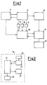
- a battery charger 11 is connected to a group of storage batteries 12 which power an electric motor 13.
- a trip odometer 14 connected to the electric motor 13, measures the distance travelled by the vehicle and displays the number of kilometres travelled on a display 15.
- the odometer 14 is also connected to a residual range indicator device, indicated overall by 16.
- the residual range indicator device 16 is connected to the storage battery group 12 via an ampere-hour meter 17, a voltmeter 18 and a temperature sensor 19.
- the temperature sensor 19 measures the temperature of the storage battery group 12, while the voltmeter 18 measures the voltage across the storage battery terminals.
- the ampere-hour meter 17 measures the quantity of charge present in the storage batteries 12 by integrating with respect to time the electric current delivered by the storage batteries.
- the ampere-hour meter 17 can be usefully reset to a predefined value to nullify any errors accumulated with time.
- the residual range indicator device 16 is also connected to the battery charger 11, so as to receive a signal of charging underway.
- the residual range indicator device 16 comprises a microprocessor 21 connected to an alphanumerical display 22 and to a RAM memory 23.
- the RAM 23 is provided with a buffer battery 24 to prevent loss of the data stored in it should the main electrical supply fail.
- the microprocessor 21 is also connected to a flashing lamp 25.
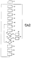
- the operation of the residual range indicator device 16 will be more apparent from the flow diagram of Figure 3.
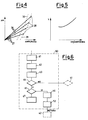
- a number of different types of route such as town routes, motorway routes, mixed routes etc. are travelled several times using one or more standard vehicles. Each type of route is repeated at systematically different speeds and accelerations to obtain various "specific consumption” values (kilometres/ampere-hour).
- the end of each route is always determined by the permanent attaining of a minimum battery voltage. This minimum voltage is defined by the storage battery constructor on the basis of the discharge time and the temperature. At the end of each route the ampere-hours consumed, the kilometers travelled and the storage battery temperature are read. These data enable a respective diagram to be drawn for each temperature range.
- each straight line of the plurality 26 represents a different type of route. As the number of routes which can in reality be travelled is necessarily finite, some intermediate straight lines can be obtained by interpolation.
- the data relative to each straight line of the diagram are fed (step 41) into the RAM 23 in the form of pairs of gradients 27 and terminal points 28 indicating zero residual range.
- the graph of Figure 4 also shows two curves 29 and 30.
- the curve 29, which joins the points 28, represents a zero residual range curve, whereas the curve 30 represents a "reserve fuel" pattern.
- the microprocessor 21 selects (step 42) the data of one route among those memorized in the RAM 23 and defined during the calibration step 41 as standard routes. This standard route hence becomes the current route. Having selected a route, the microprocessor 21 reads (step 43) and memorizes (step 44) the value in ampere-hours of the charge present in the storage batteries 12.
- the microprocessor 21 calculates the number of kilometres which can still be travelled (step 45). This operation is effected by simple algebraic operations starting from the value of the zero residual range point 28 and the number of kilometres corresponding, in the current route, to the charge value read during step 43.
- step 46 the microprocessor 21 initialises a trip odometer at zero.
- step 47 a reading is taken of the number of kilometres travelled by the vehicle from the commencement of step 43, and the trip odometer is suitably incremented.
- the microprocessor 21 then checks (test 49) that this result is equal to or less than a predetermined value, for example ten kilometres.
- the indicator device enters a "reserve fuel” control state (step 50).
- the microprocessor 21 checks (test 51) if the battery charger 11 is feeding a charging-underway signal.
- step 52 the indicator device enters a storage battery charging control state (step 52) and returns to step 42.
- test 53 it is checked (test 53) whether the value contained in the trip odometer is less than a predetermined value, for example five kilometres.
- step 54 the microprocessor 21 returns to step 47, otherwise it takes a new reading (step 54) of the charge present in the storage batteries 12. Having done this, the temperature of the storage batteries 12 is read (step 55).
- step 56 commences (step 56) in which:
- the microprocessor 21 On termination of the calculation step 56, the microprocessor 21 returns to step 44 with a new current route and recommences the cycle.
- a low-cost microprocessor can be used.
- the microprocessor 21 causes the writing on the display to flash (step 61).
- the microprocessor 21 then preselects on the ammeter (step 62) a value established by the curve 30. In this manner any errors accumulated by the ampere-hour meter in the preceding charging and discharging are nullified. As the ampere-hour meter 17 is reset at each "reserve fuel" situation, a low-accuracy and hence low-cost ampere-hour meter can be used without compromising the overall performance of the device 16.
- the voltage of the storage batteries 12 is read (step 63) and it is checked (test 64) whether the voltage is permanently less than the minimum end-of-discharge voltage at the current temperature and at the correctly selected kilometres/hour ratio.
- test 64 If the test 64 is negative, the microprocessor 21 leaves step 50 and proceeds with test 51.
- test 65 If the test is positive, it is checked (test 65) whether the battery charger 11 is feeding a charging-underway signal. If so, the microprocessor commences a calculation step (step 66) in which:
- the storage battery charging control step 52 is then effected, after which the system returns to step 42.
- step 67 the microprocessor 21 initiates a stop procedure (step 67) in which:
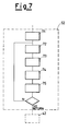
- the microprocessor 21 selects the standard route as the current route (step 71).
- the storage battery temperature is read (step 72), as is the charge present in the storage batteries (step 73).
- a calculation step (step 74) is then effected in which the residual range is calculated by simple algebraic operations starting from the value of the zero residual range point 28 and the number of kilometres corresponding, in the standard route, to the charge value read during step 73.
- the microprocessor 21 displays (step 75) the result on the display 22.
- test 76 it is checked whether the battery charger 11 is continuing to feed the charging-underway signal.
- step 72 If the result of test 76 is positive, the microprocessor 21 returns to step 72 and the cycle recommences. If the result is negative, the microprocessor 21 leaves step 52 and returns to step 42.
Landscapes
- Engineering & Computer Science (AREA)
- Life Sciences & Earth Sciences (AREA)
- Sustainable Development (AREA)
- Sustainable Energy (AREA)
- Power Engineering (AREA)
- Transportation (AREA)
- Mechanical Engineering (AREA)
- Electric Propulsion And Braking For Vehicles (AREA)
- Tests Of Electric Status Of Batteries (AREA)
- Secondary Cells (AREA)
Applications Claiming Priority (2)
| Application Number | Priority Date | Filing Date | Title |
|---|---|---|---|
| ITTO911039 | 1991-12-24 | ||
| ITTO911039A IT1250897B (it) | 1991-12-24 | 1991-12-24 | Dispositivo indicatore di autonomia per un veicolo ad accumulatori. |
Publications (2)
| Publication Number | Publication Date |
|---|---|
| EP0548748A1 true EP0548748A1 (fr) | 1993-06-30 |
| EP0548748B1 EP0548748B1 (fr) | 1995-09-13 |
Family
ID=11409839
Family Applications (1)
| Application Number | Title | Priority Date | Filing Date |
|---|---|---|---|
| EP92121304A Expired - Lifetime EP0548748B1 (fr) | 1991-12-24 | 1992-12-15 | Dispositif de signalisation de distance résiduelle pour un véhicule entraîné par un accumulateur |
Country Status (3)
| Country | Link |
|---|---|
| EP (1) | EP0548748B1 (fr) |
| DE (1) | DE69204811T2 (fr) |
| IT (1) | IT1250897B (fr) |
Cited By (13)
| Publication number | Priority date | Publication date | Assignee | Title |
|---|---|---|---|---|
| FR2714338A1 (fr) * | 1993-12-24 | 1995-06-30 | Daimler Benz Ag | Procédé et dispositif de limitation de puissance de marche. |
| EP0686257A4 (fr) * | 1992-12-31 | 1995-12-27 | ||
| WO2010033517A3 (fr) * | 2008-09-19 | 2011-03-31 | Better Place GmbH | Système et procédé de fonctionnement d'un véhicule électrique |
| US8035341B2 (en) | 2010-07-12 | 2011-10-11 | Better Place GmbH | Staged deployment for electrical charge spots |
| CN102248921A (zh) * | 2010-05-17 | 2011-11-23 | 通用汽车有限责任公司 | 用于电动车辆的多因素充电 |
| US8118147B2 (en) | 2009-09-11 | 2012-02-21 | Better Place GmbH | Cable dispensing system |
| US8164300B2 (en) | 2008-09-19 | 2012-04-24 | Better Place GmbH | Battery exchange station |
| US20120143410A1 (en) * | 2010-12-01 | 2012-06-07 | Aptera Motors, Inc. | Interactive driver system for an electric vehicle |
| US8246376B2 (en) | 2009-09-14 | 2012-08-21 | Better Place GmbH | Electrical connector with flexible blade shaped handle |
| US8454377B2 (en) | 2008-09-19 | 2013-06-04 | Better Place GmbH | System for electrically connecting batteries to electric vehicles |
| US9292976B2 (en) | 2013-10-04 | 2016-03-22 | Ford Global Technologies, Llc | Efficiency gauge for plug-in electric vehicle |
| US10304099B2 (en) | 2010-03-29 | 2019-05-28 | International Business Machines Corporation | Vehicle-to-vehicle energy market system |
| US11077768B2 (en) | 2015-07-30 | 2021-08-03 | Ford Global Technologies, Llc | Personalized range protection strategy for electrified vehicles |
Families Citing this family (7)
| Publication number | Priority date | Publication date | Assignee | Title |
|---|---|---|---|---|
| WO2009067810A1 (fr) * | 2007-11-30 | 2009-06-04 | Advanced Lithium Power Inc. | Appareil, procédé et mémoire pour destinés à améliorer le rendement et la charge de véhicules électriques hybrides |
| DE102009040966A1 (de) | 2009-09-11 | 2011-03-24 | Audi Ag | Reichweitenberechnung bei einer Vielzahl von Wegen |
| DE102009040968B4 (de) | 2009-09-11 | 2012-08-16 | Volkswagen Ag | Vorrichtung zur Darstellung einer verbleibenden Reichweite bei geplanter Rückkehr zu einem Ausgangspunkt |
| US9459110B2 (en) | 2010-01-25 | 2016-10-04 | Ford Global Technologies, Llc | Adaptive initial estimation and dynamic determination and update of distance until charge of a plug-in hybrid electric vehicle |
| EP2489990A1 (fr) | 2011-02-15 | 2012-08-22 | Brusa Elektronik AG | Dispositif d'affichage pour un véhicule électrique |
| US10065628B2 (en) | 2011-05-09 | 2018-09-04 | Ford Global Technologies, Llc | Location enhanced distance until charge (DUC) estimation for a plug-in hybrid electric vehicle (PHEV) |
| WO2020096618A1 (fr) | 2018-11-09 | 2020-05-14 | Cummins Inc. | Systèmes et procédés de commande d'électrification pour véhicules électriques |
Citations (2)
| Publication number | Priority date | Publication date | Assignee | Title |
|---|---|---|---|---|
| DE3142038A1 (de) * | 1981-10-23 | 1983-05-05 | GES Gesellschaft für elektrischen Straßenverkehr mbH, 4300 Essen | Verfahren und anordnung zur ermittlung einer restlichen fahrreichweite bei einem elektrofahrzeug |
| DE3902339A1 (de) * | 1989-01-27 | 1990-08-09 | Deta Akkumulatoren | Datenerfassungsanordnung fuer ein batteriegetriebenes fahrzeug |
-
1991
- 1991-12-24 IT ITTO911039A patent/IT1250897B/it active IP Right Grant
-
1992
- 1992-12-15 DE DE69204811T patent/DE69204811T2/de not_active Expired - Fee Related
- 1992-12-15 EP EP92121304A patent/EP0548748B1/fr not_active Expired - Lifetime
Patent Citations (2)
| Publication number | Priority date | Publication date | Assignee | Title |
|---|---|---|---|---|
| DE3142038A1 (de) * | 1981-10-23 | 1983-05-05 | GES Gesellschaft für elektrischen Straßenverkehr mbH, 4300 Essen | Verfahren und anordnung zur ermittlung einer restlichen fahrreichweite bei einem elektrofahrzeug |
| DE3902339A1 (de) * | 1989-01-27 | 1990-08-09 | Deta Akkumulatoren | Datenerfassungsanordnung fuer ein batteriegetriebenes fahrzeug |
Non-Patent Citations (1)
| Title |
|---|
| IEEE TRANSACTIONS ON INDUSTR IAL ELECTRONICS vol. IE-34, no. 4, 1987, NEW YORK US pages 447 - 456 C.C. CHAN ET AL 'COTROL STRATEGY OF PWM INVERTER DRIVE SYSTEM FOR ELECTRIC VEHICLES' * |
Cited By (17)
| Publication number | Priority date | Publication date | Assignee | Title |
|---|---|---|---|---|
| EP0686257A4 (fr) * | 1992-12-31 | 1995-12-27 | ||
| FR2714338A1 (fr) * | 1993-12-24 | 1995-06-30 | Daimler Benz Ag | Procédé et dispositif de limitation de puissance de marche. |
| US5627752A (en) * | 1993-12-24 | 1997-05-06 | Mercedes-Benz Ag | Consumption-oriented driving-power limitation of a vehicle drive |
| US8164300B2 (en) | 2008-09-19 | 2012-04-24 | Better Place GmbH | Battery exchange station |
| CN102164773A (zh) * | 2008-09-19 | 2011-08-24 | 佳境有限公司 | 用于操作电动车辆的系统和方法 |
| US8517132B2 (en) | 2008-09-19 | 2013-08-27 | Better Place GmbH | Electric vehicle battery system |
| US8454377B2 (en) | 2008-09-19 | 2013-06-04 | Better Place GmbH | System for electrically connecting batteries to electric vehicles |
| WO2010033517A3 (fr) * | 2008-09-19 | 2011-03-31 | Better Place GmbH | Système et procédé de fonctionnement d'un véhicule électrique |
| US8118147B2 (en) | 2009-09-11 | 2012-02-21 | Better Place GmbH | Cable dispensing system |
| US8246376B2 (en) | 2009-09-14 | 2012-08-21 | Better Place GmbH | Electrical connector with flexible blade shaped handle |
| US10304099B2 (en) | 2010-03-29 | 2019-05-28 | International Business Machines Corporation | Vehicle-to-vehicle energy market system |
| CN102248921A (zh) * | 2010-05-17 | 2011-11-23 | 通用汽车有限责任公司 | 用于电动车辆的多因素充电 |
| CN102248921B (zh) * | 2010-05-17 | 2014-02-12 | 通用汽车有限责任公司 | 用于电动车辆的多因素充电 |
| US8035341B2 (en) | 2010-07-12 | 2011-10-11 | Better Place GmbH | Staged deployment for electrical charge spots |
| US20120143410A1 (en) * | 2010-12-01 | 2012-06-07 | Aptera Motors, Inc. | Interactive driver system for an electric vehicle |
| US9292976B2 (en) | 2013-10-04 | 2016-03-22 | Ford Global Technologies, Llc | Efficiency gauge for plug-in electric vehicle |
| US11077768B2 (en) | 2015-07-30 | 2021-08-03 | Ford Global Technologies, Llc | Personalized range protection strategy for electrified vehicles |
Also Published As
| Publication number | Publication date |
|---|---|
| DE69204811T2 (de) | 1996-02-22 |
| DE69204811D1 (de) | 1995-10-19 |
| ITTO911039A0 (it) | 1991-12-24 |
| ITTO911039A1 (it) | 1993-06-24 |
| IT1250897B (it) | 1995-04-21 |
| EP0548748B1 (fr) | 1995-09-13 |
Similar Documents
| Publication | Publication Date | Title |
|---|---|---|
| EP0548748B1 (fr) | Dispositif de signalisation de distance résiduelle pour un véhicule entraîné par un accumulateur | |
| JP4042475B2 (ja) | 電池の劣化度算出装置および劣化度算出方法 | |
| US5703469A (en) | System for determining battery conditions | |
| US9128159B2 (en) | Plug-in charge capacity estimation method for lithium iron-phosphate batteries | |
| US6087808A (en) | System and method for accurately determining remaining battery life | |
| JPH11149944A (ja) | 組電池の電池状態診断装置、モジュール充放電器および電気車 | |
| WO2007105595A1 (fr) | Dispositif d'estimation de l'etat d'une batterie | |
| JPH06242193A (ja) | 残存容量計 | |
| EP2720055A2 (fr) | Dispositif et procédé d'estimation de la puissance chargeable/déchargeable d'un dispositif de stockage électrique | |
| KR100704944B1 (ko) | 전기 자동차용 배터리 관리 시스템 | |
| JP2001004721A (ja) | 満充電電圧修正機能付きバッテリの残存容量測定装置 | |
| EP3696012A1 (fr) | Véhicule, terminal d'information et procédé de commande de véhicule | |
| JPH0659003A (ja) | 電池残存容量計 | |
| US20230271501A1 (en) | Display system and vehicle including the same, and method of showing state of secondary battery | |
| US7015822B2 (en) | Battery capacity and usage system | |
| JP4548011B2 (ja) | 劣化度判定装置 | |
| JP2008179284A (ja) | 二次電池の劣化判定装置 | |
| US5698962A (en) | Memory effect sensitive battery monitoring apparatus for electric vehicles | |
| KR100839980B1 (ko) | 배터리팩의 충방전 제어 시스템 및 방법 | |
| US11734965B2 (en) | Method and system of calculating distance to empty of each vehicle drive mode | |
| JPH08201488A (ja) | 電気自動車用バッテリの残量表示装置 | |
| JP3200364B2 (ja) | 電気自動車の電池残存容量測定装置 | |
| JP3360446B2 (ja) | 電気自動車のバッテリ残容量表示装置 | |
| JP2002031671A (ja) | 車両のアイドリングストップ処理方法と、車両に搭載された蓄電池の残存容量測定方法、および、これらの装置 | |
| JP3634077B2 (ja) | 電池残量計 |
Legal Events
| Date | Code | Title | Description |
|---|---|---|---|
| PUAI | Public reference made under article 153(3) epc to a published international application that has entered the european phase |
Free format text: ORIGINAL CODE: 0009012 |
|
| AK | Designated contracting states |
Kind code of ref document: A1 Designated state(s): DE ES FR GB IT SE |
|
| 17P | Request for examination filed |
Effective date: 19930422 |
|
| 17Q | First examination report despatched |
Effective date: 19950215 |
|
| GRAA | (expected) grant |
Free format text: ORIGINAL CODE: 0009210 |
|
| AK | Designated contracting states |
Kind code of ref document: B1 Designated state(s): DE ES FR GB IT SE |
|
| PG25 | Lapsed in a contracting state [announced via postgrant information from national office to epo] |
Ref country code: ES Free format text: THE PATENT HAS BEEN ANNULLED BY A DECISION OF A NATIONAL AUTHORITY Effective date: 19950913 |
|
| ET | Fr: translation filed | ||
| ITF | It: translation for a ep patent filed | ||
| REF | Corresponds to: |
Ref document number: 69204811 Country of ref document: DE Date of ref document: 19951019 |
|
| PG25 | Lapsed in a contracting state [announced via postgrant information from national office to epo] |
Ref country code: SE Effective date: 19951213 |
|
| PLBE | No opposition filed within time limit |
Free format text: ORIGINAL CODE: 0009261 |
|
| STAA | Information on the status of an ep patent application or granted ep patent |
Free format text: STATUS: NO OPPOSITION FILED WITHIN TIME LIMIT |
|
| 26N | No opposition filed | ||
| REG | Reference to a national code |
Ref country code: GB Ref legal event code: IF02 |
|
| PGFP | Annual fee paid to national office [announced via postgrant information from national office to epo] |
Ref country code: GB Payment date: 20031210 Year of fee payment: 12 |
|
| PG25 | Lapsed in a contracting state [announced via postgrant information from national office to epo] |
Ref country code: GB Free format text: LAPSE BECAUSE OF NON-PAYMENT OF DUE FEES Effective date: 20041215 |
|
| PGFP | Annual fee paid to national office [announced via postgrant information from national office to epo] |
Ref country code: FR Payment date: 20041228 Year of fee payment: 13 |
|
| PGFP | Annual fee paid to national office [announced via postgrant information from national office to epo] |
Ref country code: DE Payment date: 20050222 Year of fee payment: 13 |
|
| GBPC | Gb: european patent ceased through non-payment of renewal fee |
Effective date: 20041215 |
|
| PG25 | Lapsed in a contracting state [announced via postgrant information from national office to epo] |
Ref country code: IT Free format text: LAPSE BECAUSE OF NON-PAYMENT OF DUE FEES;WARNING: LAPSES OF ITALIAN PATENTS WITH EFFECTIVE DATE BEFORE 2007 MAY HAVE OCCURRED AT ANY TIME BEFORE 2007. THE CORRECT EFFECTIVE DATE MAY BE DIFFERENT FROM THE ONE RECORDED. Effective date: 20051215 |
|
| PG25 | Lapsed in a contracting state [announced via postgrant information from national office to epo] |
Ref country code: DE Free format text: LAPSE BECAUSE OF NON-PAYMENT OF DUE FEES Effective date: 20060701 |
|
| PG25 | Lapsed in a contracting state [announced via postgrant information from national office to epo] |
Ref country code: FR Free format text: LAPSE BECAUSE OF NON-PAYMENT OF DUE FEES Effective date: 20060831 |
|
| REG | Reference to a national code |
Ref country code: FR Ref legal event code: ST Effective date: 20060831 |
|
| REG | Reference to a national code |
Ref country code: DE Ref legal event code: R082 Ref document number: 69204811 Country of ref document: DE Representative=s name: MEHLER ACHLER PATENTANWAELTE, DE Ref country code: DE Ref legal event code: R082 Ref document number: 69204811 Country of ref document: DE Representative=s name: MEHLER ACHLER PATENTANWAELTE PARTNERSCHAFT MBB, DE |