EP0548852A2 - Bandzuführungs- und aufwickelvorrichtung und Bandkassette dafür - Google Patents
Bandzuführungs- und aufwickelvorrichtung und Bandkassette dafür Download PDFInfo
- Publication number
- EP0548852A2 EP0548852A2 EP92121620A EP92121620A EP0548852A2 EP 0548852 A2 EP0548852 A2 EP 0548852A2 EP 92121620 A EP92121620 A EP 92121620A EP 92121620 A EP92121620 A EP 92121620A EP 0548852 A2 EP0548852 A2 EP 0548852A2
- Authority
- EP
- European Patent Office
- Prior art keywords
- tape
- cassette
- reel
- small size
- large size
- Prior art date
- Legal status (The legal status is an assumption and is not a legal conclusion. Google has not performed a legal analysis and makes no representation as to the accuracy of the status listed.)
- Withdrawn
Links
Images








Classifications
-
- G—PHYSICS
- G11—INFORMATION STORAGE
- G11B—INFORMATION STORAGE BASED ON RELATIVE MOVEMENT BETWEEN RECORD CARRIER AND TRANSDUCER
- G11B25/00—Apparatus characterised by the shape of record carrier employed but not specific to the method of recording or reproducing, e.g. dictating apparatus; Combinations of such apparatus
- G11B25/06—Apparatus characterised by the shape of record carrier employed but not specific to the method of recording or reproducing, e.g. dictating apparatus; Combinations of such apparatus using web-form record carriers, e.g. tape
- G11B25/066—Apparatus characterised by the shape of record carrier employed but not specific to the method of recording or reproducing, e.g. dictating apparatus; Combinations of such apparatus using web-form record carriers, e.g. tape adapted for use with containers of different sizes or configurations; adaptor devices therefor
-
- G—PHYSICS
- G11—INFORMATION STORAGE
- G11B—INFORMATION STORAGE BASED ON RELATIVE MOVEMENT BETWEEN RECORD CARRIER AND TRANSDUCER
- G11B15/00—Driving, starting or stopping record carriers of filamentary or web form; Driving both such record carriers and heads; Guiding such record carriers or containers therefor; Control thereof; Control of operating function
- G11B15/675—Guiding containers, e.g. loading, ejecting cassettes
-
- G—PHYSICS
- G11—INFORMATION STORAGE
- G11B—INFORMATION STORAGE BASED ON RELATIVE MOVEMENT BETWEEN RECORD CARRIER AND TRANSDUCER
- G11B23/00—Record carriers not specific to the method of recording or reproducing; Accessories, e.g. containers, specially adapted for co-operation with the recording or reproducing apparatus ; Intermediate mediums; Apparatus or processes specially adapted for their manufacture
- G11B23/02—Containers; Storing means both adapted to cooperate with the recording or reproducing means
- G11B23/04—Magazines; Cassettes for webs or filaments
- G11B23/08—Magazines; Cassettes for webs or filaments for housing webs or filaments having two distinct ends
- G11B23/087—Magazines; Cassettes for webs or filaments for housing webs or filaments having two distinct ends using two different reels or cores
Definitions
- This invention relates to a tape supplying and taking up apparatus and tape cassettes for use therewith, and more particularly is directed to a tape supplying and taking up apparatus for selective use with two types of cassettes having different large and small sizes.
- a tape supplying and taking up apparatus is known in which two types of tape cassettes of different large and small sizes can be used.
- One example of a conventional tape supplying and taking up apparatus of the type mentioned is a tape supplying and taking up apparatus employed in certain video tape recorders of the so-called compatible type in which a standard tape cassette for the so-called VHS system and a small size tape cassette, commonly called a C-cassette, can be selectively used.
- a VHS standard tape cassette and a C-cassette have certain structural features in common, in that the tape reels and the access holes formed in the bottom wall of the cassette casing for exposing reel spindle engaging holes of the tape reels have the same diameters in both cases.
- the diameters of the tape reels and of the access holes are determined by the need to maintain accurate rotation of the reels in a VHS standard tape cassette.
- the tape reels are of unnecessarily large diameter so that space is wasted within the cassette casing and only undesirably limited amounts of tape can be accommodated in the C-cassette.
- the relatively large diameter tape reels require correspondingly large access holes in the bottom wall of the cassette casing, and such large access holes in the bottom wall of the small C-cassette casing are not readily closed by means of a shutter of the kind used on tape cassettes for a digital audio tape recorder.
- a tape supplying and taking up apparatus capable of receiving two types of tape cassettes of large and small sizes, respectively, which each contain a pair of tape reels having a tape wound on the tape reels with a tape portion extending therebetween, comprises: a chassis; large and small size tape cassette locating means on the chassis for selectively locating the tape cassettes in respective operative positions thereon; and a pair of reel spindles mounted on the chassis for engaging the pair of tape reels of either one of the large and small size tape cassettes when in its respective operative position, each of the reel spindles having a large size cassette receiving portion for receiving a respective tape reel of a large size tape cassette thereon and a small size cassette receiving portion for receiving a respective tape reel of a small size tape cassette thereon, the large size cassette receiving portion and the small size cassette receiving portion of each of the reel spindles being disposed in coaxial relationship, with the small size cassette receiving portion of each of reel spindle having a small diameter and being disposed at a higher position
- the tape reels for the large and small size tape cassettes may be formed with different sizes since the receiving portions of the reel spindles for the large and small size tape cassettes are formed coaxially but are different in diameter and height or vertical position from each other.
- the tape reels of a large size tape cassette can be made of a size required for a desired degree of accuracy in rotation which conforms to that size.
- the tape reels of a small size tape cassette may be made in a suitable size smaller than the tape reels of a large size tape cassette, and consequently, the utilization of space in the casing and the appearance of the small size tape cassette can be improved.
- a small size tape cassette for use with a tape supplying and take up apparatus as defined above, and in which the diameter of the lower end of a reel spindle engaging hole formed in a reel hub of each of the tape reels is smaller than the outer diameter of the small size cassette receiving portion of each of the reel spindles.
- a large size tape cassette for use with a tape supplying and taking up apparatus as defined above, and in which a reel spindle engaging hole formed in a reel hub of each of the tape reels has a lower end or escape portion with a diameter larger than the outer diameter of the small size cassette receiving portion of the reel spindle but smaller than the outer diameter of the large size cassette receiving portion, and such escape portion is higher than the height of the small size cassette receiving portion of the reel spindle.
- the present invention will now be described in detail below in connection with a preferred embodiment thereof in which it is applied to a video tape recorder of the compatible type, that is, capable of use with large size and small size tape cassettes.
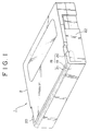
- a tape cassette 1 of a large size which includes a cassette casing 2 in the form of a flattened box having a transversely elongated rectangular shape as viewed in plan.
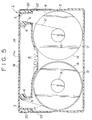
- the casing 2 has a pair of tape exits 3 (Figs. 2 and 5) formed at the opposite end portions of the front of the casing which further has a mouth portion 4 between the tape exits 3 opening forwardly and downwardly of the cassette casing 2.
- a pair of upright cylindrical tape guides 5 are provided between the tape exits 3 and the mouth portion 4.
- Each of the cylindrical tape guides 5 has a coaxial positioning hole 6 opening at the bottom of the cassette casing 2.
- a pair of access holes 7 are formed in laterally spaced relation in a bottom wall 8 of the cassette casing 2 for exposing reel spindle engaging holes formed in hubs of tape reels, which will be hereinafter described.
- a pair of light introducing holes 9 are formed in wall portions of the cassette casing 2 defining the opposite sides of the mouth portion 4.
- Another pair of light introducing holes 10 are formed in front end portions of the opposite left and right side walls of the cassette casing 2 and are aligned with the holes 9.
- an escape hole 11 is formed in the bottom wall 8 at a position a little to the rear of a central position between the access holes 7.
- each of the tape reels 12 includes a cylindrical reel hub 13, and a pair of upper and lower flanges 14 and 15 formed or mounted integrally at the opposite upper and lower end portions of the reel hub 13.
- the reel hub 13 extends, at the lower end portion 13a thereof, a little downwardly from the lower flange 15.
- the extent of the lower extension 13a of the reel hub 13 is equal to or smaller than the thickness of the bottom wall 8 of the cassette casing 2.
- the lower extension 13a has an outer diameter smaller than the inner diameter of the access holes 7 of the cassette casing 2.
- the reel hub 13 of each of the tape reels 12 has a coaxial reel spindle engaging hole 16 therein opening at the lower end thereof.
- the reel spindle engaging hole 16 is increased in diameter at a lower end portion 16a thereof. Details of the dimensions of the increased diameter portion 16a will be hereinafter described.
- a magnetic tape 17 is fixed at its opposite ends to, and wound on the reel hubs 13 of the tape reels 12.
- the tape reels 12 are rotatably accommodated in the cassette casing 2 with the lower extensions 13a of the reel hubs 13 thereof being loosely positioned within the holes 7 of the cassette casing 2.
- the magnetic tape 17 between the reels 12 is led out from the casing 2 through the tape exits 3 to the outside of the cassette casing 2, and such led out portion of the magnetic tape 17 is positioned by the spindles 5 in a straight run 17a extending across the front of the cassette casing 2.
- a front lid 18 is supported for pivotal motion at the front portion of the cassette casing 2.
- the front lid 18 is formed as a unitary member and has a front face portion 19 in the form of a laterally elongated plate which, in the closed position of the lid 15 (Fig. 1), covers the front of the cassette casing 2, a pair of side portions 20 extending rearwardly from the opposite left and right ends of the front face portion 19, and an upper face portion 21 having a front edge contiguous to an upper edge of the front face portion 19 and a pair of left and right side edges contiguous to upper edges of the said portions 20.
- the side portions 20 of the front lid 18 are supported for pivotal motion on the left and right sides of a front end portion of the cassette casing 2.
- the front lid 18 is normally biased in a closing direction by a spring means (not shown) so that it is positioned, when the large size tape cassette 1 is not in use, in its closed position shown in Fig. 1 and at which the front face portion 19 covers over the front side of the portion of the magnetic tape 17 led out to the outside of the cassette casing 2.
- the front lid 18 is pivoted by a lid opener, which will be hereinafter described, to its opened position at which it exposes the front side of the magnetic tape run 17a, as seen in Fig. 2.
- a shutter 22 is supported for sliding movement in the forward and rearward directions on the bottom of the cassette casing 2 and is normally biased forwardly by a spring means (not shown), to the position shown on Fig. 3, similarly to a conventional tape cassette for use in a digital audio tape recorder.
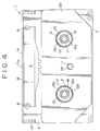
- the shutter 22 has a pair of reel spindle access holes 23 (Figs. 3 and 4) in laterally spaced relationship therein.
- the shutter 22 further has a single exposing hole 24 formed therein between holes 23.
- the shutter 22 When the shutter 22 is at the front end of a range of movement thereof, that is, at its closed position (Fig. 3), the reel spindle access holes 23 and the exposing hole 24 formed therein are displaced from the access holes 7 and the escape hole 11 of the cassette casing 2. Consequently, the access holes 7 and the escape hole 11 of the cassette casing 2 are closed by the shutter 22. Further, the bottom of the mouth portion 4 of the cassette casing 2 is closed by the front end portion of the shutter 22 as seen in Fig.3. Accordingly, the mouth portion 4 is closed at the front thereof by the front lid 18 and at the bottom thereof by the shutter 22 and thus presents a substantially sealed condition wherein the tape 17 is protected completely against contaminants from outside the cassette.
- the shutter 22 When the tape cassette 1 is operatively positioned in a video tape recorder, the shutter 22 is retracted to its opened position similarly as in a tape cassette for a digital audio tape recorder.
- the reel spindle access holes 23 of the shutter 22 coincide with the respective holes 7 of the cassette casing 2 so that the reel spindle engaging holes 16 of the tape reels 12 are individually exposed to the outside through the aligned holes 7 and 23.
- the exposing hole 24 of the shutter 22 coincides with the escape hole 11 of the cassette casing 2 so that the escape hole 11 is exposed to the outside as seen from Fig. 4.
- the small size tape cassette is generally denoted at 25 and has a size about two fifths that of the large size tape cassette 1 as viewed in plan.
- the small size tape cassette 25 includes a cassette casing 26 which is in the form of a flattened box having a transversely elongated rectangular shape as viewed in plan and further having a pair of tape exits 27 formed at the opposite end portions of the front thereof.
- the cassette casing 26 has a lateral or leftward and rightward dimension substantially equal to the depth or forward and backward dimension of the cassette casing 2 of the large size tape cassette 1.
- the cassette casing 26 has a depth or forward and backward dimension which is substantially two fifths of the lateral or leftward and rightward dimension of the cassette casing 2. Moreover, the lateral or leftward and rightward dimension of the cassette casing 26 is smaller than the lateral or leftward and rightward dimension of the mouth portion 4 of the large size tape cassette 1.
- a mouth portion 28 is formed at the front of the cassette casing 26 between the tape exits 27 and opens forwardly and downwardly of the cassette casing 26.
- the mouth portion 28 provides access to the tape for a tape drawing out member (not shown).
- a pair of upright cylindrical tape guides 29 are provided at the tape exits 27 adjacent the mouth portion 28.
- Each of the cylindrical tape guides 29 has a coaxial positioning hole 30 (Figs. 9 and 10) opening at the bottom of the cassette casing 26.
- the distance between the positioning holes 30 is significantly smaller than the lateral or leftward and rightward dimension of the mouth portion 4 of the cassette casing 2 of the large size tape cassette 1.
- a pair of access holes 31 are formed in laterally spaced relationship in a bottom wall 32 of the cassette casing 26 for exposing reel spindle engaging holes formed in hubs of tape reels, as will be hereinafter described.
- a pair of light introducing holes 33 are formed in wall portions of the cassette casing 26 defining the opposite sides of the mouth portion 28.
- Another pair of light introducing holes 34 are formed in front end portions of the opposite left and right side walls of the cassette casing 26 so as to be aligned with the holes 33.
- a pair of tape reels 35 are rotatably accommodated in the cassette casing 26.
- Each of the tape reels 35 is shown, particularly on Fig. 17B, to include a cylindrical reel hub 36, and a pair of upper and lower flanges 37 and 38 formed or mounted integrally at the upper and lower end portions of the reel hub 36.
- the reel hub 36 extends, at the lower end portion 36a thereof, a little downwardly from the lower flange 38.
- the extent of such downward extension 36a of the reel hub 36 is equal to or smaller than the thickness of the bottom wall 32 of the cassette casing 26.
- the lower extension 36a has an outer diameter smaller than the inner diameter of each of the access holes 31 of the cassette casing 26.
- the reel hub 36 of each of the tape reels 35 has a reel spindle engaging hole 39 opening at the lower end thereof.
- a magnetic tape 40 is fixed at its opposite ends to, and wound on the reel hubs 36 of the tape reels 35.
- the tape reels 35 are accommodated for rotation in the cassette casing 26 with the lower extensions 36a of the reel hubs 36 thereof loosely positioned within the holes 31 of the cassette casing 26.
- the magnetic tape 40 between the reels 35 is led out from the casing 26 through the tape exits 27 to the outside of the cassette casing 26, and such led out portion of the magnetic tape 40 is positioned by the guides 29 in a straight run 40a extending across the front of the cassette casing 26.
- a front lid 41 is supported for pivotal motion at the front of the cassette casing 26.
- the front lid 41 is formed as a unitary member and has a front face portion 42 in the form of a laterally elongated plate which, in the closed position of the lid 41 (Fig. 6), covers the front of the cassette casing 26, a pair of side portions 43 extending rearwardly from the opposite left and right ends of the front face portion 42, and an upper face portion 44 having a front edge contiguous to an upper edge of the front face portion 42 and a pair of left and right side edges contiguous to upper edges of the side portions 43.
- the side portions 43 of the front lid 41 are suitably supported for pivotal motion on the left and right sides of a front end portion of the cassette casing 26.
- the front lid 41 is normally biased in a closing direction by a spring means (not shown) so that it is positioned, when the small size tape cassette 25 is not in use, in its closed position shown in Fig. 6 at which the front face portion 42 covers the front side of the run 40a of the magnetic tape 40 led out to the outside of the cassette casing 26.
- the front lid 41 is pivoted by another lid opener, which will be hereinafter described, to its opened position at which it exposes the front side of the magnetic tape run 40a as seen in Fig. 7.
- a shutter 45 is supported for sliding movement in the forward and rearward directions on the bottom of the cassette casing 26 and is normally biased forwardly by a spring means (not shown) similarly to a conventional tape cassette for use in a digital audio tape recorder.
- the shutter 45 has a pair of reel spindle access holes 46 (Figs. 8 and 9) in laterally spaced relationship therein.
- the shutter 45 When the shutter 45 is at the front end of a range of movement thereof, that is, at its closed position (Fig. 8) the reel spindle access holes 46 formed in the shutter 45 are displaced from the access holes 31 of the cassette casing 26. Consequently, the holes 31 of the cassette casing 26 are closed by the shutter 45. Further, in the closed position of the shutter 45, the bottom of the mouth portion 28 of the cassette casing 26 is closed by the front end portion of the shutter 45, as seen in Fig. 8. Accordingly, the mouth portion 28 is closed at the front thereof by the front lid 41 and at the bottom thereof by the shutter 45 and there is no access from the outside to the interior of the casing 26 through the mouth portion 28.
- the shutter 45 When the tape cassette 25 is loaded into a video tape recorder, the shutter 45 is retracted to its opened portion similarly to a tape cassette for a digital audio tape recorder.
- the reel spindle access holes 46 of the shutter 45 coincide individually with the access holes 31 of the cassette casing 26 so that the reel spindle engaging holes 39 of the tape reels 35 are exposed to the outside through the aligned access holes 31 and 46.
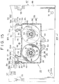
- FIG. 11 to 16 there is shown a deck portion of a video tape recorder according to the present invention in which the tape cassettes 1 and 25 described above can be selectively used.
- the illustrated video tape recorder is generally denoted at 47 and includes a chassis 48 on which a pair of reel spindle supporting arms 49 are supported for individual pivotal motion about upright support shafts 50 which are mounted in laterally spaced relationship at mid portions of the rear half of the chassis 48.
- Upstanding reel spindles 51 are rotatably supported at ends of the reel spindle supporting arms 49 remote from support shafts 50.
- Each of the reel spindles 51 has a disk-shaped reel receiving portion 52, a gear portion 53 formed integrally on a lower face of the receiving portion 52, and a reel engaging shaft 54 extending upwardly from the top end of the receiving portion 52.
- the receiving portion 52 of each reel spindle 51 is stepped to include a relatively large diameter lower portion 52a for receiving a large size cassette, and a relatively small diameter upper portion 52b for receiving a small size cassette.
- the small size cassette receiving portion 52b extends above and is smaller in diameter than the large size cassette receiving portion 52a.
- the inner diameter of the increased diameter portion 16a of the reel spindle engaging hole 16 of each tape reel 12 of the large size tape cassette 1 is larger than the outer diameter of the small size cassette receiving portion 52b of the receiving portion 52 of the reel spindle 51 hut smaller than the outer diameter of the large cassette receiving portion 52a. Further, the height of the increased diameter portion 16a is made a little greater than the height of the small size cassette receiving portion 52b above the large size cassette receiving portion 52a.
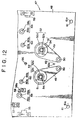
- the reel spindle supporting arms 49 are mounted for pivotal movements between large size cassette driving positions shown in Fig. 11 and small size cassette driving positions shown in Fig. 12.
- a respective driving gear (not shown) is engagable with the gear 53 of either one of the reel spindles 51 for rotatably driving the same.
- a pair of light receiving elements 55 (Figs. 11, 12, 13, and 15) are disposed on the left and right end portions of the chassis 48 at positions displaced a little forwardly from the center in the forward and backward directions.
- a light emitting element 56 is disposed at a central position between and in lateral alignment with the light receiving elements 55.
- An upstanding lid opener 57 for a large size tape cassette 1 is disposed on the chassis 48 proximate to the light receiving element 55 which is on the left end portion of the chassis in Fig. 11.
- Another upstanding lid opener 58 for a small size tape cassette 25 is disposed on the chassis at a position displaced laterally from the lid opener 57 toward the light emitting element 56.
- a pressing pin 58a extends laterally inward from an upper end portion of the lid opener 58 for cooperation with a small tape cassette 25 as hereinafter described.
- a pair of upstanding positioning pins 59 for a large size tape cassette 1 are provided on the chassis 48.
- Each of the positioning pins 59 has a cylindrical base or main portion 59a and a conical inserting portion 59b extending from an upper end face of the main portion 59a.
- the upper end face of the main portion 59a of each positioning pin 59 serves as a reference surface for establishing a vertical position of the cassette while position of the latter in a horizontal direction is performed by the inserting portion 59b.
- One of the positioning pins 59 is located between the lid openers 57 and 58 and is displaced from a mid-position therebetween a little toward the lid opener 58 for a small size tape cassette.
- the other positioning pin 59 is located symmetrically about the median of the chassis 48 relative to the first described positioning pin 59.
- a pair of upstanding positioning pins 60 for a small size tape cassette 25 are also provided on the chassis 48.
- Each of the positioning pins 60 has a cylindrical base or main portion 60a and a conical inserting portion 60b extending from an upper end face of the main portion 60a.
- the upper end face of the main portion 60a of each positioning pin 60 serves as a reference surface for establishing a vertical position of the cassette 25 while positioning of the latter in a horizontal direction is performed by the inserting portion 60b.
- One of the positioning pins 60 is located adjacent the lid opener 58 and is displaced a small distance therefrom toward the light emitting element 56.
- the other positioning pin 60 is located symmetrically about the median of the chassis 48 relative to the last described positioning pin 60.
- a pair of upright vertical position defining pins 61 for a large size tape cassette are mounted on the chassis 48 at positions displaced substantially rearwardly from the positioning pins 59 and laterally outward relative to the latter.
- Each of the vertical position defining pins 61 has an upper end face 61a which serves as a reference surface.
- An upright vertical position defining pin 62 for the small size tape cassette 25 is mounted at a position on the chassis 48 displaced a little forwardly from a mid position between the support shafts 50.
- the vertical position defining pin 62 has an upper end face 62a which serves as a reference surface.
- the top end faces of the main portions 59a of the positioning pins 59 lie substantially in the same horizontal plane as the reference faces 61a of the vertical position defining pins 61, and the top end faces of the main portions 60a of the positioning pins 60 lie substantially in the same horizontal plane as the reference face 62a of the vertical position defining pin 62.
- the horizontal plane containing the top end faces of the main portions 60a of the positioning pins 60 and the reference face 62a of the vertical position defining pin 62 is positioned a little higher than the horizonal plane containing the top end faces of the main portions 59a of the positioning pins 59 and the reference faces 61a of the vertical position defining pins 61.
- the small size tape cassette 25 when in its operative position on the chassis 48, the small size tape cassette 25 is positioned with its under surface at a higher level than the under surface of the large size tape cassette 1 in its operative position and, accordingly, as is apparent from Figs. 14 and 16, the bottom wall 8 of the large size tape cassette 1 is formed with a greater thickness than the bottom wall 32 of the small size tape cassette 25.
- the video tape recorder 47 further includes various members, such as, a head drum, a tape drawing out member, tape guides and a tension regulator, those members may be conventional and form no part of the present invention so as to justify their omission form the drawings and this description.
- a small size tape cassette 25 is initially inserted horizontally into a cassette holder (not shown) of the video tape recorder 47, and, in the course of such insertion, the shutter 45 is conventionally moved to its opened position similarly to a tape cassette for a digital audio tape recorder. Further, the small size tape cassette 25 inserted in the cassette holder is conventionally detected by detecting means (note shown) and, in response to such detection, the reel spindle supporting arms 49 are suitably pivoted to their small size cassette driving positions (Figs. 12 and 15).
- the cassette holder is conventionally moved downwardly until the tape cassette 25 is moved therewith toward its mounted operative position at which the reel engaging shafts 54 of the reel spindles 51 are engaged in the reel spindle engaging holes 39 of the tape reels 35 of the tape cassette 25.
- the lower ends of the reel hubs 36 of the tape reels 35 are seated on the small size cassette receiving portions 52b of the receiving portions 52 of the reel spindles 51 (Fig. 16).
- the lower flanges 38 of the tape reels 35 are raised slightly above the inner surface of the bottom wall 32 of the cassette casing 26.
- the conical portions 60b of the positioning pins 60 are inserted into the positioning holes 30 so that the tape cassette 25 is accurately positioned in the horizontal direction.
- the upper end faces of the main portions 60a of the positioning pins 60 are abutted by circumferential edge portions of the openings of the positioning holes 30 while the reference surface 62a of the vertical position defining pin 62 is abutted by the bottom surface of the bottom wall 32 of the cassette casing 26, thereby defining the vertical position of the tape cassette 25.
- the magnetic tape 40 is conventionally withdrawn from the cassette casing 26 and is loaded about a guide drum (not shown) so that a reproducing operation or a recording operation of the video tape recorder can be performed.
- the light emitting element 56 is positioned within the mouth portion 28 of the tape cassette 25, and the light introducing holes 33 and 34 of the tape cassette 25 are aligned with a straight light path interconnecting the light emitting element 56 and the light receiving elements 55.
- a transparent portion at an end of the magnetic tape 40 is interposed in the light path, so that light from the light emitting element 56 is received by one of the light receiving elements 55, thereby detecting the end of the magnetic tape 40.
- the large size tape cassette 1 is initially inserted horizontally into the cassette holder (not shown) and, in the course of such insertion, the shutter 22 is suitably moved to its opened position. Further, the large size tape cassette 1 thus inserted in the cassette holder is detected, and, in response to such detection, the reel spindle supporting arms 49 are suitably pivoted to their large size cassette driving positions (Figs. 11 and 13).
- the cassette holder is moved downwardly until the tape cassette 1 is moved therewith toward its mounted operative position at which the reel engaging shafts 54 of the reel spindles 51 are engaged in the reel spindle engaging holes 16 of the tape reels 12 of the tape cassette 1.
- the lower ends of the reel hubs 13 of the tape reels 12 are seated on the large size cassette receiving portions 52a of the receiving portions 52 of the reel spindles 51 (Fig. 14).
- the final increment of downward movement of the casing 2 with the cassette holder raises the lower flanges 15 of the tape reels 12 slightly above the inner surface of the bottom wall 8 of the cassette casing 2.
- the small size cassette receiving portions 52b of the receiving portions 52 of the reel spindles 51 are positioned within the increased diameter portions 16a of the reel spindle engaging holes 16 of the tape reels 12 of the large size tape cassette 1.
- an upper edge of the lid opener 57 is abutted by a lower edge of the front face portion 19 of the front lid 18 at a position near a corresponding one of the side portions 20, and then, as the cassette holder and hence the tape cassette 1 are further moved downwardly, the upper edge of the lid opener 57 relatively pushes the lower edge of the front face portion 19 of the front lid 18 upwardly so that the front lid 18 is moved to its opened position (Fig. 14).
- the conical portions 59b of the positioning pins 59 are inserted into the positioning holes 6 so that the tape cassette 1 is accurately positioned in the horizontal direction, and the upper end faces of the main portions 59a of the positioning pins 59 are abutted by circumferential edge portions of the openings of the positioning holes 6 while the reference surfaces 61a of the vertical position defining pins 61 are abutted by the bottom face of the bottom wall 8 of the cassette casing 2, thereby accurately defining or establishing the vertical position of the tape cassette 1.
- the lid opener 58 for a small size tape cassette, the positioning pins 60 for a small size tape cassette and the light emitting element 56 are positioned within the mouth portion 4 of the large size tape cassette 1. Further, the light introducing holes 9 and 10 of the tape cassette 1 are aligned with the straight light path interconnecting the light emitting element 56 and the light receiving elements 55. Furthermore, the vertical position defining pin 62 for the small size tape cassette 25 is received, at an upper end portion thereof, in the escape hole 11 of the large size tape cassette 1. Accordingly, there is no trouble even if the reference face 62a of the position defining pin 62 is at a higher position than the lower face of the bottom wall 8 of the large size tape cassette 1.
- the magnetic tape 40 is conventionally withdrawn from cassette casing 2 and loaded about a guide drum or the like so that a reproducing operation or a recording operation of the video tape recorder can be performed.
Landscapes
- Packaging Of Annular Or Rod-Shaped Articles, Wearing Apparel, Cassettes, Or The Like (AREA)
- Unwinding Webs (AREA)
Applications Claiming Priority (2)
| Application Number | Priority Date | Filing Date | Title |
|---|---|---|---|
| JP358034/91 | 1991-12-27 | ||
| JP03358034A JP3094611B2 (ja) | 1991-12-27 | 1991-12-27 | テープ供給巻取装置及び該装置に使用するテープカセット |
Publications (2)
| Publication Number | Publication Date |
|---|---|
| EP0548852A2 true EP0548852A2 (de) | 1993-06-30 |
| EP0548852A3 EP0548852A3 (en) | 1994-11-17 |
Family
ID=18457200
Family Applications (1)
| Application Number | Title | Priority Date | Filing Date |
|---|---|---|---|
| EP19920121620 Withdrawn EP0548852A3 (en) | 1991-12-27 | 1992-12-18 | Tape supplying and taking up apparatus and tape cassettes for use therewith |
Country Status (6)
| Country | Link |
|---|---|
| US (1) | US5316236A (de) |
| EP (1) | EP0548852A3 (de) |
| JP (1) | JP3094611B2 (de) |
| KR (1) | KR100248679B1 (de) |
| AU (1) | AU659898B2 (de) |
| CA (1) | CA2086312C (de) |
Cited By (3)
| Publication number | Priority date | Publication date | Assignee | Title |
|---|---|---|---|---|
| EP0633574A3 (de) * | 1993-07-07 | 1995-02-22 | Sony Corp | Aufnahme- und Wiedergabegerät. |
| WO2000025314A1 (en) * | 1998-10-27 | 2000-05-04 | Fuji Photo Film Co., Ltd. | Magnetic tape cassette |
| EP1221698A4 (de) * | 1999-09-20 | 2008-03-05 | Fujifilm Corp | Magnetbandkassette |
Families Citing this family (12)
| Publication number | Priority date | Publication date | Assignee | Title |
|---|---|---|---|---|
| JP3087802B2 (ja) * | 1993-04-30 | 2000-09-11 | キヤノン株式会社 | 磁気記録再生装置 |
| KR960016897B1 (ko) * | 1994-01-07 | 1996-12-26 | 엘지전자 주식회사 | 비데오 카셋트 레코더용 릴테이블 이송장치 |
| JP3166473B2 (ja) * | 1994-03-15 | 2001-05-14 | ソニー株式会社 | 記録再生装置 |
| KR0183711B1 (ko) * | 1995-05-18 | 1999-04-15 | 김광호 | 자기 기록/재생기의 릴 테이블 이동 메카니즘 |
| KR0170335B1 (ko) * | 1995-05-18 | 1999-04-15 | 김광호 | 자기 기록/재생기의 테이프 카세트 안착 메카니즘 |
| KR0170334B1 (ko) * | 1995-05-18 | 1999-04-15 | 김광호 | 자기 기록/재생기의 릴 브레이크 메카니즘 |
| KR0148317B1 (ko) * | 1995-08-21 | 1998-12-15 | 배순훈 | Vcr의 릴록해제장치 |
| KR100412752B1 (ko) * | 1995-08-22 | 2004-04-13 | 산요덴키가부시키가이샤 | 이동가능한릴대를구비한자기기록재생장치 |
| KR0170718B1 (ko) * | 1995-12-27 | 1999-04-15 | 김광호 | 테이프 레코더의 릴테이블 이동메카니즘 |
| KR100224619B1 (ko) * | 1997-01-22 | 1999-10-15 | 윤종용 | 자기기록재생기의 테이프 카세트 리드 오픈장치 |
| GB2407203B (en) * | 2003-10-16 | 2007-11-07 | Hitachi Maxell | Tape cartridge end detection compatible with different tape widths |
| JP2008176886A (ja) * | 2007-01-19 | 2008-07-31 | Fujifilm Corp | テープリール、記録テープカートリッジ、マシンリール及びドライブ装置 |
Family Cites Families (10)
| Publication number | Priority date | Publication date | Assignee | Title |
|---|---|---|---|---|
| US3877656A (en) * | 1972-03-03 | 1975-04-15 | Canon Kk | Reel supporting device in instruments loaded with reels |
| US4173319A (en) * | 1975-12-13 | 1979-11-06 | Victor Company Of Japan, Limited | Magnetic tape cassette |
| JPS58131480U (ja) * | 1982-02-26 | 1983-09-05 | 松下電器産業株式会社 | テ−プカセツト |
| JPS60187982A (ja) * | 1984-03-07 | 1985-09-25 | Sony Corp | テ−プカセット |
| DE3432831C1 (de) * | 1984-09-06 | 1985-11-14 | Feinwerk Elektronik GmbH, 8000 München | Kassetten-Tonbandgeraet |
| DE3510874A1 (de) * | 1985-03-26 | 1986-10-09 | Joachim 5303 Bornheim Gawanka | Vorrichtung zur mehrfachnutzung der endabtastung eines kassettenbandes |
| JPS6222782U (de) * | 1985-07-26 | 1987-02-12 | ||
| JPH0648588Y2 (ja) * | 1985-12-18 | 1994-12-12 | ソニー株式会社 | カセツト位置決め装置 |
| DE3643457A1 (de) * | 1986-12-19 | 1988-06-23 | Agfa Gevaert Ag | Magnetbandcassette |
| JPH02285546A (ja) * | 1989-04-27 | 1990-11-22 | Sony Corp | リール台シフト装置の移動台位置決め機構 |
-
1991
- 1991-12-27 JP JP03358034A patent/JP3094611B2/ja not_active Expired - Fee Related
-
1992
- 1992-12-16 US US07/991,266 patent/US5316236A/en not_active Expired - Lifetime
- 1992-12-18 EP EP19920121620 patent/EP0548852A3/en not_active Withdrawn
- 1992-12-23 KR KR1019920025261A patent/KR100248679B1/ko not_active Expired - Fee Related
- 1992-12-23 AU AU30363/92A patent/AU659898B2/en not_active Ceased
- 1992-12-24 CA CA002086312A patent/CA2086312C/en not_active Expired - Fee Related
Cited By (4)
| Publication number | Priority date | Publication date | Assignee | Title |
|---|---|---|---|---|
| EP0633574A3 (de) * | 1993-07-07 | 1995-02-22 | Sony Corp | Aufnahme- und Wiedergabegerät. |
| US5992781A (en) * | 1993-07-07 | 1999-11-30 | Sony Corporation | Indirect drive mechanism for recording and reproducing apparatus capable of accomodating different size cassettes |
| WO2000025314A1 (en) * | 1998-10-27 | 2000-05-04 | Fuji Photo Film Co., Ltd. | Magnetic tape cassette |
| EP1221698A4 (de) * | 1999-09-20 | 2008-03-05 | Fujifilm Corp | Magnetbandkassette |
Also Published As
| Publication number | Publication date |
|---|---|
| JPH05182302A (ja) | 1993-07-23 |
| US5316236A (en) | 1994-05-31 |
| JP3094611B2 (ja) | 2000-10-03 |
| KR100248679B1 (ko) | 2000-03-15 |
| AU3036392A (en) | 1993-07-01 |
| KR930014431A (ko) | 1993-07-23 |
| AU659898B2 (en) | 1995-06-01 |
| CA2086312C (en) | 2001-10-16 |
| CA2086312A1 (en) | 1993-06-28 |
| EP0548852A3 (en) | 1994-11-17 |
Similar Documents
| Publication | Publication Date | Title |
|---|---|---|
| US5316236A (en) | Tape supplying and taking up apparatus and tape cassettes for use therewith | |
| CA1168642A (en) | Miniature type tape cassette | |
| US4418373A (en) | Tape cassette | |
| US4664337A (en) | Cassette tape recording and/or reproducing apparatus accommodating cassettes of different sizes | |
| US4173319A (en) | Magnetic tape cassette | |
| US3900171A (en) | Tape cassette | |
| CA1056501A (en) | Tape cassette | |
| EP0438144A2 (de) | Bandkassette | |
| EP0473437B1 (de) | Bandkassette | |
| GB2121763A (en) | Adapter for a miniature type tape cassette | |
| US5926351A (en) | Tape cartridge with irregular surface sections for reducing slippage between cartridge and gripping arms and debris production | |
| US4504876A (en) | Miniature type tape cassette | |
| US4485990A (en) | Recording tape cassette | |
| US5228636A (en) | Tape cassette | |
| US5495374A (en) | Automatic loader mechanism for magnetic tape cartridge with tension control | |
| US5537279A (en) | Tape cassette and magnetic recording/reproducing device | |
| JP3550857B2 (ja) | テープカートリッジ | |
| JP3304339B2 (ja) | テープカセット | |
| JPH0621106Y2 (ja) | 磁気テープカセット | |
| JP3200987B2 (ja) | 記録再生装置及びテープカセット | |
| JP2508970B2 (ja) | テ―プカセット | |
| JPH09161441A (ja) | テープカセット | |
| JPH05182323A (ja) | テープ供給巻取装置及び該装置に使用するテープカセット | |
| JP2546193B2 (ja) | カセット | |
| JP2629431B2 (ja) | テープカセット |
Legal Events
| Date | Code | Title | Description |
|---|---|---|---|
| PUAI | Public reference made under article 153(3) epc to a published international application that has entered the european phase |
Free format text: ORIGINAL CODE: 0009012 |
|
| AK | Designated contracting states |
Kind code of ref document: A2 Designated state(s): DE ES FR GB IT NL |
|
| PUAL | Search report despatched |
Free format text: ORIGINAL CODE: 0009013 |
|
| AK | Designated contracting states |
Kind code of ref document: A3 Designated state(s): DE ES FR GB IT NL |
|
| 17P | Request for examination filed |
Effective date: 19950419 |
|
| 17Q | First examination report despatched |
Effective date: 19960111 |
|
| STAA | Information on the status of an ep patent application or granted ep patent |
Free format text: STATUS: THE APPLICATION IS DEEMED TO BE WITHDRAWN |
|
| 18D | Application deemed to be withdrawn |
Effective date: 19960723 |