EP0548908A2 - Kraftstoff-Einspritzdüsen-Anordnung zur Verwendung in einer Gasturbinen-Brennkammer - Google Patents
Kraftstoff-Einspritzdüsen-Anordnung zur Verwendung in einer Gasturbinen-Brennkammer Download PDFInfo
- Publication number
- EP0548908A2 EP0548908A2 EP92121790A EP92121790A EP0548908A2 EP 0548908 A2 EP0548908 A2 EP 0548908A2 EP 92121790 A EP92121790 A EP 92121790A EP 92121790 A EP92121790 A EP 92121790A EP 0548908 A2 EP0548908 A2 EP 0548908A2
- Authority
- EP
- European Patent Office
- Prior art keywords
- fuel jetting
- jetting nozzle
- fuel
- air
- swirling
- Prior art date
- Legal status (The legal status is an assumption and is not a legal conclusion. Google has not performed a legal analysis and makes no representation as to the accuracy of the status listed.)
- Granted
Links
Images





Classifications
-
- F—MECHANICAL ENGINEERING; LIGHTING; HEATING; WEAPONS; BLASTING
- F23—COMBUSTION APPARATUS; COMBUSTION PROCESSES
- F23D—BURNERS
- F23D14/00—Burners for combustion of a gas, e.g. of a gas stored under pressure as a liquid
- F23D14/20—Non-premix gas burners, i.e. in which gaseous fuel is mixed with combustion air on arrival at the combustion zone
- F23D14/22—Non-premix gas burners, i.e. in which gaseous fuel is mixed with combustion air on arrival at the combustion zone with separate air and gas feed ducts, e.g. with ducts running parallel or crossing each other
- F23D14/24—Non-premix gas burners, i.e. in which gaseous fuel is mixed with combustion air on arrival at the combustion zone with separate air and gas feed ducts, e.g. with ducts running parallel or crossing each other at least one of the fluids being submitted to a swirling motion
-
- F—MECHANICAL ENGINEERING; LIGHTING; HEATING; WEAPONS; BLASTING
- F23—COMBUSTION APPARATUS; COMBUSTION PROCESSES
- F23D—BURNERS
- F23D14/00—Burners for combustion of a gas, e.g. of a gas stored under pressure as a liquid
- F23D14/46—Details
- F23D14/72—Safety devices, e.g. operative in case of failure of gas supply
- F23D14/78—Cooling burner parts
Definitions
- the present invention relates to a fuel jetting nozzle assembly for use in a gas turbine combustor, particularly, in which a burn damage to the central portion of the extreme end portion of the fuel jetting nozzle is prevented as much as possible.
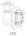
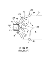
- Figs. 9 to 11 represents an examples of a typical well-known gas turbine combustor of a conventional structure.
- a plurality of gas turbine combustors are arranged on the outer peripheral portion of a discharge casing 2 of an air conditioner 1.
- a combustor liner 5 by which an internal combustion chamber 4 is enclosed is housed within the combustor casing 3, and a nozzle head 6, an igniter 7 and a flame detector, not shown, are provided in the internal combustion chamber 4.
- the nozzle head 6 is mounted on a head plate 8, and this head plate 8 and a flow sleeve 9 are mounted on the combustor casing 3.
- the head plate 8 is disposed so as to close one end of the casing 3.
- a fuel jetting nozzle 10 is mounted on the nozzle head 6 and prevented from rotating by a locking plate 11.
- the combustor liner 5 is mounted on the extreme, i.e. front, end portion of the fuel jetting nozzle 10, and a liner supporter 12 provided on the flow sleeve 9 supports the combustor liner 5.
- a transition piece 13 is connected to the extreme end portion (the downstream area) of the combustor liner 5.
- the combustor liner 5 is connected to a first-stage turbine stationary blade 14a of a gas turbine 14 by way of the transition piece 13.
- An air intake passage 15 is formed in the outer peripheral portion of the fuel jetting nozzle 10.
- a swirl vane 16 is disposed between the air intake passage 15 and the internal combustion chamber 4.
- Fuel jetting holes 17, through which the inside of the fuel jetting nozzle 10 is communicated with the swirl vane 16, are provided on the peripheral wall portion of the fuel jetting nozzle 10.
- the front side of a central end portion 18 of the fuel jetting nozzle 10 faces the inside of the internal combustion chamber 4 and forms a portion thereof.
- a fuel intake 19 is formed in the nozzle head 6, from which a gaseous fuel 20 is introduced into the fuel jetting nozzle 10.
- An air flow around the gas turbine combustor will be explained hereunder.
- An air 21 discharged from the air conditioner 1 flows around the transition piece 13 and is guided in a direction opposite to the flow of combustion gas 22 between the combustor liner 5 and the flow sleeve 9.
- the discharged air 21 is introduced into the internal combustion chamber 4 through air passages which are broadly divided into three portions. That is, the discharged air 21 is divided into primary air 23 introduced from the swirl vane 16 around the fuel jetting nozzle 10, secondary air 25 introduced from an air guide 24 provided on the trunk portion of the combustor liner 5, and tertiary air 26 for dilution purposes introduced from the holes provided downstream of the air guide 24 used for the secondary air.
- a stable annular vortex area, i.e. flame area, of the primary air 23 and the gaseous fuel 20 is formed in the inside of the annular swirl flow caused by the primary air 23.
- the stable annular vortex area stabilizes and maintains the combustion flame, and the combustion gas 22 flows to the exit area of the combustor liner 5.
- the primary air 23 is mixed with the tertiary air 26, and cools the combustor liner 5 and decreases the gas temperature so that the liner exit temperature becomes a temperature required for the turbine.
- the primary air 23, the secondary air 25 and the tertiary air 26 are allocated in various ways so as to control combustion performance. In some instances, the secondary air 25 and tertiary air 26 may not be provided. Furthermore, the primary air 23 and the secondary air 25 may be mixed with the gaseous fuel 20 beforehand and introduced into the internal combustion chamber 4.
- the discharged air 21 passes through a slot, not shown, used to cool the combustor liner 5 and is supplied to the internal combustion chamber 4.
- the combustion gas 22 passes the transition piece 13 and is introduced to the first-stage turbine stationary blade 14a of the gas turbine 14, causing a turbine rotor, not shown, to rotate by using the energy thereof.
- the primary air 23 passes the swirl vanes 16 of the fuel jetting nozzle 10 and flows into the internal combustion chamber 4 while it is being swirled.
- the secondary air 25 which flows into the internal combustion chamber 4 through the air guide 24 provided in the trunk portion of the combustor liner 5 flows into a swirling flow 27 formed by air passing through the fuel jetting nozzle 10, forming a reverse flow, i.e. vortex flow, flame area 28 in the central portion and a reverse flow, i.e. vortex flow, flame area 29 in the outer periphery.
- the local temperature of the combustion gas inside the reverse flow flame area 28 in the central portion becomes a high temperature above approximately 2,000 °C and a stable flame can thus be maintained.
- An object of the present invention is to substantially eliminate defect or drawbacks encountered in the prior art descibed above and to provide a fuel jetting nozzle assembly for use in a gas turbine combustor in which service life of the fuel jetting nozzle is lengthened by preventing a burn damage to the central end portion of the jetting nozzle by a location of a cooling means.
- a fuel jetting nozzle assembly for use in a gas turbine combustor comprising an outer casing, a combustor liner disposed inside the outer casing and having a combustion chamber, a head plate closing one end of the outer casing and a fuel jetting nozzle assembly, the fuel jetting nozzle assembly comprising:
- the swirling means comprises a plurality of swirling vanes disposed on the outer peripheral portion of the fuel jetting nozzle means and separated equally.
- the fuel jetting holes are formed at base portions of the swirling vanes, respectively, and each of the cooling holes are positioned between adjacent two fuel jetting holes.
- Each of the cooling holes has an inward inclination with respect to a front surface of the central portion of the front end portion of the fuel jetting nozzle means, the inward inclination of the cooling hole having a swirling angle component having a same direction as that of a swirling angle of the swirling vane.
- the cooling means further comprises an air introducing pipe disposed to the front end portion of the fuel jetting nozzle means and an air header attached to an inner surface of the front end portion of the fuel jetting nozzle means, the air introducing pipe having one end communicated with the air header and another end opened to a discharge air side.
- a fuel jetting nozzle assembly for use in a gas turbine combustor comprising an outer casing, a combustor liner disposed inside the outer casing and having a combustion chamber, a head plate closing one end of the outer casing and a fuel jetting nozzle assembly, the fuel jetting nozzle assembly comprising:
- the cooling means comprises a pipe having one end communicated with the nozzle head and another end opened in the fuel jetting nozzle means. Another end of the pipe is formed with a plurality of fuel jetting holes.
- a coating is applied to the front surface of the central portion of the front end portion of the fuel jetting nozzle means with a substance having a coefficient of thermal conductivity lower than that of a substance constituting the fuel jetting nozzle means.
- the central end portion of the fuel jetting nozzle is cooled by the forced convection of air which passes through cooling holes and the air is introduced to the front side thereof.
- the central end portion of the fuel jetting nozzle can be cooled by an air layer formed by that air in the central end portion of the fuel jetting nozzle. As a result, a burn damage to the fuel jetting nozzle can be prevented.
- the high-temperature portion of the central end portion of the fuel jetting nozzle can be cooled by the forced convection using colliding jets caused by a gaseous fuel which is introduced by the cooling means. As a result, the burn damage to the fuel jetting nozzle can be prevented.
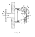
- Figs. 1 to 4 illustrate a first embodiment of a fuel jetting nozzle assembly for use in a gas turbine combustor according to the present invention.
- Components which are the same as those in a conventional fuel jetting nozzle assembly shown in Figs. 9 to 11 are given the same reference numerals, and thus an explanation thereof is omitted herein.
- a basic difference of the fuel jetting nozzle of the present invention from the conventional one is that a plurality of swirl vanes 16 by which fuel air is made to flow into the internal combustion chamber 4 are evenly arranged circumferentially on the outer peripheral portion of the fuel jetting nozzle 10, and that fuel jetting holes 17 are provided on the base portions of the swirl vanes 16.
- the fuel jetting nozzle 10 is fastened to the nozzle head 6 having the fuel intake 19.
- Each of cooling holes 30, formed at the base portions of the respective swirl vanes 16 and positioned between the adjacnet two fuel jetting holes 17, which reaches the front of the central portion 18 of the front end portion of the fuel jetting nozzle 10 from an area upstream of the swirl vanes 16, is provided on the peripheral wall of the fuel jetting nozzle 10.
- Each of the cooling holes 30 is provided with an inward angle-y with respect to the front side of the central end portion 18 of the fuel jetting nozzle 10. As shown in Fig.3, it has a swirl angle component in the same direction as that of the swirl angle a of the swirl vanes 16.
- cooling air 31 flows out to the front side of the central flame area 28 while it takes away heat by forced convection cooling, which heat flows in from the front side of the fuel jetting nozzle 10.
- the air flown out to the front side of the central flame area 28 forms an air layer in front of the central end portion 18 of the fuel jetting nozzle 10.
- the front side is protected from fuel gas by film-cooling effect.
- the cooling hole 30 is provided with a swirl angle component in the same direction as the swirl angle of the swirl vane 16 and also with an inward angle -y , the cooling air 31 is expanded on the front side of the central end portion 18 of the fuel jetting nozzle 10 while it is being swirled. As a result, a high film-cooling effect can be attained.
- the central end portion 18 of the fuel jetting nozzle 10 can be cooled by the forced convection using the cooling air 31 passing through the cooling holes 30 and by the film-cooling effect using an air layer. As a result, a burn damage to the central end portion 18 of the fuel jetting nozzle 10 can be prevented.
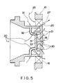
- Fig. 5 illustrates a second embodiment of a fuel jetting nozzle for use in a gas turbine combustor according to the present invention.
- a point of difference of this embodiment from the fuel jetting nozzle explained in the first embodiment is that a pipe 32 and an air header 33 are provided, and that when once some of the discharged air 21 is introduced by the pipe 32 as the cooling air 31 into the air header 33, the air is made to flow out from the inside of the header to the front side of the central end portion 18 of the fuel jetting nozzle 10 through a plurality of cooling holes 30.
- the air introducing pipe 32 is mounted to the front end portion of the fuel jetting nozzle and the air header 33 is attached to an inner surface of the front end portion of the fuel jetting nozzle, the air introducing pipe 32 having one end communicated with the air header 33 and another end opened to a discharge air side.
- the cooling holes 30 can be compactly arranged as desired, a minimum amount of cooling air required can be allocated on the basis of the distribution of the amount of heat which enters from the gaseous fuel 20 into the fuel jetting nozzle 10.
- the front side of the central end portion 18 of the fuel jetting nozzle 10 can be cooled more uniformly.
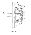
- Fig. 6 illustrates a third embodiment of a fuel jetting nozzle for use in a gas turbine combustor according to the present invention.
- a plurality of swirl vanes 16 by which fuel air is made to flow in are evenly arranged circumferentially on the outer peripheral portion of the fuel jetting nozzle 10, and fuel jetting holes 17 are provided on the base portions of the swirl vanes 16. This is fastened to the nozzle head 6 having the fuel intake 19.
- a pipe 34, serving as cooling means, for introducing the gaseous fuel 20 to the inner side of the central end portion 18 of the fuel jetting nozzle 10 is disposed in the central portion.
- the pipe 34 has one end communicated with the nozzle head and another end opened in the fuel jetting nozzle 10.
- the gaseous fuel 20 flows in from the fuel intake 19, passes through the pipe 34, flows out into the fuel jetting nozzle 10 in the form of jets, and collides with the inner side of the central end portion 18, thereby cooling this portion by the forced convection. Thereafter, the gaseous fuel 20 is jetted from the fuel jetting holes 17, mixed with the primary air 23, passes the swirl vanes 16 provided in the periphery of the fuel jetting nozzle 10, and flows out as an annular swirl flow into the internal combustion chamber 4, forming the central reverse flow flame area 28.
- the front side of the central end portion 18 of the fuel jetting nozzle 10 may be coated (thermal barrier coating) with a material 35, such as zirconium oxide, having thermal conductivity lower than that of component metals of the fuel jetting nozzle 10 in order to reduce thermal stress caused by a temperature difference with the inside of the combustion chamber 4.
- a material 35 such as zirconium oxide
- a porous plate 36 may be provided in the extreme end portion of the pipe 34 serving as cooling means to make it possible to cool the inner side of the central end portion 18 of the fuel jetting nozzle 10 by a plurality of colliding jets.
Landscapes
- Engineering & Computer Science (AREA)
- Chemical & Material Sciences (AREA)
- Combustion & Propulsion (AREA)
- Mechanical Engineering (AREA)
- General Engineering & Computer Science (AREA)
- Turbine Rotor Nozzle Sealing (AREA)
- Nozzles For Spraying Of Liquid Fuel (AREA)
Priority Applications (1)
| Application Number | Priority Date | Filing Date | Title |
|---|---|---|---|
| EP96113426A EP0751345B1 (de) | 1991-12-24 | 1992-12-22 | Kraftstoff-Einspritzdüsen-Anordnung zur Verwendung in einer Gasturbinen-Brennkammer |
Applications Claiming Priority (2)
| Application Number | Priority Date | Filing Date | Title |
|---|---|---|---|
| JP341206/91 | 1991-12-24 | ||
| JP3341206A JP2839777B2 (ja) | 1991-12-24 | 1991-12-24 | ガスタービン燃焼器用燃料噴射ノズル |
Related Child Applications (1)
| Application Number | Title | Priority Date | Filing Date |
|---|---|---|---|
| EP96113426.9 Division-Into | 1996-08-21 |
Publications (3)
| Publication Number | Publication Date |
|---|---|
| EP0548908A2 true EP0548908A2 (de) | 1993-06-30 |
| EP0548908A3 EP0548908A3 (en) | 1993-08-25 |
| EP0548908B1 EP0548908B1 (de) | 1997-10-22 |
Family
ID=18344201
Family Applications (2)
| Application Number | Title | Priority Date | Filing Date |
|---|---|---|---|
| EP92121790A Expired - Lifetime EP0548908B1 (de) | 1991-12-24 | 1992-12-22 | Kraftstoff-Einspritzdüsen-Anordnung zur Verwendung in einer Gasturbinen-Brennkammer |
| EP96113426A Expired - Lifetime EP0751345B1 (de) | 1991-12-24 | 1992-12-22 | Kraftstoff-Einspritzdüsen-Anordnung zur Verwendung in einer Gasturbinen-Brennkammer |
Family Applications After (1)
| Application Number | Title | Priority Date | Filing Date |
|---|---|---|---|
| EP96113426A Expired - Lifetime EP0751345B1 (de) | 1991-12-24 | 1992-12-22 | Kraftstoff-Einspritzdüsen-Anordnung zur Verwendung in einer Gasturbinen-Brennkammer |
Country Status (4)
| Country | Link |
|---|---|
| US (1) | US5351489A (de) |
| EP (2) | EP0548908B1 (de) |
| JP (1) | JP2839777B2 (de) |
| CA (1) | CA2086140C (de) |
Cited By (10)
| Publication number | Priority date | Publication date | Assignee | Title |
|---|---|---|---|---|
| WO1995005561A1 (en) * | 1993-08-16 | 1995-02-23 | Solar Turbines Incorporated | Injector tip cooling using fuel as the coolant |
| WO1995022033A1 (en) * | 1994-02-10 | 1995-08-17 | Solar Turbines Incorporated | Injector having low tip temperature |
| EP0945677A3 (de) * | 1998-03-24 | 2000-01-19 | United Technologies Corporation | Brennstoffeinspritzvorrichtung mit Flammenstabilisierung |
| EP0851105A3 (de) * | 1996-12-23 | 2000-04-12 | General Electric Company | Brennstoffzerstäubung in einer Gasturbine mittels vorgekühlter Kühlluft |
| EP1184621A1 (de) * | 2000-08-31 | 2002-03-06 | General Electric Company | Düse für Gasbrenner und Verfahren zum Kühlen derselben |
| CN102538007A (zh) * | 2010-12-06 | 2012-07-04 | 通用电气公司 | 空气分级扩散喷嘴 |
| CN101387410B (zh) * | 2007-08-21 | 2012-10-10 | 通用电气公司 | 燃料喷嘴和用于燃料喷嘴的扩散尖端 |
| US8925323B2 (en) | 2012-04-30 | 2015-01-06 | General Electric Company | Fuel/air premixing system for turbine engine |
| EP2853818A1 (de) * | 2013-09-26 | 2015-04-01 | Siemens Aktiengesellschaft | Brenner für ein Verbrennungssystem mit Vormischelement und Kühlelement, Verbrennungssystem mit Brenner und Verwendung des Verbrennungssystems |
| CN109611889A (zh) * | 2018-12-07 | 2019-04-12 | 中国航发沈阳发动机研究所 | 一种气体燃料喷嘴组件 |
Families Citing this family (30)
| Publication number | Priority date | Publication date | Assignee | Title |
|---|---|---|---|---|
| US6067790A (en) * | 1996-01-05 | 2000-05-30 | Choi; Kyung J. | Lean direct wall fuel injection method and devices |
| JP3327772B2 (ja) * | 1996-05-24 | 2002-09-24 | 三菱重工業株式会社 | 燃焼器の火炎検知器の掃除方法及び装置 |
| EP0918190A1 (de) * | 1997-11-21 | 1999-05-26 | Abb Research Ltd. | Brenner für den Betrieb eines Wärmeerzeugers |
| US6082113A (en) * | 1998-05-22 | 2000-07-04 | Pratt & Whitney Canada Corp. | Gas turbine fuel injector |
| US6289676B1 (en) | 1998-06-26 | 2001-09-18 | Pratt & Whitney Canada Corp. | Simplex and duplex injector having primary and secondary annular lud channels and primary and secondary lud nozzles |
| EP1255613A1 (de) | 2000-02-03 | 2002-11-13 | Corning Incorporated | Feuerfeste brennerdüse mit entspannungsschlitzen |
| US6763663B2 (en) * | 2001-07-11 | 2004-07-20 | Parker-Hannifin Corporation | Injector with active cooling |
| US6813889B2 (en) | 2001-08-29 | 2004-11-09 | Hitachi, Ltd. | Gas turbine combustor and operating method thereof |
| US6928823B2 (en) | 2001-08-29 | 2005-08-16 | Hitachi, Ltd. | Gas turbine combustor and operating method thereof |
| DE10219354A1 (de) | 2002-04-30 | 2003-11-13 | Rolls Royce Deutschland | Gasturbinenbrennkammer mit gezielter Kraftstoffeinbringung zur Verbesserung der Homogenität des Kraftstoff-Luft-Gemisches |
| US6886342B2 (en) * | 2002-12-17 | 2005-05-03 | Pratt & Whitney Canada Corp. | Vortex fuel nozzle to reduce noise levels and improve mixing |
| US8397510B2 (en) | 2003-12-16 | 2013-03-19 | Hitachi, Ltd. | Combustor for gas turbine |
| DE102007043626A1 (de) | 2007-09-13 | 2009-03-19 | Rolls-Royce Deutschland Ltd & Co Kg | Gasturbinenmagerbrenner mit Kraftstoffdüse mit kontrollierter Kraftstoffinhomogenität |
| US7578369B2 (en) * | 2007-09-25 | 2009-08-25 | Hamilton Sundstrand Corporation | Mixed-flow exhaust silencer assembly |
| KR101049359B1 (ko) * | 2008-10-31 | 2011-07-13 | 한국전력공사 | 삼중 스월형 가스터빈 연소기 |
| US8479519B2 (en) * | 2009-01-07 | 2013-07-09 | General Electric Company | Method and apparatus to facilitate cooling of a diffusion tip within a gas turbine engine |
| FR2941288B1 (fr) * | 2009-01-16 | 2011-02-18 | Snecma | Dispositif d'injection d'un melange d'air et de carburant dans une chambre de combustion de turbomachine |
| US20100281872A1 (en) * | 2009-05-06 | 2010-11-11 | Mark Allan Hadley | Airblown Syngas Fuel Nozzle With Diluent Openings |
| US8607570B2 (en) * | 2009-05-06 | 2013-12-17 | General Electric Company | Airblown syngas fuel nozzle with diluent openings |
| US8141363B2 (en) * | 2009-10-08 | 2012-03-27 | General Electric Company | Apparatus and method for cooling nozzles |
| US8991188B2 (en) | 2011-01-05 | 2015-03-31 | General Electric Company | Fuel nozzle passive purge cap flow |
| JP5631223B2 (ja) * | 2011-01-14 | 2014-11-26 | 三菱重工業株式会社 | 燃料ノズル、これを備えたガスタービン燃焼器およびこれを備えたガスタービン |
| RU2560099C2 (ru) * | 2011-01-31 | 2015-08-20 | Дженерал Электрик Компани | Топливное сопло (варианты) |
| US8556027B2 (en) | 2011-06-28 | 2013-10-15 | United Technologies Corporation | Eductor exhaust silencer assembly with bypass gasflow |
| US20130263605A1 (en) * | 2012-04-04 | 2013-10-10 | General Electric | Diffusion Combustor Fuel Nozzle |
| EP3318804B1 (de) * | 2015-07-03 | 2021-01-20 | Mitsubishi Power, Ltd. | Brennkammerdüse, gasturbinenbrennkammer, gasturbine, abdeckring und verfahren zur herstellung einer brennkammerdüse |
| CN108613177B (zh) * | 2018-05-24 | 2023-11-28 | 国家能源集团谏壁发电厂 | 一种带有喷头冷却装置的油燃烧器 |
| CN111288448B (zh) * | 2020-03-20 | 2022-03-29 | 东营富润智能科技有限公司 | 一种油田加热炉用超低氮燃烧器 |
| US12011734B2 (en) * | 2020-09-15 | 2024-06-18 | Rtx Corporation | Fuel nozzle air swirler |
| CN119042666B (zh) * | 2024-07-02 | 2025-11-21 | 北京航空航天大学 | 一种采用多孔阵列排布的氢燃料微扩散分级燃烧室 |
Family Cites Families (15)
| Publication number | Priority date | Publication date | Assignee | Title |
|---|---|---|---|---|
| FR1316988A (fr) * | 1962-03-07 | 1963-02-01 | Babcock & Wilcox France | Perfectionnements aux appareils de combustion |
| US3630024A (en) * | 1970-02-02 | 1971-12-28 | Gen Electric | Air swirler for gas turbine combustor |
| US3570242A (en) * | 1970-04-20 | 1971-03-16 | United Aircraft Corp | Fuel premixing for smokeless jet engine main burner |
| GB1377184A (en) * | 1971-02-02 | 1974-12-11 | Secr Defence | Gas turbine engine combustion apparatus |
| US3777983A (en) * | 1971-12-16 | 1973-12-11 | Gen Electric | Gas cooled dual fuel air atomized fuel nozzle |
| US4198815A (en) * | 1975-12-24 | 1980-04-22 | General Electric Company | Central injection fuel carburetor |
| JPS5279111A (en) * | 1975-12-25 | 1977-07-04 | Hitachi Ltd | Combustor |
| FR2484020A1 (fr) * | 1980-06-06 | 1981-12-11 | Snecma | Ensemble d'injection de carburant pour chambre de turboreacteur |
| RO77519A2 (ro) * | 1980-12-27 | 1983-09-26 | Institutul National De Motoare Termice,Ro | Injector de combustibili lichizi |
| GB2101732A (en) * | 1981-05-12 | 1983-01-19 | Rolls Royce | Gas turbine engine fuel injector |
| GB2175993B (en) * | 1985-06-07 | 1988-12-21 | Rolls Royce | Improvements in or relating to dual fuel injectors |
| JPS6281864A (ja) * | 1985-10-04 | 1987-04-15 | Nec Corp | 中継台転送方式 |
| JPH0667590B2 (ja) * | 1986-10-22 | 1994-08-31 | 積水化成品工業株式会社 | 複合容器の成形装置 |
| US4825658A (en) * | 1987-12-11 | 1989-05-02 | General Electric Company | Fuel nozzle with catalytic glow plug |
| GB2215029B (en) * | 1988-02-06 | 1991-10-09 | Rolls Royce Plc | Gas turbine engine fuel burner |
-
1991
- 1991-12-24 JP JP3341206A patent/JP2839777B2/ja not_active Expired - Fee Related
-
1992
- 1992-12-22 EP EP92121790A patent/EP0548908B1/de not_active Expired - Lifetime
- 1992-12-22 EP EP96113426A patent/EP0751345B1/de not_active Expired - Lifetime
- 1992-12-23 US US07/996,165 patent/US5351489A/en not_active Expired - Lifetime
- 1992-12-23 CA CA002086140A patent/CA2086140C/en not_active Expired - Lifetime
Cited By (12)
| Publication number | Priority date | Publication date | Assignee | Title |
|---|---|---|---|---|
| WO1995005561A1 (en) * | 1993-08-16 | 1995-02-23 | Solar Turbines Incorporated | Injector tip cooling using fuel as the coolant |
| WO1995022033A1 (en) * | 1994-02-10 | 1995-08-17 | Solar Turbines Incorporated | Injector having low tip temperature |
| EP0851105A3 (de) * | 1996-12-23 | 2000-04-12 | General Electric Company | Brennstoffzerstäubung in einer Gasturbine mittels vorgekühlter Kühlluft |
| EP0945677A3 (de) * | 1998-03-24 | 2000-01-19 | United Technologies Corporation | Brennstoffeinspritzvorrichtung mit Flammenstabilisierung |
| EP1184621A1 (de) * | 2000-08-31 | 2002-03-06 | General Electric Company | Düse für Gasbrenner und Verfahren zum Kühlen derselben |
| CZ299515B6 (cs) * | 2000-08-31 | 2008-08-20 | General Electric Company | Tryska pro provoz pouze na plyn a zpusob chlazenípalivové špicky |
| CN101387410B (zh) * | 2007-08-21 | 2012-10-10 | 通用电气公司 | 燃料喷嘴和用于燃料喷嘴的扩散尖端 |
| CN102538007A (zh) * | 2010-12-06 | 2012-07-04 | 通用电气公司 | 空气分级扩散喷嘴 |
| US8925323B2 (en) | 2012-04-30 | 2015-01-06 | General Electric Company | Fuel/air premixing system for turbine engine |
| EP2853818A1 (de) * | 2013-09-26 | 2015-04-01 | Siemens Aktiengesellschaft | Brenner für ein Verbrennungssystem mit Vormischelement und Kühlelement, Verbrennungssystem mit Brenner und Verwendung des Verbrennungssystems |
| WO2015043786A1 (en) * | 2013-09-26 | 2015-04-02 | Siemens Aktiengesellschaft | Burner for a combustion system with a premixing element and cooling element, combustion system with the burner and use of the combustion system |
| CN109611889A (zh) * | 2018-12-07 | 2019-04-12 | 中国航发沈阳发动机研究所 | 一种气体燃料喷嘴组件 |
Also Published As
| Publication number | Publication date |
|---|---|
| CA2086140C (en) | 1996-04-02 |
| JP2839777B2 (ja) | 1998-12-16 |
| EP0548908A3 (en) | 1993-08-25 |
| CA2086140A1 (en) | 1993-06-25 |
| EP0548908B1 (de) | 1997-10-22 |
| EP0751345B1 (de) | 2000-04-19 |
| US5351489A (en) | 1994-10-04 |
| JPH05172331A (ja) | 1993-07-09 |
| EP0751345A1 (de) | 1997-01-02 |
Similar Documents
| Publication | Publication Date | Title |
|---|---|---|
| US5351489A (en) | Fuel jetting nozzle assembly for use in gas turbine combustor | |
| US6427446B1 (en) | Low NOx emission combustion liner with circumferentially angled film cooling holes | |
| EP1253380B1 (de) | Verfahren und Vorrichtung zur Kühlung von Gasturbinenbrennkammern | |
| EP1253379B1 (de) | Verfahren und Vorrichtung zur Kühlung von Gasturbinenbrennkammern | |
| KR100239082B1 (ko) | 가스터어빈 연소기 및 이중방식 연소기에 사용하는 중심체 구조물 | |
| US5127221A (en) | Transpiration cooled throat section for low nox combustor and related process | |
| US7080515B2 (en) | Gas turbine can annular combustor | |
| CA2399534C (en) | Gasturbine and the combustor thereof | |
| CA2546881C (en) | Gas turbine engine combustor with improved cooling | |
| CA2583400C (en) | Gas turbine engine combustor with improved cooling | |
| US2916878A (en) | Air-directing vane structure for fluid fuel combustor | |
| EP1258681B1 (de) | Verfahren und Vorrichtung zur Kühlung einer Gasturbinenverbrennungskammer | |
| US5117624A (en) | Fuel injector nozzle support | |
| US4852355A (en) | Dispensing arrangement for pressurized air | |
| EP1271059A2 (de) | Verfahren und Systeme zur Kühlung von Gasturbinenbrennkammern | |
| JP2008510955A (ja) | 熱保護体のない燃焼器および燃焼器ライナの冷却 | |
| EP3086043B1 (de) | Vormischpilotdüse | |
| US8307660B2 (en) | Combustor nozzle and method for supplying fuel to a combustor | |
| US20150047364A1 (en) | Burner arrangement and method for operating a burner arrangement | |
| BRPI1101657A2 (pt) | sistema de resfriamento de vedação em ángulo | |
| US4944152A (en) | Augmented turbine combustor cooling | |
| CN102356279B (zh) | 尤其用于燃气轮机的燃烧器的工作方法和燃烧器 | |
| JPH0882419A (ja) | ガスタービン用燃焼器 | |
| JP2002155758A (ja) | 冷却構造及びそれを用いた燃焼器 | |
| JPH03195821A (ja) | ガスタービン燃焼器 |
Legal Events
| Date | Code | Title | Description |
|---|---|---|---|
| PUAI | Public reference made under article 153(3) epc to a published international application that has entered the european phase |
Free format text: ORIGINAL CODE: 0009012 |
|
| 17P | Request for examination filed |
Effective date: 19921226 |
|
| AK | Designated contracting states |
Kind code of ref document: A2 Designated state(s): FR GB |
|
| PUAL | Search report despatched |
Free format text: ORIGINAL CODE: 0009013 |
|
| AK | Designated contracting states |
Kind code of ref document: A3 Designated state(s): FR GB |
|
| 17Q | First examination report despatched |
Effective date: 19950411 |
|
| GRAG | Despatch of communication of intention to grant |
Free format text: ORIGINAL CODE: EPIDOS AGRA |
|
| GRAH | Despatch of communication of intention to grant a patent |
Free format text: ORIGINAL CODE: EPIDOS IGRA |
|
| GRAH | Despatch of communication of intention to grant a patent |
Free format text: ORIGINAL CODE: EPIDOS IGRA |
|
| GRAA | (expected) grant |
Free format text: ORIGINAL CODE: 0009210 |
|
| AK | Designated contracting states |
Kind code of ref document: B1 Designated state(s): FR GB |
|
| DX | Miscellaneous (deleted) | ||
| ET | Fr: translation filed | ||
| PLBE | No opposition filed within time limit |
Free format text: ORIGINAL CODE: 0009261 |
|
| STAA | Information on the status of an ep patent application or granted ep patent |
Free format text: STATUS: NO OPPOSITION FILED WITHIN TIME LIMIT |
|
| 26N | No opposition filed | ||
| REG | Reference to a national code |
Ref country code: GB Ref legal event code: IF02 |
|
| REG | Reference to a national code |
Ref country code: GB Ref legal event code: 746 Effective date: 20070318 |
|
| PGFP | Annual fee paid to national office [announced via postgrant information from national office to epo] |
Ref country code: GB Payment date: 20101222 Year of fee payment: 19 |
|
| PGFP | Annual fee paid to national office [announced via postgrant information from national office to epo] |
Ref country code: FR Payment date: 20111219 Year of fee payment: 20 |
|
| REG | Reference to a national code |
Ref country code: GB Ref legal event code: PE20 Expiry date: 20121221 |
|
| PG25 | Lapsed in a contracting state [announced via postgrant information from national office to epo] |
Ref country code: GB Free format text: LAPSE BECAUSE OF EXPIRATION OF PROTECTION Effective date: 20121221 |