EP0549285A2 - Appareil pour mesurer le déplacement par variation en fréquence d'un oscillateur - Google Patents
Appareil pour mesurer le déplacement par variation en fréquence d'un oscillateur Download PDFInfo
- Publication number
- EP0549285A2 EP0549285A2 EP92311610A EP92311610A EP0549285A2 EP 0549285 A2 EP0549285 A2 EP 0549285A2 EP 92311610 A EP92311610 A EP 92311610A EP 92311610 A EP92311610 A EP 92311610A EP 0549285 A2 EP0549285 A2 EP 0549285A2
- Authority
- EP
- European Patent Office
- Prior art keywords
- oscillator
- displacement
- frequency
- measuring
- sensor head
- Prior art date
- Legal status (The legal status is an assumption and is not a legal conclusion. Google has not performed a legal analysis and makes no representation as to the accuracy of the status listed.)
- Granted
Links
- 238000006073 displacement reaction Methods 0.000 title claims abstract description 33
- 230000008859 change Effects 0.000 claims abstract description 16
- 230000004044 response Effects 0.000 claims description 4
- 239000013078 crystal Substances 0.000 abstract description 2
- 238000000034 method Methods 0.000 description 4
- 230000010355 oscillation Effects 0.000 description 4
- 230000008569 process Effects 0.000 description 3
- 230000008901 benefit Effects 0.000 description 2
- 238000010586 diagram Methods 0.000 description 2
- 239000000696 magnetic material Substances 0.000 description 2
- 238000005259 measurement Methods 0.000 description 2
- 239000002184 metal Substances 0.000 description 2
- 229910045601 alloy Inorganic materials 0.000 description 1
- 239000000956 alloy Substances 0.000 description 1
- 230000003321 amplification Effects 0.000 description 1
- 238000006243 chemical reaction Methods 0.000 description 1
- 230000000295 complement effect Effects 0.000 description 1
- 239000003302 ferromagnetic material Substances 0.000 description 1
- 230000006870 function Effects 0.000 description 1
- 238000009434 installation Methods 0.000 description 1
- 238000005305 interferometry Methods 0.000 description 1
- 238000003199 nucleic acid amplification method Methods 0.000 description 1
- 229920003023 plastic Polymers 0.000 description 1
- 239000004033 plastic Substances 0.000 description 1
- 229910000859 α-Fe Inorganic materials 0.000 description 1
Images

Classifications
-
- G—PHYSICS
- G01—MEASURING; TESTING
- G01B—MEASURING LENGTH, THICKNESS OR SIMILAR LINEAR DIMENSIONS; MEASURING ANGLES; MEASURING AREAS; MEASURING IRREGULARITIES OF SURFACES OR CONTOURS
- G01B7/00—Measuring arrangements characterised by the use of electric or magnetic techniques
- G01B7/16—Measuring arrangements characterised by the use of electric or magnetic techniques for measuring the deformation in a solid, e.g. by resistance strain gauge
-
- G—PHYSICS
- G01—MEASURING; TESTING
- G01D—MEASURING NOT SPECIALLY ADAPTED FOR A SPECIFIC VARIABLE; ARRANGEMENTS FOR MEASURING TWO OR MORE VARIABLES NOT COVERED IN A SINGLE OTHER SUBCLASS; TARIFF METERING APPARATUS; MEASURING OR TESTING NOT OTHERWISE PROVIDED FOR
- G01D5/00—Mechanical means for transferring the output of a sensing member; Means for converting the output of a sensing member to another variable where the form or nature of the sensing member does not constrain the means for converting; Transducers not specially adapted for a specific variable
- G01D5/12—Mechanical means for transferring the output of a sensing member; Means for converting the output of a sensing member to another variable where the form or nature of the sensing member does not constrain the means for converting; Transducers not specially adapted for a specific variable using electric or magnetic means
- G01D5/14—Mechanical means for transferring the output of a sensing member; Means for converting the output of a sensing member to another variable where the form or nature of the sensing member does not constrain the means for converting; Transducers not specially adapted for a specific variable using electric or magnetic means influencing the magnitude of a current or voltage
- G01D5/20—Mechanical means for transferring the output of a sensing member; Means for converting the output of a sensing member to another variable where the form or nature of the sensing member does not constrain the means for converting; Transducers not specially adapted for a specific variable using electric or magnetic means influencing the magnitude of a current or voltage by varying inductance, e.g. by a movable armature
- G01D5/22—Mechanical means for transferring the output of a sensing member; Means for converting the output of a sensing member to another variable where the form or nature of the sensing member does not constrain the means for converting; Transducers not specially adapted for a specific variable using electric or magnetic means influencing the magnitude of a current or voltage by varying inductance, e.g. by a movable armature differentially influencing two coils
- G01D5/2208—Mechanical means for transferring the output of a sensing member; Means for converting the output of a sensing member to another variable where the form or nature of the sensing member does not constrain the means for converting; Transducers not specially adapted for a specific variable using electric or magnetic means influencing the magnitude of a current or voltage by varying inductance, e.g. by a movable armature differentially influencing two coils by influencing the self-induction of the coils
- G01D5/2216—Mechanical means for transferring the output of a sensing member; Means for converting the output of a sensing member to another variable where the form or nature of the sensing member does not constrain the means for converting; Transducers not specially adapted for a specific variable using electric or magnetic means influencing the magnitude of a current or voltage by varying inductance, e.g. by a movable armature differentially influencing two coils by influencing the self-induction of the coils by a movable ferromagnetic element, e.g. a core
-
- G—PHYSICS
- G01—MEASURING; TESTING
- G01B—MEASURING LENGTH, THICKNESS OR SIMILAR LINEAR DIMENSIONS; MEASURING ANGLES; MEASURING AREAS; MEASURING IRREGULARITIES OF SURFACES OR CONTOURS
- G01B7/00—Measuring arrangements characterised by the use of electric or magnetic techniques
- G01B7/02—Measuring arrangements characterised by the use of electric or magnetic techniques for measuring length, width or thickness
-
- G—PHYSICS
- G01—MEASURING; TESTING
- G01D—MEASURING NOT SPECIALLY ADAPTED FOR A SPECIFIC VARIABLE; ARRANGEMENTS FOR MEASURING TWO OR MORE VARIABLES NOT COVERED IN A SINGLE OTHER SUBCLASS; TARIFF METERING APPARATUS; MEASURING OR TESTING NOT OTHERWISE PROVIDED FOR
- G01D3/00—Indicating or recording apparatus with provision for the special purposes referred to in the subgroups
- G01D3/02—Indicating or recording apparatus with provision for the special purposes referred to in the subgroups with provision for altering or correcting the law of variation
- G01D3/022—Indicating or recording apparatus with provision for the special purposes referred to in the subgroups with provision for altering or correcting the law of variation having an ideal characteristic, map or correction data stored in a digital memory
-
- G—PHYSICS
- G01—MEASURING; TESTING
- G01B—MEASURING LENGTH, THICKNESS OR SIMILAR LINEAR DIMENSIONS; MEASURING ANGLES; MEASURING AREAS; MEASURING IRREGULARITIES OF SURFACES OR CONTOURS
- G01B2210/00—Aspects not specifically covered by any group under G01B, e.g. of wheel alignment, caliper-like sensors
- G01B2210/60—Unique sensor identification
Definitions
- This invention relates to apparatus for measuring displacement using a sensor in association with processing means for calibration, linearisation and digital conversion.
- apparatus for measuring displacement comprising a sensor head for varying the frequency of an oscillator in response to the displacement to be measured, means for measuring the frequency change, and a micro-processor for converting the measured frequency change to a digital output representing the displacement by reference to stored calibration coefficients specific to the sensor head, wherein the frequency measuring means, and micro-processor are mounted in a connector for connection to similar connectors of other sensor heads, and the microprocessor contains a unique I.D. for that sensor head, allowing a host computer to identify each sensor head.
- the calibration coefficients form a look-up table which is conveniently stored in a ROM.
- a displacement sensor embodying the invention may have a number of advantages, most notably, by converting the mechanical displacement into a shift in frequency, the sensor is able to produce a digital output without the need for high gain amplifiers or a/d converters. Also, the electronics to operate the sensor, are mounted in a connector providing a compact unit which requires no further processing electronics and which can be directly coupled to a number of other similar sensors.
- apparatus for measuring displacement comprising a sensor head for varying the frequency of an oscillator in response to the displacement to be measured, means for measuring the frequency change, and a microprocessor for converting the measured frequency change to a digital output representing the displacement by reference to stored calibration coefficients specific to the sensor head, wherein the sensor head comprises a core displaceable between at least two coils which are alternately connected to the oscillator, the frequency change between the two coils providing a measure of the displacement, and the displacement measuring apparatus further comprises a first counter coupled to the output of the oscillator and arranged to switch the connection between the coils and the oscillator after a time interval comprising at least n cycles of the oscillator.
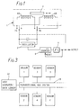
- the sensor head 1 of Figure 1 measures displacement by converting it into a variation in the frequency of an oscillator 2.
- the displacement to be measured causes movement of a core of ferromagnetic material 4, such as radiometal alloy, within a pair of inductor coils 6A and 6B, thus causing a variation in the inductance thereof.
- Each of the coils 6A and 6B can form part of the tuned circuit of an oscillator 2, and thus the frequency of oscillation varies in accordance with the displacement to be measured.
- the variation of frequency with displacement is not linear, but this non-linearity may be corrected within the processing circuitry.
- the two switches 7A and 7B which switch between the two coils 6A and 6B and the first counter8 which counts the output cycles of the oscillator 2 are shown in Figure 1 to be outside the sensor head 1, in another embodiment these items may be incorporated into the sensor head.
- the two coil system of Figure 1 is a differential system in which the magnetic material 4 moves out of one coil 6A into a similar coil 6B mounted coaxially such that as the inductance of one inductor is reduced, the inductance of the other is increased, and the difference in frequencies is calculated subsequently in a micro-processor.
- the output cycles of the oscillator 2, in Figure 1, are counted in a first counter 8. After n cycles of the oscillation have been counted, the counter 8 produces an output pulse 9.
- the pulse 9 operates the two switches 7A and 7B which switch between the two coils 6A and 6B of the tuned circuit of the oscillator 2, to disconnect one of the coils 6A and 6B and connect the other coil to the tuned circuit.
- the output pulse 9 from the first counter 8 also resets the counter 8 to zero and inhibits the counter's operation for a period of time sufficient to allow the frequency of the oscillator 2 to stabilize, after which the counter 8 proceeds to count n cycles of the frequency due to the connected coil 6A or 6B.
- the time between the trailing edge of one output pulse from the first counter 8, and the leading edge of the subsequent output pulse defines the period of n cycles of the oscillator for each coil 6A and 6B, and thus the frequencies of oscillation corresponding to each coil.
- the difference between the periods of n cycles corresponding to each coil is a function of the displacement to be measured.
- the output pulse 9 from the first counter 8 is applied to a second counter 12 of Figure 2, which is driven from a high frequency crystal clock 10.
- the second counter 12 is allowed to count cycles from the high frequency clock 10 until the leading edge of the subsequent output pulse from the first counter 8 is received.
- the count from the second counter 12, which represents the period of n cycles of the oscillator 2, and thus the frequency of oscillation, is loaded into the microprocessor 14 and the second counter 12 is reset to zero.
- the micro-processor 14 thus converts the counts of the counter 12 into a positional reading, corrected for non-linearity of the frequency change with displacement and for the individual characteristics of the sensor head, and interpolates between stored values in the memory.
- the output from the micro-processor is connected to a bi-directional interface/bus 18 via drivers 20, for example the RS485 or RS232 system. It is possible to process some of the data obtained, in the micro-processor, for example to determine maximum, minimum and mean results over a period, or to take measurements at predetermined times, thus reducing the amount of data needed to be transmitted over the bus system.
- the measuring or sensor head 1 is attached by a long lead to a connector containing the processing circuitry, i.e. the elements 10, 12, 14, 16 and 20.
- This connector is designed to be plugged directly to other connectors of other sensors to build up the bi-directional bus 18 connecting the sensors to a host computer/data logger 22 as shown in Figure 3.
- the connector comprises a plastics housing for the electronics, including a lead connected to the sensor head. Alternatively a metal housing can be used for protection against radio-frequency interference.
- a D-type input socket and a D-type output socket provide for the plug connection of successive units.
- the connector comprises a metal housing which is sealed to at least IP60 standard.
- the connector may be connected directly to other similar connectors without the need for lead linkage with complementary connectors at each end, to form a single assembly mountable on the apparatus over which the individual sensor heads are distributed.
- Each of the sensors is provided with a unique ID programmed into it at the factory so that the host computer can identify which sensor is in which position on the bus.
- the memory (16) of Figure 2 in which the sensor calibration coefficients are stored, and the unique ID allocated to each sensor, are contained in a separate unit, which may be plugged into the connector housing the processing circuitry. As such, any damage occurring to the associated sensor head or lead would not automatically require the entire unit to be replaced. Also, the memory (16) may be physically implemented in, for example, the form of a key and need not be re-programmable.
- the frequencies corresponding to each coil have been obtained, it is possible to take either the ratio or difference of the two frequencies to calculate the displacement measured by the sensor.
- the counts corresponding to the two frequencies are separately transferred from the counter 12 to the microprocessor 14, which then calculates the ratio and compares this with the stored values in ROM 16.
- the timing of the operation of the switches 7A and 7B, and the timing of the commencement of the counting of n cycles of the oscillator 2 for each coil 6A and 6B, can be controlled by the microprocessor 14.
Landscapes
- Physics & Mathematics (AREA)
- General Physics & Mathematics (AREA)
- Engineering & Computer Science (AREA)
- Technology Law (AREA)
- Measurement Of Length, Angles, Or The Like Using Electric Or Magnetic Means (AREA)
- Transmission And Conversion Of Sensor Element Output (AREA)
- Measuring Fluid Pressure (AREA)
- Measuring Pulse, Heart Rate, Blood Pressure Or Blood Flow (AREA)
- Switches That Are Operated By Magnetic Or Electric Fields (AREA)
- Measuring Frequencies, Analyzing Spectra (AREA)
- Stabilization Of Oscillater, Synchronisation, Frequency Synthesizers (AREA)
- Electronic Switches (AREA)
- Length Measuring Devices Characterised By Use Of Acoustic Means (AREA)
- Measurement Of Mechanical Vibrations Or Ultrasonic Waves (AREA)
Applications Claiming Priority (2)
| Application Number | Priority Date | Filing Date | Title |
|---|---|---|---|
| GB919127112A GB9127112D0 (en) | 1991-12-20 | 1991-12-20 | Smart displacement sensor |
| GB9127112 | 1991-12-20 |
Publications (3)
| Publication Number | Publication Date |
|---|---|
| EP0549285A2 true EP0549285A2 (fr) | 1993-06-30 |
| EP0549285A3 EP0549285A3 (en) | 1993-12-01 |
| EP0549285B1 EP0549285B1 (fr) | 1996-09-25 |
Family
ID=10706628
Family Applications (1)
| Application Number | Title | Priority Date | Filing Date |
|---|---|---|---|
| EP92311610A Expired - Lifetime EP0549285B1 (fr) | 1991-12-20 | 1992-12-18 | Appareil pour mesurer le déplacement par variation en fréquence d'un oscillateur |
Country Status (8)
| Country | Link |
|---|---|
| US (1) | US5726567A (fr) |
| EP (1) | EP0549285B1 (fr) |
| JP (1) | JP3349739B2 (fr) |
| KR (1) | KR930013677A (fr) |
| AT (1) | ATE143487T1 (fr) |
| DE (1) | DE69214110T2 (fr) |
| ES (1) | ES2092063T3 (fr) |
| GB (2) | GB9127112D0 (fr) |
Cited By (2)
| Publication number | Priority date | Publication date | Assignee | Title |
|---|---|---|---|---|
| EP0708396A1 (fr) * | 1994-10-21 | 1996-04-24 | Elsag International N.V. | Mise d'accord automatique d'un circuit de contrÔle de position pour un servo-mécanisme |
| WO2017067840A1 (fr) * | 2015-10-22 | 2017-04-27 | Robert Bosch Gmbh | Capteur d'angle de rotation |
Families Citing this family (16)
| Publication number | Priority date | Publication date | Assignee | Title |
|---|---|---|---|---|
| JP3006524B2 (ja) * | 1996-12-25 | 2000-02-07 | 日本電気株式会社 | 双方向遷移数削減インターフェース回路 |
| US6175928B1 (en) | 1997-12-31 | 2001-01-16 | Intel Corporation | Reducing timing variance of signals from an electronic device |
| US6174922B1 (en) * | 1998-05-11 | 2001-01-16 | Eli Lilly And Company | Sulphonamide derivatives |
| US6470751B1 (en) | 1999-02-20 | 2002-10-29 | Lg Electronics Inc. | Vibration detecting apparatus and method thereof |
| US6351117B1 (en) | 1999-09-20 | 2002-02-26 | Balluff, Inc. | Method and apparatus for generating transducer output pulses compensated for component variations |
| US6583630B2 (en) * | 1999-11-18 | 2003-06-24 | Intellijoint Systems Ltd. | Systems and methods for monitoring wear and/or displacement of artificial joint members, vertebrae, segments of fractured bones and dental implants |
| IL134026A (en) * | 2000-01-13 | 2005-11-20 | Visonic Ltd | Circuitry for signal measurement |
| IL135730A (en) * | 2000-04-18 | 2004-05-12 | Visonic Ltd | Displacement sensor |
| KR100828128B1 (ko) * | 2006-07-20 | 2008-05-09 | 에이디반도체(주) | 시분할 복수 주파수를 이용하는 정전용량 검출방법 및검출장치 |
| US20080032797A1 (en) * | 2006-07-24 | 2008-02-07 | Nds Limited | Combining broadcast sporting events and computer-based gaming |
| US7719263B2 (en) * | 2006-11-22 | 2010-05-18 | Zf Friedrichshafen Ag | Inductive position measuring device or goniometer |
| KR100928339B1 (ko) * | 2007-09-03 | 2009-11-30 | 문병균 | 멀티 스캔을 이용한 변위측정방법 및 변위측정용 신호조절기 |
| DE102009004688A1 (de) | 2009-01-12 | 2010-07-22 | Beb Industrie-Elektronik Ag | Vorrichtung zum Feststellen einer Dicke oder Dickenvariation eines flachen Gegenstandes |
| DE102009005171B4 (de) | 2009-01-15 | 2025-05-08 | Beb Industrie-Elektronik Ag | Vorrichtung und Verfahren zum Nachweis von reflektiertem und/oder emittiertem Licht eines Gegenstandes |
| DE202011000405U1 (de) * | 2011-02-22 | 2012-05-23 | Rollax Gmbh & Co. Kg | Induktive Wegmesseinrichtung |
| CN115962794B (zh) * | 2021-10-13 | 2025-06-03 | 大庆油田有限责任公司 | 一种单根引线位移传感器 |
Family Cites Families (17)
| Publication number | Priority date | Publication date | Assignee | Title |
|---|---|---|---|---|
| BE621772A (fr) * | 1962-04-02 | |||
| US3790910A (en) * | 1972-04-21 | 1974-02-05 | Garrett Corp | Conditioning circuit and method for variable frequency sensor |
| US4041470A (en) * | 1976-01-16 | 1977-08-09 | Industrial Solid State Controls, Inc. | Fault monitoring and reporting system for trains |
| DE2940083A1 (de) * | 1979-10-03 | 1981-04-16 | Daimler-Benz Ag, 7000 Stuttgart | Frequenzgenerator |
| US4335442A (en) * | 1979-12-20 | 1982-06-15 | American Can Company | Synchronous oscillator demodulator system |
| GB2097536A (en) * | 1981-04-24 | 1982-11-03 | Wolfendale Peter Caleb Frederi | Correcting transducer measurements |
| US4401351A (en) * | 1981-09-28 | 1983-08-30 | Advant Corporation | Expandable card cage |
| DE3276673D1 (en) * | 1981-11-10 | 1987-08-06 | Sentron V O F | Catheter sensor and memory unit |
| JPS58120137A (ja) * | 1982-01-13 | 1983-07-16 | Terumo Corp | 電子体温計 |
| FR2600788B1 (fr) * | 1986-06-25 | 1988-11-18 | Mauron Christian | Procede et dispositif de visualisation de l'ecoulement d'un intervalle de temps |
| US4831558A (en) * | 1986-08-26 | 1989-05-16 | The Slope Indicator Company | Digitally based system for monitoring physical phenomena |
| GB8626270D0 (en) * | 1986-11-04 | 1986-12-03 | Renishaw Plc | Displacement transducers |
| US4930096A (en) * | 1987-01-22 | 1990-05-29 | Man Design Co., Ltd. | Data-transmitting apparatus having connecting plug |
| JPS6421306U (fr) * | 1987-07-30 | 1989-02-02 | ||
| JPS6421305U (fr) * | 1987-07-30 | 1989-02-02 | ||
| JPS6439502A (en) * | 1987-08-05 | 1989-02-09 | Man Design Co | Length measuring instrument |
| US5006797A (en) * | 1989-03-02 | 1991-04-09 | Smith William L | Electromagnetic sensor assembly |
-
1991
- 1991-12-20 GB GB919127112A patent/GB9127112D0/en active Pending
-
1992
- 1992-12-18 AT AT92311610T patent/ATE143487T1/de not_active IP Right Cessation
- 1992-12-18 ES ES92311610T patent/ES2092063T3/es not_active Expired - Lifetime
- 1992-12-18 JP JP35550592A patent/JP3349739B2/ja not_active Expired - Lifetime
- 1992-12-18 DE DE69214110T patent/DE69214110T2/de not_active Expired - Lifetime
- 1992-12-18 GB GB9226456A patent/GB2262614B/en not_active Expired - Lifetime
- 1992-12-18 EP EP92311610A patent/EP0549285B1/fr not_active Expired - Lifetime
- 1992-12-21 KR KR1019920024850A patent/KR930013677A/ko not_active Withdrawn
-
1995
- 1995-04-03 US US08/415,571 patent/US5726567A/en not_active Expired - Lifetime
Cited By (3)
| Publication number | Priority date | Publication date | Assignee | Title |
|---|---|---|---|---|
| EP0708396A1 (fr) * | 1994-10-21 | 1996-04-24 | Elsag International N.V. | Mise d'accord automatique d'un circuit de contrÔle de position pour un servo-mécanisme |
| WO2017067840A1 (fr) * | 2015-10-22 | 2017-04-27 | Robert Bosch Gmbh | Capteur d'angle de rotation |
| US10895475B2 (en) | 2015-10-22 | 2021-01-19 | Robert Bosch Gmbh | Angular position sensor |
Also Published As
| Publication number | Publication date |
|---|---|
| EP0549285B1 (fr) | 1996-09-25 |
| EP0549285A3 (en) | 1993-12-01 |
| GB9226456D0 (en) | 1993-02-10 |
| GB2262614B (en) | 1995-03-15 |
| DE69214110D1 (de) | 1996-10-31 |
| ATE143487T1 (de) | 1996-10-15 |
| US5726567A (en) | 1998-03-10 |
| JPH05248804A (ja) | 1993-09-28 |
| DE69214110T2 (de) | 1997-04-03 |
| KR930013677A (ko) | 1993-07-22 |
| GB2262614A (en) | 1993-06-23 |
| ES2092063T3 (es) | 1996-11-16 |
| JP3349739B2 (ja) | 2002-11-25 |
| GB9127112D0 (en) | 1992-02-19 |
Similar Documents
| Publication | Publication Date | Title |
|---|---|---|
| US5726567A (en) | Network-connectable displacement sensor with stored ID | |
| US5412317A (en) | Position detector utilizing absolute and incremental position sensors in combination | |
| US5181423A (en) | Apparatus for sensing and transmitting in a wireless manner a value to be measured | |
| US5438274A (en) | Linear position sensor using a coaxial resonant cavity | |
| US5425073A (en) | Analyzer circuit an inductive position sensor | |
| US4309909A (en) | Crystal stabilized voltage to frequency converter with digital calibration for flowmeters | |
| GB2233459A (en) | Linearising and calibrating surface characteristic measuring apparatus | |
| US4377851A (en) | Method for calibrating a transducer for converting pressure variation to frequency variation | |
| EP0230088A1 (fr) | Appareil d'amplification et d'amélioration d'un capteur utilisant des techniques numériques | |
| US4446447A (en) | Circuit for converting pressure variation to frequency variation | |
| US6242906B1 (en) | Systems and methods for calibrating an absolute position encoder | |
| US5331277A (en) | Inductive divider position sensor with fixed and variable impedance inductors | |
| US4364045A (en) | Digitized displacement transducer | |
| US4972722A (en) | Magnetic inductive flow meter | |
| US6369563B1 (en) | Method for high resolution measurement of a position | |
| JPH04221702A (ja) | 誘導形位置発生器 | |
| CA2136760A1 (fr) | Transducteur numerique | |
| WO1987000951A1 (fr) | Systemes d'inductance | |
| US5053769A (en) | Fast response digital interface apparatus and method | |
| CA1240370A (fr) | Dispositif et methode d'interfacage de transducteurs | |
| CA2245884C (fr) | Procede de mesure d'une position a haute resolution | |
| US4335440A (en) | Signal enhancement circuit | |
| JPH07502338A (ja) | 同軸共振空洞を使用した線形位置センサー | |
| JP2742829B2 (ja) | 原点回路 | |
| CN85101440B (zh) | 具有计算机的位移测量设备 |
Legal Events
| Date | Code | Title | Description |
|---|---|---|---|
| PUAI | Public reference made under article 153(3) epc to a published international application that has entered the european phase |
Free format text: ORIGINAL CODE: 0009012 |
|
| AK | Designated contracting states |
Kind code of ref document: A2 Designated state(s): AT BE CH DE DK ES FR IE IT LI NL PT SE |
|
| PUAL | Search report despatched |
Free format text: ORIGINAL CODE: 0009013 |
|
| AK | Designated contracting states |
Kind code of ref document: A3 Designated state(s): AT BE CH DE DK ES FR IE IT LI NL PT SE |
|
| 17P | Request for examination filed |
Effective date: 19940504 |
|
| RAP1 | Party data changed (applicant data changed or rights of an application transferred) |
Owner name: SOLARTRON METROLOGY LIMITED |
|
| RAP1 | Party data changed (applicant data changed or rights of an application transferred) |
Owner name: SOLARTRON GROUP LIMITED |
|
| 17Q | First examination report despatched |
Effective date: 19950420 |
|
| GRAH | Despatch of communication of intention to grant a patent |
Free format text: ORIGINAL CODE: EPIDOS IGRA |
|
| GRAH | Despatch of communication of intention to grant a patent |
Free format text: ORIGINAL CODE: EPIDOS IGRA |
|
| RAP3 | Party data changed (applicant data changed or rights of an application transferred) |
Owner name: SOLARTRON GROUP LIMITED |
|
| GRAA | (expected) grant |
Free format text: ORIGINAL CODE: 0009210 |
|
| ITF | It: translation for a ep patent filed | ||
| AK | Designated contracting states |
Kind code of ref document: B1 Designated state(s): AT BE CH DE DK ES FR IE IT LI NL PT SE |
|
| PG25 | Lapsed in a contracting state [announced via postgrant information from national office to epo] |
Ref country code: NL Free format text: LAPSE BECAUSE OF FAILURE TO SUBMIT A TRANSLATION OF THE DESCRIPTION OR TO PAY THE FEE WITHIN THE PRESCRIBED TIME-LIMIT Effective date: 19960925 Ref country code: LI Effective date: 19960925 Ref country code: DK Effective date: 19960925 Ref country code: CH Effective date: 19960925 Ref country code: BE Effective date: 19960925 Ref country code: AT Effective date: 19960925 |
|
| REF | Corresponds to: |
Ref document number: 143487 Country of ref document: AT Date of ref document: 19961015 Kind code of ref document: T |
|
| REF | Corresponds to: |
Ref document number: 69214110 Country of ref document: DE Date of ref document: 19961031 |
|
| REG | Reference to a national code |
Ref country code: IE Ref legal event code: FG4D Free format text: 69989 |
|
| REG | Reference to a national code |
Ref country code: ES Ref legal event code: FG2A Ref document number: 2092063 Country of ref document: ES Kind code of ref document: T3 |
|
| PG25 | Lapsed in a contracting state [announced via postgrant information from national office to epo] |
Ref country code: IE Free format text: LAPSE BECAUSE OF NON-PAYMENT OF DUE FEES Effective date: 19961218 |
|
| PG25 | Lapsed in a contracting state [announced via postgrant information from national office to epo] |
Ref country code: SE Effective date: 19961225 |
|
| PG25 | Lapsed in a contracting state [announced via postgrant information from national office to epo] |
Ref country code: PT Effective date: 19961226 |
|
| ET | Fr: translation filed | ||
| NLV1 | Nl: lapsed or annulled due to failure to fulfill the requirements of art. 29p and 29m of the patents act | ||
| REG | Reference to a national code |
Ref country code: CH Ref legal event code: PL |
|
| PLBE | No opposition filed within time limit |
Free format text: ORIGINAL CODE: 0009261 |
|
| STAA | Information on the status of an ep patent application or granted ep patent |
Free format text: STATUS: NO OPPOSITION FILED WITHIN TIME LIMIT |
|
| 26N | No opposition filed | ||
| REG | Reference to a national code |
Ref country code: FR Ref legal event code: TP |
|
| REG | Reference to a national code |
Ref country code: FR Ref legal event code: TP |
|
| REG | Reference to a national code |
Ref country code: ES Ref legal event code: PC2A |
|
| PGFP | Annual fee paid to national office [announced via postgrant information from national office to epo] |
Ref country code: IT Payment date: 20101224 Year of fee payment: 19 |
|
| PGFP | Annual fee paid to national office [announced via postgrant information from national office to epo] |
Ref country code: DE Payment date: 20101215 Year of fee payment: 19 |
|
| PGFP | Annual fee paid to national office [announced via postgrant information from national office to epo] |
Ref country code: FR Payment date: 20111219 Year of fee payment: 20 |
|
| REG | Reference to a national code |
Ref country code: DE Ref legal event code: R071 Ref document number: 69214110 Country of ref document: DE |
|
| REG | Reference to a national code |
Ref country code: DE Ref legal event code: R071 Ref document number: 69214110 Country of ref document: DE |
|
| PGFP | Annual fee paid to national office [announced via postgrant information from national office to epo] |
Ref country code: ES Payment date: 20120116 Year of fee payment: 20 |
|
| REG | Reference to a national code |
Ref country code: ES Ref legal event code: FD2A Effective date: 20130723 |
|
| PG25 | Lapsed in a contracting state [announced via postgrant information from national office to epo] |
Ref country code: ES Free format text: LAPSE BECAUSE OF EXPIRATION OF PROTECTION Effective date: 20121219 |