EP0549417B1 - Verfahren und Anordnung zur Automatisierung von Laser-Dopplergeschwindigkeitsmessern mit vorwärts gerichteter Lichtstreuung - Google Patents
Verfahren und Anordnung zur Automatisierung von Laser-Dopplergeschwindigkeitsmessern mit vorwärts gerichteter Lichtstreuung Download PDFInfo
- Publication number
- EP0549417B1 EP0549417B1 EP92403430A EP92403430A EP0549417B1 EP 0549417 B1 EP0549417 B1 EP 0549417B1 EP 92403430 A EP92403430 A EP 92403430A EP 92403430 A EP92403430 A EP 92403430A EP 0549417 B1 EP0549417 B1 EP 0549417B1
- Authority
- EP
- European Patent Office
- Prior art keywords
- photodetector
- counting rate
- measurement
- spiral
- point
- Prior art date
- Legal status (The legal status is an assumption and is not a legal conclusion. Google has not performed a legal analysis and makes no representation as to the accuracy of the status listed.)
- Expired - Lifetime
Links
Images


Classifications
-
- G—PHYSICS
- G01—MEASURING; TESTING
- G01S—RADIO DIRECTION-FINDING; RADIO NAVIGATION; DETERMINING DISTANCE OR VELOCITY BY USE OF RADIO WAVES; LOCATING OR PRESENCE-DETECTING BY USE OF THE REFLECTION OR RERADIATION OF RADIO WAVES; ANALOGOUS ARRANGEMENTS USING OTHER WAVES
- G01S17/00—Systems using the reflection or reradiation of electromagnetic waves other than radio waves, e.g. lidar systems
- G01S17/02—Systems using the reflection of electromagnetic waves other than radio waves
- G01S17/50—Systems of measurement based on relative movement of target
-
- G—PHYSICS
- G01—MEASURING; TESTING
- G01P—MEASURING LINEAR OR ANGULAR SPEED, ACCELERATION, DECELERATION, OR SHOCK; INDICATING PRESENCE, ABSENCE, OR DIRECTION, OF MOVEMENT
- G01P5/00—Measuring speed of fluids, e.g. of air stream; Measuring speed of bodies relative to fluids, e.g. of ship, of aircraft
- G01P5/26—Measuring speed of fluids, e.g. of air stream; Measuring speed of bodies relative to fluids, e.g. of ship, of aircraft by measuring the direct influence of the streaming fluid on the properties of a detecting optical wave
Definitions
- the present invention relates to anemometry, that is to say to the measurement of the local speed at a large number of points of a fluid flow, in particular gaseous, by means of a laser velocimeter with Doppler effect.
- Current Doppler laser anemometry devices include a transmitting head capable of emitting two laser beams of different colors which intersect at the point of measurement of the local speed of the fluid flow and a receiving head comprising a photodetector, such as a photomultiplier, which observes the measurement point.
- Velocimeters operating in rear broadcast mode have the advantage of easily ensuring, in particular in the case where the transmission part and the reception part are in the same unit, the synchronization of the movement of the transmission device and of the reception device, which ensures that the photodetector of the receiving device is aimed at the point where the two laser beams of the transmitting device intersect.
- velocimeters operating in front scattering mode, they have the advantage of allowing a collection of the light scattered by the measurement point much higher than the rear scattering mode.
- Dopler effect laser velocimeters operating in the forward scattering mode include a table for the emission device which carries one or two emission optical heads emitting two laser beams, the lasers themselves being able to be located remotely by fixed position and supply the optical head or heads with optical fibers, and a table carrying the photodetector receiving head, these two tables being arranged on either side of the measurement volume, in fact on either side of two windows opposite optics provided in a conduit in which the flow of the fluid to be observed occurs.
- bracket in the shape of an inverted U, very rigid to guarantee high precision of the movement synchronism, which ensures simultaneous movement of the two tables, namely the one carrying the optical heads and the one carrying the photodetector.
- the invention aims to achieve the automation of the movement of the receiving head so that the photodetector (s) thereof aim exactly at the measurement point where the laser beams of the two optical heads of the laser beam emitting device cross when the table who carries these heads moves in order to move the measuring point.
- Such an automatic system makes it possible to carry out measurements of the speed of the flow of a fluid, even when it is impossible to ensure the seeding of the flow with particles with high diffusion power, in particular in order to avoid to pollute the flow, the flow itself comprising only very few particles, even of small dimensions, and to verify these measurements, even in test veins of large dimensions, for example greater than one meter on a side in section and when it is desired to measure the speed at a large number of points, for example of the order of 1000 points.
- the adjustment of the focusing may require for each point at least five minutes, if not more.
- the calculating device associated with the output of the photomultiplier 7 determines, for each stop position of the receiving device 7, the reduced counting rate, which is zero when the photodetector of the device 7 does not aim, in the measurement area 6, at the measurement volume 9, but which has a non-zero value when the field 10 seen by the photodetector of the device 7 at least partially overlaps the measurement volume 9, the reduced counting rate being maximum when the entire measurement volume 9 is covered by the field 10 seen by the photodetector of the device 7.
- the search for the position of the photodetector of the device 7 in order to optimize its position takes place in a plane perpendicular to the optical axis 7a of the photodetector.
- N * N / U formula in which N is the frequency of acquisition of information from the particles passing through the measurement volume 9 and whose speed has been validated and U is the average of the absolute speeds of the particles recorded during the measurement at a point given by the formula (1).
- the reduced count rate is calculated only on a component of the speed in a given direction. It is interesting to choose the component of the velocity which is close to the velocity vector of the flow at this point.
- the definition thereof is based on the average of the absolute speeds of each particle, to ensure that the counting is independent of the direction of passage of the particle targeted in the measurement volume; more particularly, in a flow zone in which the average speed would be zero, but in which the speed fluctuations would change sign, the definition of the reduced counting rate given previously only accounts for the frequency of the passages of particles in the measurement volume, whatever their direction and direction.
- the reduced counting rate is maximum.
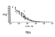
- N m * the rate of reduced count measured during movement of the table supporting the reception device 7, it can be seen that the latter increases as the field 9 seen by the photodetector overlaps more and more the measurement volume 10 and it reaches precisely the maximum value N M * when, as indicated above, field 9 covers the volume l0
- the method according to the invention for automating the movement of the device 7 comprises a prior phase or sequence and two successive operational phases or sequences.
- the preliminary phase or sequence consists in initializing the parameters.
- the operator firstly adjusts the position of the photodetector of the receiving device 7 on the measurement volume, that is to say on the crossing point 6b of the beams.
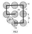
- the search for the maximum reduced counting rate is carried out automatically, the photodetector describing, by setting in motion the movement table of the receiving device 7, a spiral of the type illustrated at 11 in FIG. 2, that is to say a spiral with successive rectilinear sections at right angles from a starting point 11a and widening to a finishing point 11b.
- This spiral is described with a very small step since, contrary to what is illustrated in FIG. 2, from the start at point 11a the photodetector is already adjusted to the point of crossing of the beams.
- the reduced count rate is recorded.
- the photodetector of the device 7 is positioned at the point of the spiral which has the maximum reduced counting rate, namely N M * . Therefore, operational operation can be carried out in two successive sequences.
- the sequence or phase No. 1 of partial automatic focusing on the current point of the measurement volume is illustrated in FIG. 2, assuming that initially no speed information is validated and that we are at the starting point 11a spiral 11.
- the sequence No. 1 begins and continues by causing the photodetector of the receiving device 7 to move in a spiral of constant motion by means of its displacement table.
- the spiral 11, comprises successive rectilinear courses rectilinear at right angles and it widens until it is stopped at point 11b as soon as the calculated reduced counting rate is different from zero.
- the step dl of the spiral 11 in the case of this partial automatic focusing sequence is chosen so as to obtain an optimal scanning of the space.
- the position of two fields is therefore used, namely the field 10 seen by the photodetector and the field of the measurement volume 9 (FIGS. 1 and 3), their centers, respectively 9a and 9b, being separated by the distance r.
- the second final automatic focusing sequence on the current point is the replica of the previous partial automatic focusing sequence, namely it is carried out in a spiral with rectilinear sections at right angles with dilation of the spiral, that is to say similar to that illustrated in 11 in FIG. 2, but the pitch of the new spiral is equal to a fraction of the diameter D m of the measurement volume at the crossing point 6b of the laser beams.
- This second spiral movement sequence is stopped as soon as the measured reduced counting rate reaches a large percentage of the maximum reduced counting rate N M * , namely when N * > k N M * , k being a numerical coefficient taken for example equal to 70%, a value which appears satisfactory in most cases, but of course we could predict a value of k somewhat different from 70%, for example between 70% and 85%.
- the device emits a signal, for example sound or light, which attracts the attention of the operator, who then manually performs the initial adjustment, then again entrusts the operation to the process and automatic focusing device according to the invention and which have just been described in detail above.
- a signal for example sound or light
- the method and the automation device according to the invention were applied to the component of the axial velocities of the flow.
- the method according to the invention can operate with a laser anemometer with one, two or three components.
- the invention can be extended to the case where the photodetector is not located in the optical axis of the laser beams, but has an offset angle with said optical axis.
- the method and the device according to the invention can also be used in a more general framework for detecting the coincidence of the measurement volumes with the use of several colors, which is the case with the three-component laser velocimeter with three pairs of beams of different wavelengths (for example corresponding to the colors green, blue and purple).
- the three-component laser velocimeter with three pairs of beams of different wavelengths (for example corresponding to the colors green, blue and purple).
- the automation of focusing is carried out. successively on each measurement volume of each different color pair, which makes it possible to know the respective position of each measurement volume.
Landscapes
- Engineering & Computer Science (AREA)
- Physics & Mathematics (AREA)
- General Physics & Mathematics (AREA)
- Electromagnetism (AREA)
- Multimedia (AREA)
- Aviation & Aerospace Engineering (AREA)
- Computer Networks & Wireless Communication (AREA)
- Radar, Positioning & Navigation (AREA)
- Remote Sensing (AREA)
- Investigating Or Analysing Materials By Optical Means (AREA)
- Optical Radar Systems And Details Thereof (AREA)
Claims (3)
- Automatisierungsverfahren für Laser-Doppler-Geschwindigkeitsmesser nach der Methode der Vorwärtsstrahlung, bestehend aus einer von einer ersten verschiebbaren Platte getragenen Strahlungsvorrichtung für Laserstrahlen, und einer von einer zweiten verschiebbaren Platte getragenen Empfangsvorrichtung mit Lichtdetektor, gekennzeichnet durch: die Anwendung einer sogenannten reduzierten Impulsrate N*, welche definiert ist als der Quotient der Akquisitionsfrequenz N der Informationen, welche aus den Partikeln gewonnen wurden, die ein Meßvolumen durchlaufen und deren Geschwindigkeit validiert wurde, und des Mittelwertes U der während der Messung an einem Punkt aufgezeichneten absoluten Geschwindigkeiten |Ui| der Partikel, definiert durch die Formel
 a) eine partielle automatische Fokalisierungsphase, welche darin besteht, den Lichtdetektor anhand seiner Verschiebungsplatte gemäß einer Spirale mit geradlinigen aufeinanderfolgenden Querschnitten mit rechtem Winkel, der sich vom Ausgangspunkt aus vergrößert, zu verschieben, wobei die aufeinanderfolgenden Verschiebungen des Lichtdetektors gemäß einem ersten konstanten Schritt erfolgen, bis die kalkulierte reduzierte Impulsrate von O abweicht, undb) eine abschließende Fokalisierungsphase oder -sequenz, welche auf die vorangegangene Phase folgt und gemäß einer ähnlichen Spirale erfolgt, wobei sich der zweite Schritt jedoch vom ersten darin unterscheidet, daß er einem Bruchstück des Meßvolumendurchmessers entspricht, wobei die Verschiebung des Lichtdetektors anhält, sobald die kalkulierte reduzierte Impulsrate die zuvor bestimmte maximale reduzierte Impulsrate um 50 % oder mehr überschreitet;
 - Verfahren gemäß Anspruch 1, dadurch gekennzeichnet, daß die abschließende Fokalisierungsphase oder -sequenz beendet wird, wenn die errechnete reduzierte Impulsrate zwischen 70 und 85 % der maximalen reduzierten Impulsrate beträgt.
- Vorrichtung für die Anwendung des Verfahrens gemäß Anspruch 1 oder 2, bestehend aus einer Vorrichtung (2) zur Ausstrahlung von Laserstrahlen (4, 5), getragen von einer ersten verschiebbaren Platte, um die Änderung des Meßpunktes (6a) im Meßvolumen (6) zu ermöglichen; einer Empfangsvorrichtung (7) mit mindestens einem Lichtdetektor, getragen von einer zweiten verschiebbaren Platte; Hilfsmitteln zum Verschieben der zweiten Platte synchron mit der ersten Platte, dadurch gekennzeichnet, daß diese letztgenannten Hilfsmittel aus Hilfsmitteln zur Ermittlung der erwähnten reduzierten Impulsrate bestehen; Hilfsmitteln zur Gewährleistung der Verschiebung der zweiten Platte gemäß der ersten (11) und der zweiten Spirale mit aufeinanderfolgenden geradlinigen Querschnitten mit rechtem Winkel, welche sich nach und nach vergrößert, wobei der erste und der zweite Verschiebungsschritt konstant ist und die Verschiebung gemäß der ersten Spirale gemäß dem ersten Schritt (d₁) bis zum Erzielen einer von Null abweichenden reduzierten Impulsrate erfolgt, während die Verschiebung gemäß der zweiten Spirale bis zum Erreichen einer gemessenen reduzierten Impulsrate, welche die zuvor ermittelte maximale reduzierte Impulsrate um 50 % oder mehr überschreitet, um somit zufriedenstellende Messungen zu ermöglichen.
Applications Claiming Priority (2)
| Application Number | Priority Date | Filing Date | Title |
|---|---|---|---|
| FR9116183 | 1991-12-26 | ||
| FR9116183A FR2685783B1 (fr) | 1991-12-26 | 1991-12-26 | Procede et dispositif pour l'automatisation des velocimetres laser a effet doppler fonctionnant en diffusion avant. |
Publications (2)
| Publication Number | Publication Date |
|---|---|
| EP0549417A1 EP0549417A1 (de) | 1993-06-30 |
| EP0549417B1 true EP0549417B1 (de) | 1996-05-01 |
Family
ID=9420538
Family Applications (1)
| Application Number | Title | Priority Date | Filing Date |
|---|---|---|---|
| EP92403430A Expired - Lifetime EP0549417B1 (de) | 1991-12-26 | 1992-12-16 | Verfahren und Anordnung zur Automatisierung von Laser-Dopplergeschwindigkeitsmessern mit vorwärts gerichteter Lichtstreuung |
Country Status (4)
| Country | Link |
|---|---|
| EP (1) | EP0549417B1 (de) |
| DE (1) | DE69210377T2 (de) |
| DK (1) | DK0549417T3 (de) |
| FR (1) | FR2685783B1 (de) |
Families Citing this family (1)
| Publication number | Priority date | Publication date | Assignee | Title |
|---|---|---|---|---|
| DE19736172B4 (de) * | 1997-08-20 | 2004-02-05 | Palas Gmbh Partikel- Und Lasermesstechnik | Verfahren und Vorrichtung zur Analyse von Teilchen |
Citations (1)
| Publication number | Priority date | Publication date | Assignee | Title |
|---|---|---|---|---|
| EP0458276A2 (de) * | 1990-05-21 | 1991-11-27 | Canon Kabushiki Kaisha | Dopplergeschwindigkeitsmesser |
Family Cites Families (7)
| Publication number | Priority date | Publication date | Assignee | Title |
|---|---|---|---|---|
| US458276A (en) * | 1891-08-25 | Machine for turning spoke-tenons | ||
| US4148585A (en) * | 1977-02-11 | 1979-04-10 | The United States Of America As Represented By The Department Of Health, Education & Welfare | Three dimensional laser Doppler velocimeter |
| US4167329A (en) * | 1977-12-12 | 1979-09-11 | Raytheon Company | Focussed doppler radar |
| DE3125685A1 (de) * | 1981-06-30 | 1983-01-13 | Armin Dr.-Ing. 4010 Hilden Schnettler | Vorrichtung zur optoelektronischen laser-doppler-messvolumenpositionierung |
| US4632548A (en) * | 1985-01-18 | 1986-12-30 | The United States Of America As Represented By The Administrator Of The National Aeronautics And Space Administration | Projection lens scanning laser velocimeter system |
| JP2523633B2 (ja) * | 1987-05-13 | 1996-08-14 | 株式会社日立製作所 | レ−ザレ−ダの走査方法 |
| FR2670293B1 (fr) * | 1990-12-05 | 1994-05-06 | Etat Francais Delegue Armement | Procede et dispositif pour la mesure de la vitesse d'un ecoulement de fluide ou de particules. |
-
1991
- 1991-12-26 FR FR9116183A patent/FR2685783B1/fr not_active Expired - Fee Related
-
1992
- 1992-12-16 DK DK92403430T patent/DK0549417T3/da active
- 1992-12-16 EP EP92403430A patent/EP0549417B1/de not_active Expired - Lifetime
- 1992-12-16 DE DE1992610377 patent/DE69210377T2/de not_active Expired - Fee Related
Patent Citations (1)
| Publication number | Priority date | Publication date | Assignee | Title |
|---|---|---|---|---|
| EP0458276A2 (de) * | 1990-05-21 | 1991-11-27 | Canon Kabushiki Kaisha | Dopplergeschwindigkeitsmesser |
Also Published As
| Publication number | Publication date |
|---|---|
| EP0549417A1 (de) | 1993-06-30 |
| DE69210377T2 (de) | 1996-09-19 |
| FR2685783B1 (fr) | 1994-03-18 |
| FR2685783A1 (fr) | 1993-07-02 |
| DE69210377D1 (de) | 1996-06-05 |
| DK0549417T3 (da) | 1996-07-29 |
Similar Documents
| Publication | Publication Date | Title |
|---|---|---|
| EP0342123B1 (de) | Verfahren zur Positionierung eines Objektes in bezug auf eine Ebene, Längenmessverfahren und Vorrichtung zur Durchführung des Verfahrens | |
| FR2817339A1 (fr) | Dispositif de relevement tridimensionnel d'une scene a emission laser | |
| FR2585484A1 (fr) | Procede et dispositif de pilotage optique | |
| EP2861970A1 (de) | Vorrichtung zum fokussieren eines laserstrahls mittels einer kamera | |
| EP4143504A1 (de) | System zur erzeugung eines signals, das das profil einer relativ zum system bewegten oberfläche repräsentiert | |
| EP3861282B1 (de) | Vorrichtung zur chromatischen konfokalen messung einer lokalen höhen- und/oder orientierung einer probenoberfläche und entsprechende verfahren zur messung der höhe oder rauheit einer probe | |
| EP0549417A1 (de) | Verfahren und Anordnung zur Automatisierung von Laser-Dopplergeschwindigkeitsmessern mit vorwärts gerichteter Lichtstreuung | |
| FR2498318A1 (fr) | Appareil combine de mesure de vitesse et de dimension | |
| FR3081564A1 (fr) | Dispositif de projection et procédé de projection | |
| EP3908819B1 (de) | Vorrichtung und verfahren zur messung des geschwindigkeitsfeldes in einer wasserschicht | |
| EP4078235A1 (de) | Kalibrierung eines lidar-systems | |
| EP3926416B1 (de) | Vorrichtung zur messung einer uhrwerkskomponente | |
| CN110966928A (zh) | 激光加工形态性能时间分辨差动共焦光谱测量方法及装置 | |
| FR2620057A1 (fr) | Dispositif de reglage de l'axe de laminage de laminoirs | |
| WO2023222987A1 (fr) | Dispositif de mesure confocale chromatique comprenant une caméra | |
| FR2749086A1 (fr) | Dispositif de mesure optique de la vitesse d'un objet | |
| CA2490345A1 (fr) | Dispositif de centrage automatique d'un faisceau laser et procede de fabrication de ce dispositif | |
| EP0296016A1 (de) | System zur Standortsbestimmung eines Gegenstandes in einem Raum | |
| EP0943948B1 (de) | Ausrichtungsverfahren von einem Objekt mit einer Bildaufnahmevorrichtung und einer Kopplungsoptik | |
| FR2506930A1 (fr) | Procede et dispositif d'evaluation de la position d'une fibre optique dans un embout de connecteur et application a son positionnement | |
| EP4729949A1 (de) | Kalibriervorrichtung für lasergeschwindigkeitsmesser | |
| EP4695761A1 (de) | Verfahren zur bestimmung einer produktionsfrequenz einer folge von in einem fluidischen kanal bewegten tropfen | |
| FR2516648A2 (fr) | Procede et dispositif d'evaluation de la position d'une fibre optique dans un embout de connecteur et application a son positionnement | |
| EP3367881B1 (de) | Vorrichtung zur messung der geschwindigkeit von blut in einem blutgefäss des auges | |
| FR2485749A1 (fr) | Dispositif pour determiner a chaque instant la position d'un objet en mouvement |
Legal Events
| Date | Code | Title | Description |
|---|---|---|---|
| PUAI | Public reference made under article 153(3) epc to a published international application that has entered the european phase |
Free format text: ORIGINAL CODE: 0009012 |
|
| 17P | Request for examination filed |
Effective date: 19930115 |
|
| AK | Designated contracting states |
Kind code of ref document: A1 Designated state(s): DE DK GB |
|
| 17Q | First examination report despatched |
Effective date: 19950814 |
|
| GRAA | (expected) grant |
Free format text: ORIGINAL CODE: 0009210 |
|
| AK | Designated contracting states |
Kind code of ref document: B1 Designated state(s): DE DK GB |
|
| REF | Corresponds to: |
Ref document number: 69210377 Country of ref document: DE Date of ref document: 19960605 |
|
| GBT | Gb: translation of ep patent filed (gb section 77(6)(a)/1977) |
Effective date: 19960610 |
|
| REG | Reference to a national code |
Ref country code: DK Ref legal event code: T3 |
|
| PLBE | No opposition filed within time limit |
Free format text: ORIGINAL CODE: 0009261 |
|
| 26N | No opposition filed | ||
| PGFP | Annual fee paid to national office [announced via postgrant information from national office to epo] |
Ref country code: DK Payment date: 19981215 Year of fee payment: 7 |
|
| PG25 | Lapsed in a contracting state [announced via postgrant information from national office to epo] |
Ref country code: DK Free format text: LAPSE BECAUSE OF NON-PAYMENT OF DUE FEES Effective date: 19991216 |
|
| REG | Reference to a national code |
Ref country code: DK Ref legal event code: EBP |
|
| REG | Reference to a national code |
Ref country code: GB Ref legal event code: IF02 |
|
| PGFP | Annual fee paid to national office [announced via postgrant information from national office to epo] |
Ref country code: DE Payment date: 20040216 Year of fee payment: 12 |
|
| PGFP | Annual fee paid to national office [announced via postgrant information from national office to epo] |
Ref country code: GB Payment date: 20041020 Year of fee payment: 13 |
|
| PG25 | Lapsed in a contracting state [announced via postgrant information from national office to epo] |
Ref country code: DE Free format text: LAPSE BECAUSE OF NON-PAYMENT OF DUE FEES Effective date: 20050701 |
|
| PG25 | Lapsed in a contracting state [announced via postgrant information from national office to epo] |
Ref country code: GB Free format text: LAPSE BECAUSE OF NON-PAYMENT OF DUE FEES Effective date: 20051216 |
|
| GBPC | Gb: european patent ceased through non-payment of renewal fee |
Effective date: 20051216 |