EP0549452B1 - Zahnrad für einen magnetischen Radgeschwindigkeitsmesssensor - Google Patents
Zahnrad für einen magnetischen Radgeschwindigkeitsmesssensor Download PDFInfo
- Publication number
- EP0549452B1 EP0549452B1 EP19920403506 EP92403506A EP0549452B1 EP 0549452 B1 EP0549452 B1 EP 0549452B1 EP 19920403506 EP19920403506 EP 19920403506 EP 92403506 A EP92403506 A EP 92403506A EP 0549452 B1 EP0549452 B1 EP 0549452B1
- Authority
- EP
- European Patent Office
- Prior art keywords
- crown
- magnetic
- ring
- wheel
- teeth
- Prior art date
- Legal status (The legal status is an assumption and is not a legal conclusion. Google has not performed a legal analysis and makes no representation as to the accuracy of the status listed.)
- Expired - Lifetime
Links
Images
Classifications
-
- G—PHYSICS
- G01—MEASURING; TESTING
- G01P—MEASURING LINEAR OR ANGULAR SPEED, ACCELERATION, DECELERATION, OR SHOCK; INDICATING PRESENCE, ABSENCE, OR DIRECTION, OF MOVEMENT
- G01P1/00—Details of instruments
-
- G—PHYSICS
- G01—MEASURING; TESTING
- G01P—MEASURING LINEAR OR ANGULAR SPEED, ACCELERATION, DECELERATION, OR SHOCK; INDICATING PRESENCE, ABSENCE, OR DIRECTION, OF MOVEMENT
- G01P3/00—Measuring linear or angular speed; Measuring differences of linear or angular speeds
- G01P3/42—Devices characterised by the use of electric or magnetic means
- G01P3/44—Devices characterised by the use of electric or magnetic means for measuring angular speed
- G01P3/48—Devices characterised by the use of electric or magnetic means for measuring angular speed by measuring frequency of generated current or voltage
- G01P3/481—Devices characterised by the use of electric or magnetic means for measuring angular speed by measuring frequency of generated current or voltage of pulse signals
- G01P3/488—Devices characterised by the use of electric or magnetic means for measuring angular speed by measuring frequency of generated current or voltage of pulse signals delivered by variable reluctance detectors
Definitions
- the present invention essentially relates to a ring gear for magnetic speed sensor.
- magnetic sensors are generally used which are fixedly mounted on each wheel support and which use information from a magnetic field which varies with the frequency of the passage of the teeth of a toothed crown secured to the wheel of the vehicle.
- ABS system anti-blocking safety system
- EP-A-213,732 discloses a ring gear of the type described in the preamble of claim 1.
- the object of the present invention is to propose an improved toothed crown which overcomes the above drawbacks and advantageously avoids any risk of damage to the magnetic sensors and of failure of the anti-wheel lock systems when braking.
- the subject of the invention is a ring gear for a magnetic speed sensor intended in particular detecting the speed of rotation of a vehicle wheel with which an anti-lock system is associated, and of the type constituted by a crown capable of fitting said wheel and comprising a peripheral external toothing, the recesses between the teeth of the crown being filled with non-magnetic plastic elements constituting extensions, parallel to the axis of the crown, to a non-magnetic plastic ring, characterized in that the non-magnetic plastic ring surrounding the crown which is metallic, and making with its extensions and with the tops of the teeth of the crown, a cylindrical peripheral surface is housed in a recess of said crown, which recess is juxtaposed with the teeth of the crown in the axial direction.
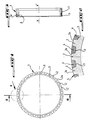
- Figure 1 is an external plan view of a ring gear according to this invention.
- Figure 2 is an enlarged sectional view of the arrowed part II in Figure 1, of this crown.
- Figure 3 is a sectional view along line III-III of Figure 1.
- a ring gear sometimes called a phonic wheel, made for example of steel, which can be fitted to a vehicle wheel (not shown), and comprising a peripheral external toothing 1.
- the teeth 2 of the toothing 1 define between them recesses 3 which are filled with a non-magnetic material forming with the vertices 2a of the teeth 2 a cylindrical peripheral surface S, as can be seen in FIG. 2 .
- Such a cylindrical peripheral surface S can be obtained by machining the crown after filling the recesses 3 receiving the non-magnetic material forming a plurality of elements 4 housed in said recesses between the teeth 2.
- the recesses 3 are preferably filled with a plastic material, such as resin for example, which can be overmolded on the teeth 1 of the crown.
- the elements 4 of plastic material form extensions, parallel to the axis XX ′ of the crown, to a ring 5, also of plastic material surrounding said crown.
- the connection of the plastic elements 4 to the ring 5 makes it possible to obtain good cohesion between the different plastic elements 4.
- the ring 5 is housed or molded into a recess or a groove 6 juxtaposed to the teeth 1 in the axial direction. So, as always seen in Figure 3, the peripheral surface 5a of the ring 5 is located in the extension of the peripheral cylindrical surface of the teeth 1 to hollow 3 filled with plastic.
- the crown After overmolding of the plastic material on the peripheral surface of the steel crown, and which fills the recesses 3 as well as the recess 6, the crown can be machined, as mentioned above, so as to present a perfect cylindrical external surface, well that such machining is not compulsory, the crown, in this case, leaving the mold directly to the dimension.
- a very compact improved toothed crown has therefore been produced according to the invention, which can be manufactured from current steel crowns, having no visible tooth and making it possible to ensure the non-deterioration of the magnetic sensor with which it is associated.
Landscapes
- Physics & Mathematics (AREA)
- General Physics & Mathematics (AREA)
- Transmission And Conversion Of Sensor Element Output (AREA)
- Gears, Cams (AREA)
Claims (2)
- Zahnkranz für einen magnetischen Messwertgeber, der insbesondere bestimmt ist, die Drehgeschwindigkeit eines Fahrzeugrades, dem ein blockierungsverhütendes System zugeordnet ist, zu ermitteln und derjenigen Gattung, die durch einen Kranz, der das besagte Rad ausrüsten kann, gebildet wird, und eine äussere Umfangsverzahnung (1) aufweist, wobei die Lücken (3) zwischen den Zähnen (2) des Kranzes mit Elementen (4) aus nichtmagnetischem Kunststoff ausgefüllt sind, die zur Achse (X-X') des Kranzes parallele Ausdehnungen bilden, mit einem Ring (5) aus nichtmagnetischem Kunststoff, dadurch gekennzeichnet, dass der den Kranz, der metallisch ist, umgebende Ring (5) aus nichtmagnetischem Kunsstoff und der mit seinen Ausdehnungen und mit den Spitzen (2a) der Zähne (2) des Kranzes eine zylindrische Umfangsfläche (S) bildet, in einem Absatz (6) des besagten Kranzes untergebracht ist, welcher Absatz an die Verzahnung (1) des Kranzes in der Axialrichtung angrenzt.
- Mit einem Kranz gemäss Anspruch 1 ausgerüstetes Fahrzeugrad.
Applications Claiming Priority (2)
| Application Number | Priority Date | Filing Date | Title |
|---|---|---|---|
| FR9116048A FR2685484B1 (fr) | 1991-12-23 | 1991-12-23 | Couronne dentee pour capteur magnetique de vitesse et roue de vehicule equipee de cette couronne. |
| FR9116048 | 1991-12-23 |
Publications (2)
| Publication Number | Publication Date |
|---|---|
| EP0549452A1 EP0549452A1 (de) | 1993-06-30 |
| EP0549452B1 true EP0549452B1 (de) | 1996-05-22 |
Family
ID=9420417
Family Applications (1)
| Application Number | Title | Priority Date | Filing Date |
|---|---|---|---|
| EP19920403506 Expired - Lifetime EP0549452B1 (de) | 1991-12-23 | 1992-12-21 | Zahnrad für einen magnetischen Radgeschwindigkeitsmesssensor |
Country Status (3)
| Country | Link |
|---|---|
| EP (1) | EP0549452B1 (de) |
| DE (1) | DE69210976T2 (de) |
| FR (1) | FR2685484B1 (de) |
Families Citing this family (4)
| Publication number | Priority date | Publication date | Assignee | Title |
|---|---|---|---|---|
| WO2009126126A1 (en) | 2008-04-10 | 2009-10-15 | Deere & Company | Motor shaft speed sensor arrangement |
| US9952248B2 (en) * | 2015-10-14 | 2018-04-24 | Danfoss Power Solutions G.m.b.H. & Co. OHG | Speed sensor ring |
| FR3065267A1 (fr) * | 2017-04-18 | 2018-10-19 | Airbus Helicopters | Roue dentee d'un engrenage, dispositif d'engrenage, boite de transmission de puissance et aeronef ayant une voilure tournante |
| US10837510B2 (en) * | 2018-04-10 | 2020-11-17 | Bendix Spicer Foundation Brake Llc | Thermally isolated composite exciter ring |
Family Cites Families (5)
| Publication number | Priority date | Publication date | Assignee | Title |
|---|---|---|---|---|
| US4161120A (en) * | 1978-05-08 | 1979-07-17 | Wabco Westinghouse | Equipment for the detection of rotation parameters in particular for a wheel-velocity sensor |
| JPS6225267A (ja) * | 1985-07-26 | 1987-02-03 | Honda Motor Co Ltd | 磁気信号発生リング |
| DE3735070A1 (de) * | 1987-10-16 | 1989-04-27 | Kugelfischer G Schaefer & Co | Waelzlager mit impulsring zur drehzahlmessung |
| CA1333964C (en) * | 1988-08-24 | 1995-01-17 | David E. Peck | Unitary rotational speed sensor |
| IT1233900B (it) * | 1989-09-28 | 1992-04-21 | Riv Officine Di Villar Perosa | Ruota fonica per il rilevamento della velocita' di un organo rotante, rivestita di materiale elastomerico |
-
1991
- 1991-12-23 FR FR9116048A patent/FR2685484B1/fr not_active Expired - Fee Related
-
1992
- 1992-12-21 EP EP19920403506 patent/EP0549452B1/de not_active Expired - Lifetime
- 1992-12-21 DE DE1992610976 patent/DE69210976T2/de not_active Expired - Fee Related
Also Published As
| Publication number | Publication date |
|---|---|
| EP0549452A1 (de) | 1993-06-30 |
| FR2685484B1 (fr) | 1995-09-08 |
| FR2685484A1 (fr) | 1993-06-25 |
| DE69210976D1 (de) | 1996-06-27 |
| DE69210976T2 (de) | 1997-01-30 |
Similar Documents
| Publication | Publication Date | Title |
|---|---|---|
| FR2570143A1 (fr) | Palier avec pulseur pour roue de vehicule | |
| FR2715011A1 (fr) | Système d'entraînement en rotation de deux organes mécaniques par accouplement magnétique et compteur de fluide comportant un tel système. | |
| EP0745778B1 (de) | Lager mit integrierter Geschwindigkeitsmessvorrichtung | |
| FR2459920A1 (fr) | Galet d'enroulement de chaine, notamment pour les changements de vitesse de bicyclettes et vehicules similaires | |
| EP0057348B1 (de) | Schrägwälzlager mit zwei Reihen Wälzkörper und Verfahren zum Zusammenbau | |
| LU84106A1 (fr) | Vanne-papillon a corps revetu | |
| FR2539197A1 (fr) | Frein a disque | |
| FR2614966A1 (fr) | Organe d'etancheite perfectionne, utilisable notamment pour un palier a roulements, et dispositif permettant de detecter la vitesse d'un organe rotatif moyennant l'utilisation de cet organe d'etancheite | |
| EP0549452A1 (de) | Zahnrad für einen magnetischen Radgeschwindigkeitsmesssensor | |
| EP0149935A2 (de) | Vorrichtung zur abnehmbaren Befestigung einer Zierblende auf einem Fahrzeugrad und Montage mit Hilfe dieser Vorrichtung | |
| WO1999000259A1 (fr) | Jante pour roue de bicyclette | |
| FR2469624A1 (fr) | Changement de vitesse a chaine | |
| FR2614955A1 (fr) | Palier pour supporter un organe en rotation, en particulier pour une roue d'un vehicule et son procede de fabrication | |
| EP0914616B1 (de) | Radnabe mit wälzlager mit einer dichtung mit integriertem kodierer | |
| FR2520693A1 (fr) | Guide-chaine a galets pour les changements de vitesse arriere des cycles et vehicules similaires | |
| EP0174229B1 (de) | Bremskraftverstärker mit Anschlagelement für den Ventilsteuerkolben | |
| FR2729443A1 (fr) | Soufflet de protection | |
| FR2597970A1 (fr) | Capteur a potentiometre rotatif pour le reperage de la position ou du deplacement angulaire d'un arbre tournant | |
| EP0475809B1 (de) | Geschwindigkeitsmessaufnehmer eines drehbaren Elements, insbesondere für ein Kraftfahrzeugrad | |
| FR2658908A1 (fr) | Codeur annulaire composite et procede de fabrication de celui-ci. | |
| FR2474620A3 (fr) | Unite de support pour supporter elastiquement un arbre rotatif | |
| EP0694714B1 (de) | Entkoppelter Schalthebelmechanismus mit einteiligem Schalthebelarm | |
| WO2020109571A1 (fr) | Valve de gonflage à déformation élastique avec une tubulure de corps de valve non-axisymétrique | |
| FR2684713A1 (fr) | Clee dentee, notamment pour serrure ou antivol de vehicule automobile. | |
| FR2723201A1 (fr) | Perfectionnement aux capteurs de grandeur physiqueet electrique, notamment aux capteurs de roulement |
Legal Events
| Date | Code | Title | Description |
|---|---|---|---|
| PUAI | Public reference made under article 153(3) epc to a published international application that has entered the european phase |
Free format text: ORIGINAL CODE: 0009012 |
|
| AK | Designated contracting states |
Kind code of ref document: A1 Designated state(s): DE GB IT |
|
| 17P | Request for examination filed |
Effective date: 19931228 |
|
| 17Q | First examination report despatched |
Effective date: 19950207 |
|
| GRAH | Despatch of communication of intention to grant a patent |
Free format text: ORIGINAL CODE: EPIDOS IGRA |
|
| GRAA | (expected) grant |
Free format text: ORIGINAL CODE: 0009210 |
|
| AK | Designated contracting states |
Kind code of ref document: B1 Designated state(s): DE GB IT |
|
| REF | Corresponds to: |
Ref document number: 69210976 Country of ref document: DE Date of ref document: 19960627 |
|
| ITF | It: translation for a ep patent filed | ||
| GBT | Gb: translation of ep patent filed (gb section 77(6)(a)/1977) |
Effective date: 19960816 |
|
| PLBE | No opposition filed within time limit |
Free format text: ORIGINAL CODE: 0009261 |
|
| 26N | No opposition filed | ||
| REG | Reference to a national code |
Ref country code: GB Ref legal event code: IF02 |
|
| PGFP | Annual fee paid to national office [announced via postgrant information from national office to epo] |
Ref country code: DE Payment date: 20061124 Year of fee payment: 15 |
|
| PGFP | Annual fee paid to national office [announced via postgrant information from national office to epo] |
Ref country code: GB Payment date: 20061127 Year of fee payment: 15 |
|
| PGFP | Annual fee paid to national office [announced via postgrant information from national office to epo] |
Ref country code: IT Payment date: 20061231 Year of fee payment: 15 |
|
| REG | Reference to a national code |
Ref country code: GB Ref legal event code: 746 Effective date: 20070115 |
|
| GBPC | Gb: european patent ceased through non-payment of renewal fee |
Effective date: 20071221 |
|
| PG25 | Lapsed in a contracting state [announced via postgrant information from national office to epo] |
Ref country code: DE Free format text: LAPSE BECAUSE OF NON-PAYMENT OF DUE FEES Effective date: 20080701 |
|
| PG25 | Lapsed in a contracting state [announced via postgrant information from national office to epo] |
Ref country code: GB Free format text: LAPSE BECAUSE OF NON-PAYMENT OF DUE FEES Effective date: 20071221 |
|
| PG25 | Lapsed in a contracting state [announced via postgrant information from national office to epo] |
Ref country code: IT Free format text: LAPSE BECAUSE OF NON-PAYMENT OF DUE FEES Effective date: 20071221 |