EP0549572A1 - Senkrechte Brennkraftmaschine mit im Zylinderkopf liegenden Ventilen - Google Patents
Senkrechte Brennkraftmaschine mit im Zylinderkopf liegenden Ventilen Download PDFInfo
- Publication number
- EP0549572A1 EP0549572A1 EP93200302A EP93200302A EP0549572A1 EP 0549572 A1 EP0549572 A1 EP 0549572A1 EP 93200302 A EP93200302 A EP 93200302A EP 93200302 A EP93200302 A EP 93200302A EP 0549572 A1 EP0549572 A1 EP 0549572A1
- Authority
- EP
- European Patent Office
- Prior art keywords
- combustion engine
- internal combustion
- exhaust
- carburettor
- cylinder
- Prior art date
- Legal status (The legal status is an assumption and is not a legal conclusion. Google has not performed a legal analysis and makes no representation as to the accuracy of the status listed.)
- Granted
Links
Images




Classifications
-
- F—MECHANICAL ENGINEERING; LIGHTING; HEATING; WEAPONS; BLASTING
- F02—COMBUSTION ENGINES; HOT-GAS OR COMBUSTION-PRODUCT ENGINE PLANTS
- F02F—CYLINDERS, PISTONS OR CASINGS, FOR COMBUSTION ENGINES; ARRANGEMENTS OF SEALINGS IN COMBUSTION ENGINES
- F02F1/00—Cylinders; Cylinder heads
- F02F1/24—Cylinder heads
- F02F1/26—Cylinder heads having cooling means
- F02F1/28—Cylinder heads having cooling means for air cooling
- F02F1/30—Finned cylinder heads
- F02F1/32—Finned cylinder heads the cylinder heads being of overhead valve type
-
- F—MECHANICAL ENGINEERING; LIGHTING; HEATING; WEAPONS; BLASTING
- F02—COMBUSTION ENGINES; HOT-GAS OR COMBUSTION-PRODUCT ENGINE PLANTS
- F02B—INTERNAL-COMBUSTION PISTON ENGINES; COMBUSTION ENGINES IN GENERAL
- F02B75/00—Other engines
- F02B75/007—Other engines having vertical crankshafts
-
- F—MECHANICAL ENGINEERING; LIGHTING; HEATING; WEAPONS; BLASTING
- F02—COMBUSTION ENGINES; HOT-GAS OR COMBUSTION-PRODUCT ENGINE PLANTS
- F02B—INTERNAL-COMBUSTION PISTON ENGINES; COMBUSTION ENGINES IN GENERAL
- F02B75/00—Other engines
- F02B75/16—Engines characterised by number of cylinders, e.g. single-cylinder engines
-
- F—MECHANICAL ENGINEERING; LIGHTING; HEATING; WEAPONS; BLASTING
- F02—COMBUSTION ENGINES; HOT-GAS OR COMBUSTION-PRODUCT ENGINE PLANTS
- F02B—INTERNAL-COMBUSTION PISTON ENGINES; COMBUSTION ENGINES IN GENERAL
- F02B1/00—Engines characterised by fuel-air mixture compression
- F02B1/02—Engines characterised by fuel-air mixture compression with positive ignition
- F02B1/04—Engines characterised by fuel-air mixture compression with positive ignition with fuel-air mixture admission into cylinder
-
- F—MECHANICAL ENGINEERING; LIGHTING; HEATING; WEAPONS; BLASTING
- F02—COMBUSTION ENGINES; HOT-GAS OR COMBUSTION-PRODUCT ENGINE PLANTS
- F02B—INTERNAL-COMBUSTION PISTON ENGINES; COMBUSTION ENGINES IN GENERAL
- F02B75/00—Other engines
- F02B75/02—Engines characterised by their cycles, e.g. six-stroke
- F02B2075/022—Engines characterised by their cycles, e.g. six-stroke having less than six strokes per cycle
- F02B2075/027—Engines characterised by their cycles, e.g. six-stroke having less than six strokes per cycle four
-
- F—MECHANICAL ENGINEERING; LIGHTING; HEATING; WEAPONS; BLASTING
- F02—COMBUSTION ENGINES; HOT-GAS OR COMBUSTION-PRODUCT ENGINE PLANTS
- F02B—INTERNAL-COMBUSTION PISTON ENGINES; COMBUSTION ENGINES IN GENERAL
- F02B2275/00—Other engines, components or details, not provided for in other groups of this subclass
- F02B2275/34—Lateral camshaft position
-
- F—MECHANICAL ENGINEERING; LIGHTING; HEATING; WEAPONS; BLASTING
- F02—COMBUSTION ENGINES; HOT-GAS OR COMBUSTION-PRODUCT ENGINE PLANTS
- F02F—CYLINDERS, PISTONS OR CASINGS, FOR COMBUSTION ENGINES; ARRANGEMENTS OF SEALINGS IN COMBUSTION ENGINES
- F02F7/00—Casings, e.g. crankcases
- F02F7/006—Camshaft or pushrod housings
-
- Y—GENERAL TAGGING OF NEW TECHNOLOGICAL DEVELOPMENTS; GENERAL TAGGING OF CROSS-SECTIONAL TECHNOLOGIES SPANNING OVER SEVERAL SECTIONS OF THE IPC; TECHNICAL SUBJECTS COVERED BY FORMER USPC CROSS-REFERENCE ART COLLECTIONS [XRACs] AND DIGESTS
- Y02—TECHNOLOGIES OR APPLICATIONS FOR MITIGATION OR ADAPTATION AGAINST CLIMATE CHANGE
- Y02T—CLIMATE CHANGE MITIGATION TECHNOLOGIES RELATED TO TRANSPORTATION
- Y02T10/00—Road transport of goods or passengers
- Y02T10/10—Internal combustion engine [ICE] based vehicles
- Y02T10/12—Improving ICE efficiencies
Definitions
- the present invention relates to a vertical internal combustion engine having overhead valves, whose crankshaft is arranged vertically.
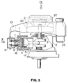
- FIG. 5 One example of a conventional internal vertical combustion engine having overhead valves (FR-A-2 534 626) is illustrated in Figs. 5 to 7 of the accompanying drawings.
- Reference numeral 1 denotes a cylinder block comprising a cylinder barrel 1A, whose centre line is level, a cylinder head 1B and a cylinder head cover 1C, and 2 denotes a crankcase connected with cylinder barrel 1A of cylinder block 1.
- a crankshaft 4 is supported vertically in the centre of the crankcase 2 by bearings 3
- 5 denotes a piston
- 6 denotes a connecting rod.
- a suction valve 7 and exhaust valve 8 are arranged as overhead valves.
- the suction valve 7 and exhaust valve 8 are part of a valve mechanism which includes a camshaft 9 (shown in Fig.6) rotating synchronously with crankshaft 4, a pair of push rods 107 and 108 in upper and lower parts of the cylinder head, which are caused to reciprocate in a straight line by the rotation of the camshaft 9, a pair of rocker arms 117 and 118 which are caused to move up and down by the actuation of said push rods 107 and 108, and a return spring 127 associated with each valve 7 and 8.
- a suction port 137 opens on the right-hand side of cylinder head 1B, and an exhaust port 138 opens on the left-hand side. That is, suction port 137 and exhaust port 138 open such that suction and exhaust gases may flow crosswise.
- the suction valve 7 and exhaust valve 8 are arranged parallel to each other in the same vertical plane, with suction valve 7 in the higher position. As shown in Fig.7, suction port 137 lies between push rod 107 for the suction valve and push rod 108 for the exhaust valve, and it slopes up to suction valve 7 along an imaginary straight line.
- the bottom of the opening of suction port 137 is lower in position than the top of the opening of exhaust port 138 (see Fig.7).
- the location at which a carburettor 14 is connected with the opening of suction port 137 is at the same height as the location at which an exhaust muffler 16 is connected with the opening of exhaust port 138.
- Carburettor 14 is connected directly with the opening of the suction port 137, an air cleaner 15 is connected with said carburettor 14, and exhaust muffler 16 is connected with the opening of exhaust port 138.
- Reference number 17 denotes an elbow connecting carburettor 14 with air cleaner 15, and 18 is an air cleaner element.
- a baffle cover 19 is placed over the cylinder block 1 and crankcase 2, wherein crankshaft 4, flywheel 20 and fan 21 are arranged.
- Numeral 22 is a recoil starter, and 23 is a fuel tank. Spark plug 24 and starter motor 25 are arranged on the same side of the block as exhaust muffler 16.
- a vertical internal combustion engine having overhead valves, a vertically disposed crankshaft and a horizontally disposed cylinder, and comprising: a carburettor arranged on one side of said cylinder and an exhaust muffler arranged on the other side of said cylinder, opposite the carburettor; characterised in that a suction port is coupled to said carburettor and has a horizontal straight portion and a curved portion leading to a suction valve; and in that the central axis of the horizontal straight portion and the central axis of the carburettor are aligned substantially on the same straight line in the same horizontal plane, said curved portion leading smoothly from the end of said horizontal straight portion up to said suction valve.
- reference 51 denotes a cylinder block comprising a cylinder barrel 51a, a cylinder head 51b, and a cylinder-head cover 51c. Centre line 51d of cylinder barrel 51a is horizontal.
- Reference 52 is a suction (inlet) valve and 53 is an exhaust valve, both of which are arranged as a pair of overhead valves in upper and lower parts of cylinder head 51b.
- a pair of push rods 54 and 55 are arranged in the upper and lower parts of the cylinder head, and are caused to reciprocate when a camshaft rotates synchronously with a crankshaft (not shown in any figure).
- Reference 58 is a suction port and, as viewed in Fig.4, it opens on the right-hand side of the cylinder head 51b.
- the suction port 58 is formed with a horizontal, straight portion 59 and a curved portion 60. Curved portion 60 is connected with suction valve 52 and horizontal, straight portion 59 is connected with carburettor 62.
- Reference 70 is an opening in the cylinder head for pushing cooling air in the direction of an output shaft (both upward and downward). The opening 70 is surrounded by the cylinder head wall on the crankcase side of the horizontal straight portion 59, the wall defining the end of the cylinder and the circumferential walls of the openings for the push rods.
- Reference 61 is an exhaust port whose centre line 61a extends through exhaust valve 53 and crosses horizontal straight portion 59 of suction port 58 diagonally from below. In Fig.4, exhaust port 61 is tilted at an angle ⁇ of 5 o to 45 o between centre line 61a and the vertical centre line 100 of the crankshaft.
- the suction valve 52 and the exhaust valve 53 are arranged parallel to each other in the same vertical plane, with suction valve 52 in the higher position.
- the horizontal straight portion 59 extends between push rod 54 for the suction valve and push rod 55 for the exhaust valve.
- Reference 62 denotes a carburettor.
- the shaft centre 62a of the carburettor is aligned on the same straight line in the same horizontal plane as the central axis 59a of horizontal portion 59 of suction port 58.
- carburettor 62 is fixed to cylinder head 51b by screwing a bolt 63 into a tapped hole 64 arranged in a hole (for preventing castings) of cylinder head 51b.
- Reference 65 is an exhaust muffler comprising a right-hand body 65a and a left-hand body 65b, the right-hand body 65a being fixed over the left-hand body 65b. Muffler 65 is installed by fixing a nut 67 around bolt 66 in exhaust port 61. Reference 65c is a part formed on the left-hand body 65b for enabling fixing. Reference 68 is an ignition plug screwed into a tapped hole 69 of cylinder head 51b.
- an air-fuel mixture produced in carburettor 62 passes along horizontal straight portion 59 and up curved portion 60 in the suction port 58, and the suction valve 52 opens, guiding the mixture into the cylinder.
- the air-fuel mixture cools down exhaust gas, because the curved portion 60 is close to the exhaust port 61.
- the curved portion 60 causes the air-fuel mixture to slew around and guides it into the cylinder.
- the muffler may be arranged over the lower part and the side of cylinder block 51, as shown in Fig.2, thereby enabling the enlargement of the capacity of the muffler and improving the muffling effect.
- cooling air coming from a cooling fan flows in the direction of arrow A inside baffle plate 71, cooling down the ignition plug 68 fixed in tapped hole 69, cylinder head 51b, etc.
- cooling air coming from a cooling fan flows in the direction of arrow A inside baffle plate 71, cooling down the ignition plug 68 fixed in tapped hole 69, cylinder head 51b, etc.
- the combustion chamber around ignition plug 68 may be sufficiently cooled down.
- the cooling air cools sufficiently the valve guide of the exhaust valve 53, whereby the exhaust valve 53 and its valve guide may be prevented from seizure.
- the first embodiment of the present invention includes the above-described elements and produces the following effects.
Landscapes
- Engineering & Computer Science (AREA)
- Chemical & Material Sciences (AREA)
- Combustion & Propulsion (AREA)
- Mechanical Engineering (AREA)
- General Engineering & Computer Science (AREA)
- Cylinder Crankcases Of Internal Combustion Engines (AREA)
- Valve-Gear Or Valve Arrangements (AREA)
- Valve Device For Special Equipments (AREA)
- Display Devices Of Pinball Game Machines (AREA)
Applications Claiming Priority (5)
| Application Number | Priority Date | Filing Date | Title |
|---|---|---|---|
| JP41522/90 | 1990-02-22 | ||
| JP4152290A JP2647528B2 (ja) | 1990-02-22 | 1990-02-22 | 縦型頭上弁式内燃機関 |
| JP30493/90 | 1990-03-27 | ||
| JP1990030493U JP2503134Y2 (ja) | 1990-03-27 | 1990-03-27 | 縦型頭上弁式内燃機関 |
| EP90314384A EP0443273B1 (de) | 1990-02-22 | 1990-12-28 | Vertikale Brennkraftmaschine mit hängenden Ventilen |
Related Parent Applications (1)
| Application Number | Title | Priority Date | Filing Date |
|---|---|---|---|
| EP90314384.0 Division | 1990-12-28 |
Publications (2)
| Publication Number | Publication Date |
|---|---|
| EP0549572A1 true EP0549572A1 (de) | 1993-06-30 |
| EP0549572B1 EP0549572B1 (de) | 1995-11-15 |
Family
ID=26368855
Family Applications (3)
| Application Number | Title | Priority Date | Filing Date |
|---|---|---|---|
| EP93200302A Expired - Lifetime EP0549572B1 (de) | 1990-02-22 | 1990-12-28 | Senkrechte Brennkraftmaschine mit im Zylinderkopf liegenden Ventilen |
| EP90314384A Expired - Lifetime EP0443273B1 (de) | 1990-02-22 | 1990-12-28 | Vertikale Brennkraftmaschine mit hängenden Ventilen |
| EP93200300A Expired - Lifetime EP0549571B1 (de) | 1990-02-22 | 1990-12-28 | Senkrechte Brennkraftmaschine mit im Zylinderkopf liegenden Ventilen |
Family Applications After (2)
| Application Number | Title | Priority Date | Filing Date |
|---|---|---|---|
| EP90314384A Expired - Lifetime EP0443273B1 (de) | 1990-02-22 | 1990-12-28 | Vertikale Brennkraftmaschine mit hängenden Ventilen |
| EP93200300A Expired - Lifetime EP0549571B1 (de) | 1990-02-22 | 1990-12-28 | Senkrechte Brennkraftmaschine mit im Zylinderkopf liegenden Ventilen |
Country Status (6)
| Country | Link |
|---|---|
| US (1) | US5159909A (de) |
| EP (3) | EP0549572B1 (de) |
| AT (2) | ATE128206T1 (de) |
| AU (2) | AU635093B2 (de) |
| CA (1) | CA2030583C (de) |
| DE (3) | DE69006715T2 (de) |
Families Citing this family (2)
| Publication number | Priority date | Publication date | Assignee | Title |
|---|---|---|---|---|
| US5335634A (en) * | 1991-05-14 | 1994-08-09 | Mazda Motor Corporation | Combustion chamber structure for an engine |
| RU2146010C1 (ru) * | 1997-12-03 | 2000-02-27 | Грабовский Александр Андреевич | Двигатель внутреннего сгорания |
Citations (2)
| Publication number | Priority date | Publication date | Assignee | Title |
|---|---|---|---|---|
| FR2534626A1 (fr) * | 1982-10-15 | 1984-04-20 | Honda Motor Co Ltd | Moteur a combustion interne tous usages equipe d'un vilebrequin vertical |
| US4864981A (en) * | 1988-07-08 | 1989-09-12 | Kawasaki Jukogyo Kabushiki Kaisha | Overhead valve type engine |
Family Cites Families (5)
| Publication number | Priority date | Publication date | Assignee | Title |
|---|---|---|---|---|
| US4381743A (en) * | 1981-02-26 | 1983-05-03 | General Motors Corporation | Variable area swirl generating engine cylinder inlet port |
| US4693215A (en) * | 1982-09-18 | 1987-09-15 | Kabushiki Kaisha Toyota Chuo Kenkyusho | Inlet port for internal combustion engine |
| US5000126A (en) * | 1986-10-01 | 1991-03-19 | Yamaha Kogyo Hatsudoki Kabushiki Kaisha | Vertical engine for walk-behind lawn mower |
| US4790273A (en) * | 1987-02-19 | 1988-12-13 | Kiyohiko Oguri | Vertical engine for walk behind lawn mower |
| US4893597A (en) * | 1989-04-24 | 1990-01-16 | Tecumseh Products Company | Engine cylinder assembly having an intake cross-passageway |
-
1990
- 1990-11-23 CA CA002030583A patent/CA2030583C/en not_active Expired - Fee Related
- 1990-11-30 US US07/621,019 patent/US5159909A/en not_active Expired - Fee Related
- 1990-11-30 AU AU67662/90A patent/AU635093B2/en not_active Ceased
- 1990-12-28 AT AT93200300T patent/ATE128206T1/de not_active IP Right Cessation
- 1990-12-28 EP EP93200302A patent/EP0549572B1/de not_active Expired - Lifetime
- 1990-12-28 DE DE69006715T patent/DE69006715T2/de not_active Expired - Fee Related
- 1990-12-28 EP EP90314384A patent/EP0443273B1/de not_active Expired - Lifetime
- 1990-12-28 EP EP93200300A patent/EP0549571B1/de not_active Expired - Lifetime
- 1990-12-28 DE DE69022603T patent/DE69022603T2/de not_active Expired - Fee Related
- 1990-12-28 AT AT93200302T patent/ATE130400T1/de not_active IP Right Cessation
- 1990-12-28 DE DE69023671T patent/DE69023671T2/de not_active Expired - Fee Related
-
1992
- 1992-10-09 AU AU26309/92A patent/AU648202B2/en not_active Ceased
Patent Citations (2)
| Publication number | Priority date | Publication date | Assignee | Title |
|---|---|---|---|---|
| FR2534626A1 (fr) * | 1982-10-15 | 1984-04-20 | Honda Motor Co Ltd | Moteur a combustion interne tous usages equipe d'un vilebrequin vertical |
| US4864981A (en) * | 1988-07-08 | 1989-09-12 | Kawasaki Jukogyo Kabushiki Kaisha | Overhead valve type engine |
Also Published As
| Publication number | Publication date |
|---|---|
| DE69022603T2 (de) | 1996-04-18 |
| EP0443273B1 (de) | 1994-02-16 |
| EP0549571B1 (de) | 1995-09-20 |
| CA2030583A1 (en) | 1991-08-23 |
| DE69023671T2 (de) | 1996-05-02 |
| EP0549571A1 (de) | 1993-06-30 |
| DE69023671D1 (de) | 1995-12-21 |
| DE69006715T2 (de) | 1994-05-26 |
| AU648202B2 (en) | 1994-04-14 |
| EP0443273A1 (de) | 1991-08-28 |
| CA2030583C (en) | 1998-06-02 |
| DE69022603D1 (de) | 1995-10-26 |
| AU635093B2 (en) | 1993-03-11 |
| ATE128206T1 (de) | 1995-10-15 |
| AU2630992A (en) | 1992-12-03 |
| DE69006715D1 (de) | 1994-03-24 |
| ATE130400T1 (de) | 1995-12-15 |
| AU6766290A (en) | 1991-08-29 |
| US5159909A (en) | 1992-11-03 |
| EP0549572B1 (de) | 1995-11-15 |
Similar Documents
| Publication | Publication Date | Title |
|---|---|---|
| US4570584A (en) | General-purpose internal combustion engine with vertical crank shaft | |
| US7559299B2 (en) | Monolithic cylinder-crankcase | |
| US7201132B2 (en) | Combustion engine of vertical shaft type | |
| WO2000043660A1 (en) | Cylinder for internal combustion engine | |
| US5161490A (en) | Air-cooled internal combustion engine | |
| JPH07197865A (ja) | V型多気筒エンジンの吸気装置 | |
| EP0443273B1 (de) | Vertikale Brennkraftmaschine mit hängenden Ventilen | |
| US5243936A (en) | Vertical internal combustion engine with overhead valves | |
| US4864981A (en) | Overhead valve type engine | |
| JPH08151917A (ja) | ブリーザ装置付きエンジン | |
| US3709200A (en) | Cooling water conduit system in internal combustion engines | |
| US7572159B2 (en) | Internal combustion engine installed in engine compartment | |
| JP2647528B2 (ja) | 縦型頭上弁式内燃機関 | |
| US6168484B1 (en) | Intake apparatus of outboard motor | |
| EP3839222A1 (de) | Motor mit lüftung | |
| US4893597A (en) | Engine cylinder assembly having an intake cross-passageway | |
| GB2296292A (en) | Spark-ignition i.c.engine | |
| JP2503134Y2 (ja) | 縦型頭上弁式内燃機関 | |
| KR960010278B1 (ko) | 디이젤엔진의 실린더 헤드 | |
| CA1306152C (en) | Overhead valve type engine | |
| US6161509A (en) | Cylinder | |
| US6305340B1 (en) | Slanted internal combustion engine | |
| JPH0339185B2 (de) | ||
| JPH1026022A (ja) | 空冷式内燃機関の排気系構造 | |
| JPH0893437A (ja) | 内燃機関のロッカカバー装置 |
Legal Events
| Date | Code | Title | Description |
|---|---|---|---|
| PUAI | Public reference made under article 153(3) epc to a published international application that has entered the european phase |
Free format text: ORIGINAL CODE: 0009012 |
|
| 17P | Request for examination filed |
Effective date: 19930204 |
|
| AC | Divisional application: reference to earlier application |
Ref document number: 443273 Country of ref document: EP |
|
| AK | Designated contracting states |
Kind code of ref document: A1 Designated state(s): AT DE FR GB IT |
|
| 17Q | First examination report despatched |
Effective date: 19940711 |
|
| GRAA | (expected) grant |
Free format text: ORIGINAL CODE: 0009210 |
|
| ITF | It: translation for a ep patent filed | ||
| AC | Divisional application: reference to earlier application |
Ref document number: 443273 Country of ref document: EP |
|
| AK | Designated contracting states |
Kind code of ref document: B1 Designated state(s): AT DE FR GB IT |
|
| REF | Corresponds to: |
Ref document number: 130400 Country of ref document: AT Date of ref document: 19951215 Kind code of ref document: T |
|
| REF | Corresponds to: |
Ref document number: 69023671 Country of ref document: DE Date of ref document: 19951221 |
|
| ET | Fr: translation filed | ||
| PLBE | No opposition filed within time limit |
Free format text: ORIGINAL CODE: 0009261 |
|
| STAA | Information on the status of an ep patent application or granted ep patent |
Free format text: STATUS: NO OPPOSITION FILED WITHIN TIME LIMIT |
|
| 26N | No opposition filed | ||
| PGFP | Annual fee paid to national office [announced via postgrant information from national office to epo] |
Ref country code: FR Payment date: 19961211 Year of fee payment: 7 |
|
| PGFP | Annual fee paid to national office [announced via postgrant information from national office to epo] |
Ref country code: AT Payment date: 19961212 Year of fee payment: 7 |
|
| PGFP | Annual fee paid to national office [announced via postgrant information from national office to epo] |
Ref country code: GB Payment date: 19961219 Year of fee payment: 7 |
|
| PGFP | Annual fee paid to national office [announced via postgrant information from national office to epo] |
Ref country code: DE Payment date: 19970107 Year of fee payment: 7 |
|
| PG25 | Lapsed in a contracting state [announced via postgrant information from national office to epo] |
Ref country code: GB Free format text: LAPSE BECAUSE OF NON-PAYMENT OF DUE FEES Effective date: 19971228 Ref country code: AT Free format text: LAPSE BECAUSE OF NON-PAYMENT OF DUE FEES Effective date: 19971228 |
|
| PG25 | Lapsed in a contracting state [announced via postgrant information from national office to epo] |
Ref country code: FR Free format text: THE PATENT HAS BEEN ANNULLED BY A DECISION OF A NATIONAL AUTHORITY Effective date: 19971231 |
|
| GBPC | Gb: european patent ceased through non-payment of renewal fee |
Effective date: 19971228 |
|
| PG25 | Lapsed in a contracting state [announced via postgrant information from national office to epo] |
Ref country code: DE Free format text: LAPSE BECAUSE OF NON-PAYMENT OF DUE FEES Effective date: 19980901 |
|
| REG | Reference to a national code |
Ref country code: FR Ref legal event code: ST |
|
| PG25 | Lapsed in a contracting state [announced via postgrant information from national office to epo] |
Ref country code: IT Free format text: LAPSE BECAUSE OF NON-PAYMENT OF DUE FEES;WARNING: LAPSES OF ITALIAN PATENTS WITH EFFECTIVE DATE BEFORE 2007 MAY HAVE OCCURRED AT ANY TIME BEFORE 2007. THE CORRECT EFFECTIVE DATE MAY BE DIFFERENT FROM THE ONE RECORDED. Effective date: 20051228 |