EP0549715B1 - Rasoir - Google Patents
Rasoir Download PDFInfo
- Publication number
- EP0549715B1 EP0549715B1 EP91918507A EP91918507A EP0549715B1 EP 0549715 B1 EP0549715 B1 EP 0549715B1 EP 91918507 A EP91918507 A EP 91918507A EP 91918507 A EP91918507 A EP 91918507A EP 0549715 B1 EP0549715 B1 EP 0549715B1
- Authority
- EP
- European Patent Office
- Prior art keywords
- base member
- razor
- blades
- protrusions
- fingers
- Prior art date
- Legal status (The legal status is an assumption and is not a legal conclusion. Google has not performed a legal analysis and makes no representation as to the accuracy of the status listed.)
- Expired - Lifetime
Links
- 239000000463 material Substances 0.000 claims description 4
- 239000013536 elastomeric material Substances 0.000 claims description 2
- 239000002991 molded plastic Substances 0.000 claims 1
- XLYOFNOQVPJJNP-UHFFFAOYSA-N water Substances O XLYOFNOQVPJJNP-UHFFFAOYSA-N 0.000 description 10
- 239000006260 foam Substances 0.000 description 3
- 238000010276 construction Methods 0.000 description 2
- 239000004677 Nylon Substances 0.000 description 1
- 239000004743 Polypropylene Substances 0.000 description 1
- 229910000831 Steel Inorganic materials 0.000 description 1
- 238000010521 absorption reaction Methods 0.000 description 1
- DHKHKXVYLBGOIT-UHFFFAOYSA-N acetaldehyde Diethyl Acetal Natural products CCOC(C)OCC DHKHKXVYLBGOIT-UHFFFAOYSA-N 0.000 description 1
- 125000002777 acetyl group Chemical class [H]C([H])([H])C(*)=O 0.000 description 1
- 238000007599 discharging Methods 0.000 description 1
- 238000001035 drying Methods 0.000 description 1
- 230000002708 enhancing effect Effects 0.000 description 1
- 239000002184 metal Substances 0.000 description 1
- 230000004048 modification Effects 0.000 description 1
- 238000012986 modification Methods 0.000 description 1
- 238000000465 moulding Methods 0.000 description 1
- 229920001778 nylon Polymers 0.000 description 1
- 239000004033 plastic Substances 0.000 description 1
- -1 polypropylene Polymers 0.000 description 1
- 229920001155 polypropylene Polymers 0.000 description 1
- 239000010959 steel Substances 0.000 description 1
Images




Classifications
-
- B—PERFORMING OPERATIONS; TRANSPORTING
- B26—HAND CUTTING TOOLS; CUTTING; SEVERING
- B26B—HAND-HELD CUTTING TOOLS NOT OTHERWISE PROVIDED FOR
- B26B19/00—Clippers or shavers operating with a plurality of cutting edges, e.g. hair clippers, dry shavers
- B26B19/38—Details of, or accessories for, hair clippers, or dry shavers, e.g. housings, casings, grips, guards
- B26B19/384—Dry-shaver foils; Manufacture thereof
-
- B—PERFORMING OPERATIONS; TRANSPORTING
- B26—HAND CUTTING TOOLS; CUTTING; SEVERING
- B26B—HAND-HELD CUTTING TOOLS NOT OTHERWISE PROVIDED FOR
- B26B21/00—Razors of the open or knife type; Safety razors or other shaving implements of the planing type; Hair-trimming devices involving a razor-blade; Equipment therefor
- B26B21/08—Razors of the open or knife type; Safety razors or other shaving implements of the planing type; Hair-trimming devices involving a razor-blade; Equipment therefor involving changeable blades
- B26B21/14—Safety razors with one or more blades arranged transversely to the handle
- B26B21/16—Safety razors with one or more blades arranged transversely to the handle involving blades with only one cutting edge
- B26B21/165—Safety razors with one or more blades arranged transversely to the handle involving blades with only one cutting edge with the blade moulded into, or attached to, a changeable unit
-
- B—PERFORMING OPERATIONS; TRANSPORTING
- B26—HAND CUTTING TOOLS; CUTTING; SEVERING
- B26B—HAND-HELD CUTTING TOOLS NOT OTHERWISE PROVIDED FOR
- B26B21/00—Razors of the open or knife type; Safety razors or other shaving implements of the planing type; Hair-trimming devices involving a razor-blade; Equipment therefor
- B26B21/40—Details or accessories
- B26B21/52—Handles, e.g. tiltable, flexible
Definitions
- This invention relates to wet-shaving razors and is directed more particularly to a razor having means thereon for resiliently supporting blade means.
- One such shaving device is disclosed, for example. in U.S. Patent No. 4 875 288, issued October 24, 1989, in the name of Robert A. Trotta et al.
- This document describes a device which includes a plurality of blades, each blade comprising a tubular wall having an inwardly facing flange formed on one end and an outwardly facing flange formed on the other end.
- the inwardly facing flange of each blade has a sharpened cutting edge thereon.
- the outwardly facing flange of each blade rests upon a resilient foam pad member, or the like, which permits movement of the blades during shaving, to conform to the contour of a surface being shaved.
- a similar shaving device is disclosed in U.S. Patent No. 4 807 360, issued February 28, 1989 in the name of Jeffrey C. Cerier et al.
- the resilient pad member disclosed in the above-mentioned patents provides a resilient mounting for the blade members, it can absorb water during a shaving operation, and become heavy and, when pressure is applied, release undesirable quantities of water.
- a foam pad, of the type disclosed in the above-mentioned patents also is difficult to rinse clean and, after a time, becomes a collection point for shaving debris.
- an object of the present invention to provide a razor having a base member on which are mounted tubular blade means of the type above described, the base member providing a resilient mounting for the blade means, the resilient mounting affording a pre-selected spring force on the blade means.
- a still further object of the invention is to provide such a razor in which the base member is such as not to absorb or collect water therein and is therefore incapable of discharging quantities of water upon application of pressure thereagainst.
- a feature of the present invention is the provision of a razor according to claim 1.
- a further feature of the invention is the provision of a razor blade support for supporting tubular razor blades according to claim 12.
- the illustrative razor further includes a base member 12 attached to and contained within the housing 2.
- An upper surface 11 of a top wall of the base member 12 and the housing top wall 6 are generally parallel to each other (Fig. 6) and spaced from each other.
- Resilient protrusions extend from the upper surface 11 of the base member 12 and comprise spring fingers 14 on which are mounted razor blades 16.
- Rigid protrusions 15 extend from the upper surface 11 of the base member 12, with the spring fingers 14 and the rigid protrusions 15 arranged around holes 17 in the base member surface 11. The holes 17 are aligned with the housing holes 10.
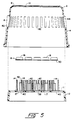
- the base member 12 preferably is formed of a semi-rigid elastomeric material, such as nylon or acetal, impervious to water, and the spring fingers 14 and the rigid protrusions 15 are formed integrally therewith. As may be seen in Figs. 3-5, though formed of the same material, the fingers 14 and the rigid protrusions 15 may be endowed with different resiliency characteristics because of their different configurations.
- the spring fingers 14 are relatively long and slender, compared to the relatively short and broad protrusions 15. Further, as will be described below, many of the protrusions 15 comprise two or three legs, which add to the rigidity of such protrusions.
- Each of the spring fingers 14 includes at least one edge, as the outboard edge 13 shown in Fig. 6, which inclines from a relatively broad base to a narrow, nearly pointed, free upper end.
- Each of the blades 16 has a generally tubular wall 18 defining a central aperture 20 (Fig. 6) therethrough.
- An integrally formed first flange 22 extends inwardly from a first end 24 of the tubular wall 18 and has at a free edge 26 thereof an annular, inwardly-directed, cutting edge 28.
- An integrally formed second flange 30 extends outwardly from a second end 32 of the tubular wall 18. The second flange 30 is adapted to be disposed against an underside 34 of the top wall 6 of the housing 2.
- the blades 16 preferably are of metal, such as treated steel.
- the rigid protrusions 15 are of less height than the spring fingers 14, and are provided with flat surfaces 42 at their free ends.
- the rigid protrusions free end flat surfaces 42 are adapted to receive thereon the second flanges 30 of the blades 16 (Fig. 6).
- the base member top wall holes 17 may be provided in three rows. Referring to Fig. 4, it will be seen that the base member is provided with a first row 50 of the holes 17, the first row of holes being disposed in a line proximate a first side wall 52 of the base member. The base member is further provided with a second row 54 of holes, the second row of holes being disposed in a line proximate a second side wall 56 of the base member. The holes of the second row 54 are aligned with the holes of the first row 50 sidewise of the base member, that is, in a direction from the first side wall 52 to the second side wall 56.
- the base member is provided with a third row 58 of holes between the first and second rows 50,54, the third row of holes being offset from the holes of the first and second rows, such that the holes of the third row are at least in part disposed in paths 60 between the first and second row holes.
- the holes 10 of the top wall 6 of the housing 2 are arranged in a similar fashion, such that each housing hole 10 is aligned with a base member hole 17.
- the blades 16 are mounted on the spring fingers 14, as illustrated in Figs. 5 and 6, and the housing 2 and base member 12 brought together to trap the blades therebetween.
- the housing and base member side walls may simply "snap" together and be locked together by a detent arrangement (not shown).
- the blades 16 rest on the inclined outboard edges 13 of the spring finger 14, with the blades second flanges 30 engaging the underside 34 of the housing top wall 6.
- the spring fingers 14 may be designed to afford a selected spring force on the blades 16 which they support. Knowing the material from which the spring fingers are to be made, the number and location of the spring fingers for each blade, as for example three fingers spaced 120° apart, and the configuration of the spring fingers, the dimensions of the spring fingers may be tailored to permit safe and efficient movement of the blades. Ideally, the blades are spring loaded by the spring fingers 14 to retract into the housing when a normal force on the blades exceeds 5 to 11 grams. The blades are movable reciprocally into the housing 2 and are also movable in a tilting fashion to accommodate to the contours of a surface being shaved.
- the second flanges 30 retain the blades 16 in the holes 10, and the spring fingers 14 provide resilient support for the blades.
- the fingers When pressure is applied to a blade sufficient to overcome the resistance to flexure of the blade's supporting fingers 14, the fingers flex inwardly, permitting the blade to move downwardly in its hole 10. The extent of the blade movement downwardly into the housing 2 is limited by engagement of the blade second flange 30 with the flat surface 42 of the rigid protrusions 15.
- the fingers 14 tend to return to their unstressed state and, because of the inclined edges 13, cause the blade to ride upwardly, back into its more elevated position.
- the razor herein described is well suited for shaving underarms (Figs. 9 and 10) and legs (Figs. 7 and 8).
- the housing 2 the base member 12, and the blades 16 are impervious to water, there is no sponge-like absorption of water and, therefore, no undesirable release of water when the razor is pressed against a shaving surface. Further, the razor herein described is easily rinsed and kept clean and free of shaving debris.
- the alignment of the holes 10 and 17 permits a flow of water from a faucet to pass through the blades 16, the housing 2, and the base member 12, carrying away any debris which may have accumulated interiorly of the housing or the blades.
- the housing may be provided with slots 62 (Fig. 5) between the ribs 8 to provide additional channels for the flow of water through the housing, as well as circulation of air for drying purposes.
Landscapes
- Engineering & Computer Science (AREA)
- Life Sciences & Earth Sciences (AREA)
- Forests & Forestry (AREA)
- Mechanical Engineering (AREA)
- Manufacturing & Machinery (AREA)
- Dry Shavers And Clippers (AREA)
Abstract
Claims (13)
- Rasoir ayant une lame tubulaire (16), un organe de base (12), des doigts élastiques (14) dépassant de l'organe de base (12) et pénétrant dans la lame tubulaire (16), les doigts (14) étant destinés à fléchir vers l'intérieur les uns vers les autres lors de l'application d'une pression contre la lame (16) afin que la lame puisse se déplacer sur les doigts vers l'organe de base.
- Rasoir selon la revendication 1, comportant des saillies rigides (15) de hauteur inférieure à celle des doigts élastiques, dépassant de l'organe de base (12), les saillies ayant des surfaces (42) d'extrémité destinées à être au contact de la lame (16) pour limiter le déplacement de la lame vers l'organe de base (12).
- Rasoir selon la revendication 2, dans lequel les doigts élastiques (14) ont chacun un bord externe (13) incliné d'une extrémité libre vers une partie de base relativement plus large, la lame (16) coopérant avec les bords externes et étant destinée à se déplacer vers les extrémités libres des doigts élastiques (14) sous l'action de la force de rappel des doigts élastiques de manière qu'elle se déplace vers une position sans contrainte.
- Rasoir selon la revendication 3, dans lequel l'organe de base (12) est placé dans un boîtier (2) ayant un trou, la lame tubulaire (16) est disposée dans le trou du boîtier et est mobile par pivotement et en translation sur les doigts élastiques, et l'organe de base a un trou (17) aligné sur le trou du boîtier (10), les doigts élastiques et les saillies rigides étant disposés autour de la périphérie du trou de l'organe de base.
- Rasoir ayant un organe de base (12), des saillies élastiques (14) dépassant de l'organe de base, des lames (16) de rasoir montées sur les saillies élastiques, chacune des lames de rasoir ayant une paroi (18) de forme générale tubulaire délimitant un orifice central et un premier flasque (22) formé afin qu'il en soit solidaire à une première extrémité de la paroi tubulaire, le premier flasque ayant, à un bord libre, un bord de coupe annulaire (28), la saillie élastique pénétrant dans les secondes extrémités des parois tubulaires, si bien que les saillies élastiques Placées dans les parois tubulaires permettent un déplacement des lames sous l'action des pressions appliquées pendant les opérations de rasage.
- Rasoir selon la revendication 7, dans lequel l'organe de base (12) est formé d'un matériau élastomère, et les saillies élastiques (14) sont formées de manière solidaire de l'organe de base et sous forme de prolongements de celui-ci.
- Rasoir selon la revendication 6, ayant un boîtier (2) qui possède une paroi supérieure (6) disposée de façon générale parallèlement à l'organe de base (12) et à distance de celui-ci, la paroi supérieure ayant des trous (10) qui la traversent et les lames étant disposées dans les trous, et les lames comportent chacune un second flasque (30) formé de manière solidaire à sa seconde extrémité, le second flasque dépassant vers l'extérieur de la paroi tubulaire et étant destiné à être en butée contre une face inférieure de la paroi supérieure (6) du boîtier (2).
- Rasoir selon l'une quelconque des revendications 5 à 7, dans lequel le premier flasque (22) est dirigé vers l'intérieur de la paroi tubulaire et le bord de coupe annulaire (28) est dirigé vers l'intérieur.
- Rasoir selon l'une quelconque des revendications 5 à 8, dans lequel des saillies rigides (15) dépassent de l'organe de base (12), les saillies rigides étant proches des doigts élastiques (14) et ayant une hauteur inférieure à celle des doigts élastiques, les saillies rigides ayant des surfaces d'extrémité destinées à coopérer avec les lames (16) afin qu'elles limitent le déplacement des lames vers l'organe de base.
- Rasoir selon la revendication 9, dans lequel chacun des doigts élastiques a un bord externe (13) incliné d'une extrémité libre du doigt élastique vers l'extérieur vers une base relativement plus large du doigt élastique, les lames coopérant avec les bords inclinés des doigts élastiques, les lames étant destinées à se déplacer le long des bords vers les extrémités libres des doigts élastiques lorsque les doigts élastiques fléchissent vers l'extérieur pour reprendre leur position sans contrainte.
- Rasoir selon la revendication 10, ayant un boîtier (2) qui a une paroi supérieure (6) parallèle de façon générale à l'organe de base (12) et distante de celui-ci, la paroi supérieure ayant des trous (10) qui la traversent et les lames (16) sont disposées dans les trous, les lames ayant chacune un second flasque (30) dépassant à l'extérieur de la paroi tubulaire, le second flasque étant destiné à être en butée contre une face inférieure de la paroi supérieure (6) du boîtier afin qu'il limite le déplacement des lames sur les doigts élastiques vers les extrémités libres des doigts élastiques, l'organe de base (12) ayant des trous (17) qui sont alignés sur les trous (10) du boîtier, et les doigts élastiques (14) et les saillies rigides (15) étant disposés sous forme alternée autour des trous de l'organe de base.
- Support de lames de rasoir destiné à supporter des lames tubulaires de rasoir, dans lequel le support comporte un organe de base (12) ayant une paroi supérieure (11) et des parois latérales qui en descendent, la paroi supérieure ayant des trous (17) qui la traversent, et des saillies remontant de la paroi supérieure et placées autour des trous, les saillies comprenant des doigts élastiques (14) et des saillies rigides (15), l'organe de base étant formé de matière plastique moulée et les saillies étant moulées en une seule pièce avec l'organe de base.
- Support de lames de rasoir selon la revendication 12, dans lequel les doigts élastiques (14) et les saillies rigides (15) sont disposés en alternance autour des trous (17).
Applications Claiming Priority (3)
| Application Number | Priority Date | Filing Date | Title |
|---|---|---|---|
| US585258 | 1990-09-19 | ||
| US07/585,258 US5031317A (en) | 1990-09-19 | 1990-09-19 | Razor |
| PCT/US1991/006662 WO1992005017A1 (fr) | 1990-09-19 | 1991-09-16 | Rasoir |
Publications (3)
| Publication Number | Publication Date |
|---|---|
| EP0549715A1 EP0549715A1 (fr) | 1993-07-07 |
| EP0549715A4 EP0549715A4 (en) | 1993-11-10 |
| EP0549715B1 true EP0549715B1 (fr) | 1995-07-19 |
Family
ID=24340690
Family Applications (1)
| Application Number | Title | Priority Date | Filing Date |
|---|---|---|---|
| EP91918507A Expired - Lifetime EP0549715B1 (fr) | 1990-09-19 | 1991-09-16 | Rasoir |
Country Status (10)
| Country | Link |
|---|---|
| US (1) | US5031317A (fr) |
| EP (1) | EP0549715B1 (fr) |
| JP (1) | JPH06502324A (fr) |
| CN (1) | CN1027354C (fr) |
| AU (1) | AU8848691A (fr) |
| CA (1) | CA2090403C (fr) |
| DE (1) | DE69111458T2 (fr) |
| MA (1) | MA22285A1 (fr) |
| MX (1) | MX9101137A (fr) |
| WO (1) | WO1992005017A1 (fr) |
Families Citing this family (11)
| Publication number | Priority date | Publication date | Assignee | Title |
|---|---|---|---|---|
| US5604983A (en) * | 1994-04-14 | 1997-02-25 | The Gillette Company | Razor system |
| US5490329A (en) * | 1994-05-17 | 1996-02-13 | The Gillette Company | Shaving system |
| US6185823B1 (en) * | 1995-11-10 | 2001-02-13 | The Gillette Company | Oval frame razor |
| US6161287A (en) * | 1998-04-24 | 2000-12-19 | The Gillette Company | Razor blade system |
| WO2003095160A1 (fr) * | 2002-05-07 | 2003-11-20 | Eveready Battery Company, Inc. | Recipient pour cartouche de remplacement |
| US7197825B2 (en) | 2004-03-11 | 2007-04-03 | The Gillette Company | Razors and shaving cartridges with guard |
| US20060272460A1 (en) * | 2005-06-02 | 2006-12-07 | Cheng-Jih Li | Shaving razors |
| US9227331B2 (en) | 2012-11-06 | 2016-01-05 | The Gillette Company | Razor blade unit |
| US10850412B2 (en) * | 2018-03-02 | 2020-12-01 | II John Robert Harris | Razor with rotatable head |
| US20220330984A1 (en) * | 2021-04-20 | 2022-10-20 | The Gillette Company Llc | Frame member for use with treatment sheet |
| US20260070245A1 (en) * | 2024-09-06 | 2026-03-12 | The Gillette Company Llc | Shaving apparatus |
Family Cites Families (15)
| Publication number | Priority date | Publication date | Assignee | Title |
|---|---|---|---|---|
| US2632242A (en) * | 1950-01-31 | 1953-03-24 | Musso Ferdinando Pasquale | Safety razor |
| US3702026A (en) * | 1971-10-18 | 1972-11-07 | Unirazor Ltd | Razor |
| US4057896A (en) * | 1975-05-12 | 1977-11-15 | The Gillette Company | Razor handle |
| US4198746A (en) * | 1977-06-09 | 1980-04-22 | The Gillette Company | All plastic swivel head razor handle |
| US4325392A (en) * | 1979-06-04 | 1982-04-20 | American Safety Razor Company | Facial brush for controlling pseudofolliculitis barbae |
| US4378634A (en) * | 1979-12-07 | 1983-04-05 | The Gillette Company | Razor blade assembly |
| US4302876A (en) * | 1980-03-14 | 1981-12-01 | Warner-Lambert Company | Razor blade with inclined edge |
| US4294010A (en) * | 1980-05-23 | 1981-10-13 | Warner-Lambert Company | Rotatable safety razor and blade cartridge therefor |
| US4324041A (en) * | 1980-08-07 | 1982-04-13 | The Gillette Company | Razor blade assembly |
| US4337575A (en) * | 1980-08-07 | 1982-07-06 | The Gillette Company | Razor blade assembly |
| US4574476A (en) * | 1982-09-27 | 1986-03-11 | Warner-Lambert Company | Razor blade assembly |
| MA21155A1 (fr) * | 1987-01-09 | 1988-10-01 | Gillette Co | Rasoirs mecaniques. |
| US4926553A (en) * | 1987-07-17 | 1990-05-22 | Michael Miskin | Razor |
| US4875288A (en) * | 1987-09-02 | 1989-10-24 | The Gillette Company | Shaving device |
| US4807360A (en) * | 1987-09-02 | 1989-02-28 | The Gillette Company | Shaving device |
-
1990
- 1990-09-19 US US07/585,258 patent/US5031317A/en not_active Expired - Fee Related
-
1991
- 1991-09-16 DE DE69111458T patent/DE69111458T2/de not_active Expired - Fee Related
- 1991-09-16 AU AU88486/91A patent/AU8848691A/en not_active Abandoned
- 1991-09-16 CA CA002090403A patent/CA2090403C/fr not_active Expired - Fee Related
- 1991-09-16 WO PCT/US1991/006662 patent/WO1992005017A1/fr not_active Ceased
- 1991-09-16 EP EP91918507A patent/EP0549715B1/fr not_active Expired - Lifetime
- 1991-09-16 JP JP3517872A patent/JPH06502324A/ja active Pending
- 1991-09-18 MA MA22566A patent/MA22285A1/fr unknown
- 1991-09-18 MX MX9101137A patent/MX9101137A/es unknown
- 1991-09-19 CN CN91109021A patent/CN1027354C/zh not_active Expired - Fee Related
Also Published As
| Publication number | Publication date |
|---|---|
| DE69111458D1 (de) | 1995-08-24 |
| WO1992005017A1 (fr) | 1992-04-02 |
| JPH06502324A (ja) | 1994-03-17 |
| CN1060057A (zh) | 1992-04-08 |
| MX9101137A (es) | 1992-05-04 |
| EP0549715A4 (en) | 1993-11-10 |
| CN1027354C (zh) | 1995-01-11 |
| AU8848691A (en) | 1992-04-15 |
| US5031317A (en) | 1991-07-16 |
| DE69111458T2 (de) | 1996-04-04 |
| MA22285A1 (fr) | 1992-04-01 |
| CA2090403C (fr) | 1998-12-08 |
| EP0549715A1 (fr) | 1993-07-07 |
| CA2090403A1 (fr) | 1992-03-20 |
Similar Documents
| Publication | Publication Date | Title |
|---|---|---|
| EP1340600B1 (fr) | Rasoir | |
| EP0549715B1 (fr) | Rasoir | |
| EP0321883B1 (fr) | Unité de rasage à sureté | |
| EP0305883B1 (fr) | Appareil à raser | |
| AU703762B2 (en) | Razor construction | |
| EP1937444B1 (fr) | Éléments de montage de lames pour cartouche de rasoir | |
| EP0305866B1 (fr) | Appareil à raser | |
| EP0197127B1 (fr) | Assemblage de lame de rasoir | |
| EP0198854A4 (fr) | Assemblage de lame de rasoir. | |
| GB2277049A (en) | Movable blade shaving cartridge or the like | |
| AU636463B2 (en) | Shaving system | |
| USRE36816E (en) | Guard for razor blade assembly | |
| HK1058773B (en) | Shaving device | |
| HK1034922B (en) | Razor blade system |
Legal Events
| Date | Code | Title | Description |
|---|---|---|---|
| PUAI | Public reference made under article 153(3) epc to a published international application that has entered the european phase |
Free format text: ORIGINAL CODE: 0009012 |
|
| 17P | Request for examination filed |
Effective date: 19930413 |
|
| AK | Designated contracting states |
Kind code of ref document: A1 Designated state(s): AT BE CH DE DK ES FR GB GR IT LI LU NL SE |
|
| RHK1 | Main classification (correction) |
Ipc: B26B 21/22 |
|
| A4 | Supplementary search report drawn up and despatched |
Effective date: 19930927 |
|
| AK | Designated contracting states |
Kind code of ref document: A4 Designated state(s): AT BE CH DE DK ES FR GB GR IT LI LU NL SE |
|
| RBV | Designated contracting states (corrected) |
Designated state(s): DE FR GB |
|
| 17Q | First examination report despatched |
Effective date: 19940919 |
|
| GRAA | (expected) grant |
Free format text: ORIGINAL CODE: 0009210 |
|
| AK | Designated contracting states |
Kind code of ref document: B1 Designated state(s): DE FR GB |
|
| REF | Corresponds to: |
Ref document number: 69111458 Country of ref document: DE Date of ref document: 19950824 |
|
| ET | Fr: translation filed | ||
| PLBE | No opposition filed within time limit |
Free format text: ORIGINAL CODE: 0009261 |
|
| STAA | Information on the status of an ep patent application or granted ep patent |
Free format text: STATUS: NO OPPOSITION FILED WITHIN TIME LIMIT |
|
| 26N | No opposition filed | ||
| PGFP | Annual fee paid to national office [announced via postgrant information from national office to epo] |
Ref country code: FR Payment date: 20000901 Year of fee payment: 10 |
|
| PGFP | Annual fee paid to national office [announced via postgrant information from national office to epo] |
Ref country code: GB Payment date: 20000905 Year of fee payment: 10 Ref country code: DE Payment date: 20000905 Year of fee payment: 10 |
|
| PG25 | Lapsed in a contracting state [announced via postgrant information from national office to epo] |
Ref country code: GB Free format text: LAPSE BECAUSE OF NON-PAYMENT OF DUE FEES Effective date: 20010916 |
|
| REG | Reference to a national code |
Ref country code: GB Ref legal event code: IF02 |
|
| GBPC | Gb: european patent ceased through non-payment of renewal fee |
Effective date: 20010916 |
|
| PG25 | Lapsed in a contracting state [announced via postgrant information from national office to epo] |
Ref country code: FR Free format text: LAPSE BECAUSE OF NON-PAYMENT OF DUE FEES Effective date: 20020531 |
|
| PG25 | Lapsed in a contracting state [announced via postgrant information from national office to epo] |
Ref country code: DE Free format text: LAPSE BECAUSE OF NON-PAYMENT OF DUE FEES Effective date: 20020601 |
|
| REG | Reference to a national code |
Ref country code: FR Ref legal event code: ST |