EP0549730B1 - Nadellose injektionsstelle - Google Patents
Nadellose injektionsstelle Download PDFInfo
- Publication number
- EP0549730B1 EP0549730B1 EP91920317A EP91920317A EP0549730B1 EP 0549730 B1 EP0549730 B1 EP 0549730B1 EP 91920317 A EP91920317 A EP 91920317A EP 91920317 A EP91920317 A EP 91920317A EP 0549730 B1 EP0549730 B1 EP 0549730B1
- Authority
- EP
- European Patent Office
- Prior art keywords
- housing
- aperture
- sample site
- arms
- mounting arm
- Prior art date
- Legal status (The legal status is an assumption and is not a legal conclusion. Google has not performed a legal analysis and makes no representation as to the accuracy of the status listed.)
- Expired - Lifetime
Links
- 239000007788 liquid Substances 0.000 claims description 27
- 239000012530 fluid Substances 0.000 claims description 22
- 238000004891 communication Methods 0.000 claims description 9
- 238000004140 cleaning Methods 0.000 claims description 2
- 238000007789 sealing Methods 0.000 claims description 2
- 239000000645 desinfectant Substances 0.000 abstract description 5
- 230000000249 desinfective effect Effects 0.000 description 7
- 238000005070 sampling Methods 0.000 description 6
- 208000012266 Needlestick injury Diseases 0.000 description 5
- 230000001580 bacterial effect Effects 0.000 description 5
- 238000011109 contamination Methods 0.000 description 5
- 230000036772 blood pressure Effects 0.000 description 3
- 238000012544 monitoring process Methods 0.000 description 3
- 239000000243 solution Substances 0.000 description 3
- 241000894006 Bacteria Species 0.000 description 2
- FAPWRFPIFSIZLT-UHFFFAOYSA-M Sodium chloride Chemical compound [Na+].[Cl-] FAPWRFPIFSIZLT-UHFFFAOYSA-M 0.000 description 2
- 230000008901 benefit Effects 0.000 description 2
- 239000008280 blood Substances 0.000 description 2
- 210000004369 blood Anatomy 0.000 description 2
- 238000010241 blood sampling Methods 0.000 description 2
- 210000004204 blood vessel Anatomy 0.000 description 2
- 239000000356 contaminant Substances 0.000 description 2
- 238000002347 injection Methods 0.000 description 2
- 239000007924 injection Substances 0.000 description 2
- 239000000463 material Substances 0.000 description 2
- 230000007246 mechanism Effects 0.000 description 2
- 238000004659 sterilization and disinfection Methods 0.000 description 2
- 208000030507 AIDS Diseases 0.000 description 1
- LFQSCWFLJHTTHZ-UHFFFAOYSA-N Ethanol Chemical compound CCO LFQSCWFLJHTTHZ-UHFFFAOYSA-N 0.000 description 1
- 230000009471 action Effects 0.000 description 1
- 230000008878 coupling Effects 0.000 description 1
- 238000010168 coupling process Methods 0.000 description 1
- 238000005859 coupling reaction Methods 0.000 description 1
- 201000010099 disease Diseases 0.000 description 1
- 208000037265 diseases, disorders, signs and symptoms Diseases 0.000 description 1
- 239000003292 glue Substances 0.000 description 1
- 208000006454 hepatitis Diseases 0.000 description 1
- 231100000283 hepatitis Toxicity 0.000 description 1
- 208000015181 infectious disease Diseases 0.000 description 1
- 230000036512 infertility Effects 0.000 description 1
- 238000003780 insertion Methods 0.000 description 1
- 230000037431 insertion Effects 0.000 description 1
- 238000001990 intravenous administration Methods 0.000 description 1
- 238000000034 method Methods 0.000 description 1
- 238000010992 reflux Methods 0.000 description 1
- 239000011780 sodium chloride Substances 0.000 description 1
- 239000007787 solid Substances 0.000 description 1
- 238000012546 transfer Methods 0.000 description 1
- 239000002699 waste material Substances 0.000 description 1
- 238000003466 welding Methods 0.000 description 1
Images


Classifications
-
- A—HUMAN NECESSITIES
- A61—MEDICAL OR VETERINARY SCIENCE; HYGIENE
- A61M—DEVICES FOR INTRODUCING MEDIA INTO, OR ONTO, THE BODY; DEVICES FOR TRANSDUCING BODY MEDIA OR FOR TAKING MEDIA FROM THE BODY; DEVICES FOR PRODUCING OR ENDING SLEEP OR STUPOR
- A61M39/00—Tubes, tube connectors, tube couplings, valves, access sites or the like, specially adapted for medical use
- A61M39/02—Access sites
-
- A—HUMAN NECESSITIES
- A61—MEDICAL OR VETERINARY SCIENCE; HYGIENE
- A61M—DEVICES FOR INTRODUCING MEDIA INTO, OR ONTO, THE BODY; DEVICES FOR TRANSDUCING BODY MEDIA OR FOR TAKING MEDIA FROM THE BODY; DEVICES FOR PRODUCING OR ENDING SLEEP OR STUPOR
- A61M39/00—Tubes, tube connectors, tube couplings, valves, access sites or the like, specially adapted for medical use
- A61M39/10—Tube connectors; Tube couplings
Definitions
- This invention relates to sample sites through which fluids are injected or withdrawn from a patient's circulatory system and, more particularly, to such a sample site which does not require use of a needle for injecting or withdrawing samples and in which the access port is easily reached for disinfecting.
- Sample sites for obtaining fluid access to a patient's circulatory system are well known.
- a catheter inserted into a patient's blood vessel may be connected to a sample site such as shown in U.S. A. 4,874,377, the disclosure of which is fully incorporated herein by reference.
- the sample site may be in-line with tubing connecting the catheter to a blood pressure monitoring transducer and/or a supply of saline or other solution, such as shown in US-A-5148 811, entitled “Method and Apparatus for Sampling Blood," which is a continuation-in-part of US-A-5048537.
- sample sites typically include a housing having a liquid path extending therein and which is to be coupled to the patient's circulatory system to make the fluid connection such as through a catheter and/or the tubing of an intravenous system, for example, like the blood pressure monitoring apparatus shown in the aforementioned patent applications.
- a sample site further typically includes an access port through which fluids may be introduced into the patient's circulatory system or from which blood may be withdrawn from the patient, both via the liquid path.
- a needle may be received through a resilient stopper in the access port and on into the liquid path to couple a syringe or the like attached to the needle with the patient's circulatory system for injection/withdrawal of fluids.
- needle sticks provide a mechanism for transfer of dangerous diseases, such as hepatitis or AIDS.
- sampling sites provide an access port adapted for needleless connection with an external fluidic system such as a syringe or tubing.
- an external fluidic system such as a syringe or tubing.
- a cylindrical reservoir is provided on the sample site to provide a confined conduit between the needleless connector such as a male luer connector and a valve assembly within the sample site.
- the stopcock side port shown in Figure 5 in the aforementioned US-A-5148811 in which the external fluidic system is connected thereto by securing the cuff of a male luer lock connector to the flanged top of a reservoir defined by the cylindrical wall of a female luer connector.
- a blunt cannula such as the tip or taper of a male luer connector
- the male luer connector tip impacts the valve assembly at the bottom of the female luer connector reservoir causing the valve to deflect and open under pressure of the tip of the male luer connector thereagainst.
- the valve assembly opens, a channel for fluid communication between the liquid path within the sample site and the external fluidic system is created.
- EP-A-0309771 describes a needleless sample site comprising a housing having a cylindrical aperture extending from an exterior wall through which a blunt cannula enters to make a connection to a liquid path.
- a seal is located in the aperture which is operable under pressure of the blunt cannula.
- a gap is provided between the aperture wall and the seal to accommodate expansion of the latter on opening thereof.
- a sample site in accordance with the invention, comprises a housing, a liquid path extending into the housing, an apertured exterior wall on the housing through which a blunt cannula enters the housing to make fluid connection to the liquid path, and, seal means adjacent the exterior wall aperture and presenting an outer surface generally flush the housing exterior wall for normally sealing the aperture against fluid communication with the liquid path, the seal means being openable under pressure of the blunt cannula passing into the aperture whereby to permit fluid connection thereof with the liquid path, the seal means resealing after removal of the blunt cannula, characterised in that a pair of arms extend away from the housing about the aperture for receiving the blunt cannula therethrough and in that the arms are spaced apart to facilitate cleaning of the seal means by providing wiping access between the arms and across the seal means outer surface and adjacent portions of the housing exterior wall.
- the present invention provides the benefits of a needleless sample site, while reducing the risk of contamination and bacterial growth.
- the reservoir above the valve assembly is eliminated and replaced with arms extending above the access port to provide the function of guiding a blunt cannula such as a male luer connector tip against the seal, but without a reservoir wall to obstruct ready access to the surface of the valve assembly for disinfecting.
- the arms may be flanged to provide the function of locking a male luer lock connector thereto.
- the access port is defined by an apertured exterior wall of the sample site housing through which a blunt cannula such as the tip of a male luer connector is to be received.
- the outer surface of a seal member contained within the housing normally blocks the aperture.
- the exterior wall adjacent the aperture and the outer surface of the seal member are easily wiped clean and, thus, may be considered to be generally flush in the closed position of the seal member. Consequently, there is no reservoir defined about the aperture and seal surface from which contaminants or bacteria may be difficult to remove.
- the seal member is deflectable under pressure of the tip of a male luer connector passing into the aperture so as to open the seal member and provide fluid access to the liquid path in the sample site.
- the seal shuts to again block the aperture, but because there is no confined reservoir above the aperture, the exposed surface of the seal member and portions of the exterior wall adjacent the aperture (as well as the flanged arms) are readily accessible to a clinician for purposes of disinfecting the access port, such as by a wiping action between the flanged arms in a direction generally parallel the seal member and/or exterior wall surfaces. Consequently, there is less opportunity for contamination or bacterial growth with the sampling site of the present invention.
- a female luer connector function may be provided atop the access port but without the cylindrical reservoir normally provided thereby.
- the pair of arms are provided adjacent the access port aperture such as to matingly receive a male luer connector tip therethrough while still providing generally unobstructed wiping access to the outer surface of the seal member and portions of the housing exterior wall adjacent the aperture.
- the arms may be flanged to lock the male luer connector thereto such that the arms may be seen as separate portions of a female luer connector and may thus be referred to as a split luer.
- the female luer connector portions or flanged arms are fixedly mounted to the housing exterior wall adjacent the aperture such that the inner or confronting surfaces of the flanged arms define an imaginary female luer connector cylinder about the aperture, but without the impediment of a complete cylindrical wall.
- the flanged arms are moveable from an operative position about the aperture to provide the female luer connector function to an inoperative position away from the sample site housing to provide completely unobstructed access to the outer surface of the seal member, as well as to the annular portion of the housing exterior wall completely surrounding the aperture.
- the flanged arms are mounted to the end of hinge arms so as to be moveable toward and away from the aperture.
- the hinge arms may be fixedly connected at their extreme ends to the housing and remote from the aperture and normally biased to urge the flanged arms away from the aperture. The hinge arms may then be compressed toward the sample site housing bringing the flanged arms adjacent the aperture for connecting to the male luer connector.
- the hinge arms may be slidably connected to the housing for sliding the flanged arms between the operative and inoperative positions. With the hinge arms connected to a frame member slidably disposed on a side of the housing opposite the access port, the hinge arms will ride along the side of the housing therebetween. In that event, the hinge arms are normally biased toward the housing to urge the flanged arms toward the aperture. As the frame member slides away from the access port, the hinge arms are pushed apart by the housing to separate the flanged arms and allow them to pass down over the side of the housing completely exposing the exterior wall and seal surface for disinfecting.
- a sample site with a flush-mounted needleless access port and a split luer arrangement so as to properly connect a male luer connector to the access port, but without obstructing wiping access to the seal member and surrounding regions of the housing for purposes of disinfection.
- Sample site 10 is defined by a cylindrical housing 12 having a liquid path 14 extending therein. At opposite ends of path 14 are female luer connector port 16 and male taper port 18 for connection with tubing or the like, such as for fluid communication with a patient's circulatory system (see Fig. 7).
- Housing 12 includes a needleless connector access port 20 between ports 16 and 18 defined along generally planar, top exterior wall 22 of housing 12. Wall 22 includes an aperture 24 through which is to be received a blunt cannula such as the tip or taper 26 of a male luer connector 28 for fluid communication with liquid path 14.
- Aperture 24 is sized to closely surround tip 26 when received therethrough.
- a valve assembly is provided at aperture 24 and within recess 30 of housing 12 between top wall 22 and liquid path 14 by frustro-conical actuating member 32 fixedly positioned within housing 12 and a seal member 38.
- Actuating member 32 includes a lumen 34 therethrough transverse to and in fluid communication with liquid path 14. Lumen 34 is aimed at and sealed-off by normally closed channel 36 of resilient seal member 38 positioned over actuator member 32.
- Seal member 38 includes hub 42 extending below seal upper surface 40 and seated over actuating member 32.
- the top surface 40 of seal member 38 is generally flush top wall 22 when it is closed against or adjacent aperture 24. In this regard, the thickness of wall 22 adjacent aperture 24 is relatively thin in comparison to the length of the male luer connector tip 26 so as not to define a reservoir wall relative tip 26.
- Exterior wall 22 may be about 0.035-0.040 inches (0.9-1.0 mm) thick such that a wipe (not shown) passed across wall 22 will easily disinfect wall 22 and surface 40 without creating a well or reservoir for contaminants or bacteria to accumulate out of reach of the wipe as it passes across top wall 22.
- surface 40 may protrude from aperture 24.
- upper surface 40 of seal member 38 may be considered generally flush top wall 22 in the closed position inasmuch as the surface of the valve assembly is readily accessible to be wiped with disinfectant by wiping across top wall 22 from one side to the other.
- seal member 38 deflects toward liquid path 14 and drives hub 42 against the conical surface of projection 32.
- channel 36 is caused to open revealing lumen 34 for fluid communication via tip 26 between liquid path 14 and an external fluidic system coupled to connector 28 such as a syringe 44 or tubing (not shown).
- connector 28 such as a syringe 44 or tubing (not shown).
- a split luer arrangement is provided.
- a pair of flanged arms 46, 48 extending upwardly and away from top wall 22 are a pair of flanged arms 46, 48. Arms 46, 48 are attached to top wall 22 at spaced apart locations adjacent aperture 24 such that the arcuate inner surfaces 50 of the arms define an imaginary cylinder 52 (shown in phantom line in Fig. 2) corresponding to the inner surface of a female luer connector cylinder.
- flanges 54 of arms 46, 48 define an imaginary flange thread plane 56 (also shown in phantom line in Fig.
- Arms 46, 48 thus define a pair of spaced apart female luer connector portions.
- inner surface 50 and flange 54 of each arm 46, 48 define approximately fifteen percent (15%) of the circumference of a female luer connector cylinder and/or flange (a combined total of 30%) to thereby functionally provide the female luer connector functions of guiding tip 26 and locking connector 28 in place, respectively, while leaving access port 20 otherwise generally unobstructed.
- a clinician may readily disinfect access port 20 and flange arms 46, 48 by wiping across the surface of top wall 22 such as in the direction from port 16 to port 18 with a disinfectant material such as with an alcohol wipe to disinfect the area about aperture 24.
- the needleless sample site of the present invention eliminates the need to use needles with their attendant risks, while greatly reducing the risk of contamination and bacterial growth normally of great concern with prior needleless sample sites.
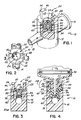
- FIG. 5 An alternative embodiment 60 of a sample site in accordance with the principles of the present invention is shown in Fig. 5.
- Sample site 60 is substantially similar to sample site 10 with the exception of the provision of a modified split luer connector.
- the entire surface of top wall 22 may be completely freed from obstruction by placing the split luer in an inoperative position.
- the split luer of embodiment 60 is provided by a pair of hinge arms 62, 64 connected such as by sonic welding or glue to bottom wall 65 of housing 12 and defining at their extremities a pair of female luer connector portions or flanged arms 66, 68.
- Hinge arms 62, 64 may be living hinges and are normally in an inoperative position shown in dashed line in Fig. 5 with arms 66, 68 outwardly of housing 12 so as to expose the entirety of top wall 22 and seal member outer surface 40 (as well as the inner walls 70 of arms 66, 68) to be easily and readily wiped clean for purposes of disinfection.
- Hinge arms 62, 64 are thickened as at 72 adjacent flanged arms 66, 68 to provide a convenient place for a clinician (not shown) to grip hinge arms 62, 64 and compress them together to bring female luer connector portions 66, 68 into an operative position shown in solid line in Fig. 5 to provide the female luer connector function for receiving a male luer connector 28 as in the case of connector portions 46, 48 described in connection with sample site 10.
- hinge arms 62, 64 urge the split luer apart into the inoperative position.
- the inner wall 70 and flange 74 of each flanged arm 66, 68 comprise about twenty-five percent (25%) of the circumference of a female luer connector cylinder and flange, or about fifty percent (50%) total.
- FIG. 6 A yet further alternative embodiment 80 of a sample site in accordance with the present invention is shown in Fig. 6.
- Sample site 80 is substantially similar to sample site 70 with the exception of the mechanism for moving female luer connector portions 66, 68 between the operative and inoperative positions shown in solid and dashed line, respectively.
- a frame member 82 is slidably supported on an annular extension 84 attached to bottom 65 of housing 12. Attached to frame member 82 are a pair of hinge arms 86, 88 with shelves 90, 92 carrying flanged arms 66, 68, respectively.
- Hinge arms 86, 88 are normally biased toward side wall 94 of housing 12, such that with frame member 82 slid against bottom 65, shelves 90, 92 pass over housing top wall 22 to position flanged arms 66, 68 into the operative position adjacent aperture 24 to provide the female luer connector function.
- frame member 82 is slid away from bottom 65 toward flange wall 96 of annular extension 84.
- top wall 22 and shelves 90, 92 cooperate to urge hinge arms 86, 88 outwardly of housing 12 and away from aperture 24 allowing flanged arms 66, 68 to ride astride housing side wall 94 into the inoperative position completely exposing access port 20 for disinfecting such as by wiping a disinfectant material thereacross.
- Hinge arms 86, 88 are thickened top and bottom as at 98, 100 to facilitate sliding frame member 82 by finger pressure there-against in the direction desired to slide frame member 82.
- hinge arms 86, 88 thus move in a direction parallel lumen 34 and transverse liquid path 14.
- the hinge arms could alternatively be mounted to slide parallel liquid path 14 and transverse lumen 34.
- a split liner arrangement to simulate a female luer connector, but without the reservoir which would otherwise impede ready access to access port 20 including surface 40 of seal member 38 and the adjacent annular portion of top wall 22 completely surrounding exposed surface 40 for disinfecting thereof, to reduce the likelihood that contamination or bacterial growth might occur.
- housing 12 has been shown as a T-connection, the access port and split luer combination of the present invention may be provided in other types of sample sites.
- the liquid path within housing 12 may be coaxial with lumen 34 rather than transverse thereto and may have only one of ports 16, 18 connected thereto.
- ports 16 and 18 could form part of a Y-connector rather than a T-connector.
- the flush mounted needleless access port and split luer lock arrangement could also be provided at each of ports 16, 18.
- System 150 includes a catheter 152 for insertion into a patient's blood vessel and connected in a series via tubing 154 to a bag 156 of saline solution. Bag 156 is wrapped in a pressure cuff 158 which may be inflated by an inflation squeeze bulb 160 through a stopcock 162. The solution flows out of bag 156 through conventional drip chamber 164.
- a roller clamp 166 may be mounted on tubing 154 adjacent drip chamber 164 in order to selectively block the flow of solution from bag 156 toward the patient. Connected immediately downstream of roller clamp 166 is a shunted stopcock 168 coupled to a waste collection bag 170.
- a flush device 172 Downstream of stopcock 168 is a flush device 172, pressure transducer 174, and three-way stopcock 176. Pressure transducer 174 is electrically connected to a monitor 178 by cable 180 for monitoring the patient's blood pressure.
- the sample site is situated between catheter 152 and three-way stopcock 176 by coupling port 16 to catheter 152 and port 18 to stopcock 176 to continue the in-line fluid path between bag 156 and catheter 152.
- Syringe 44 may be connected in fluid communication therewith by first wiping access port 20 with a disinfectant and then, if they are movable, placing the female luer connector portions of the sample site into the operative position.
- the male luer connector 28 is then fitted to access port 20 by inserting tip 26 thereof between the inner walls of the split luer and into the aperture to deflect seal member 38 and open the valve assembly under pressure of tip 26 to reveal lumen 34 and provide a fluid path between syringe 44 and liquid path 14 coupled to catheter 152.
- the cuff 58 thereof may be rotated onto the flanges of the split luer to maintain the connection.
- syringe 44 is removed by withdrawing male luer connector tip 26, allowing seal member 38 to reclose.
- the access port 20 will also be accessible (or made accessible by movement of the female luer connector portions to the inoperative position) to allow access port 20 to again be disinfected by wiping thereacross.
- a needleless connector sample site in which the access port is generally unobstructed to provide wiping access for disinfecting, while eliminating the risk of needle sticks common to needle-based sample sites and to improve sterility and reduce risk of infection otherwise feared from prior needleless connector sample sites.
- sample site may be utilized as an injection site when coupled to the venous side of a patient's circulatory system, as a sample port when connected to the arterial side, or as a link to connect an exterior fluidic system to an otherwise closed fluidic system without opening the closed system, thereby avoiding the possibility of reflux in the closed system.
- Reference to sample site will thus be appreciated as a reference to any of the above.
- the blunt cannula could be shrouded or unshrouded. In the former, the shroud (not shown) may be receivable over side wall 94 of housing 12. In the latter, tip 26 may be a typical male luer slip cannula at the end of syringe 44, but without threaded cuff 58. In either event, the split luer may either be merely a pair of unflanged arms or could be eliminated altogether.
Landscapes
- Health & Medical Sciences (AREA)
- Heart & Thoracic Surgery (AREA)
- Animal Behavior & Ethology (AREA)
- General Health & Medical Sciences (AREA)
- Anesthesiology (AREA)
- Biomedical Technology (AREA)
- Hematology (AREA)
- Life Sciences & Earth Sciences (AREA)
- Pulmonology (AREA)
- Engineering & Computer Science (AREA)
- Public Health (AREA)
- Veterinary Medicine (AREA)
- Infusion, Injection, And Reservoir Apparatuses (AREA)
- Medicines That Contain Protein Lipid Enzymes And Other Medicines (AREA)
- Measurement Of The Respiration, Hearing Ability, Form, And Blood Characteristics Of Living Organisms (AREA)
- Sampling And Sample Adjustment (AREA)
- Other Investigation Or Analysis Of Materials By Electrical Means (AREA)
Claims (14)
- Probenahmeanordnung, umfassend ein Gehäuse (12), einen sich in das Gehäuse (12) erstreckenden Flüssigkeitsweg (14), eine gelochte Außenwand (22) an dem Gehäuse (12), durch die eine abgestumpfte Kanüle in das Gehäuse (12) eintritt, um eine Fluidverbindung zu dem Flüssigkeitsweg (14) herzustellen, und ein Verschlußmittel (38), das an die Außenwandöffnung (24) angrenzt und eine Außenfläche (40) darbietet, die im wesentlichen mit der Gehäuseaußenwand (22) bündig ist, um normalerweise die Öffnung (24) gegen die Fluidverbindung mit dem Flüssigkeitsweg (14) abzuschließen, wobei das Verschlußmittel (38) unter dem Druck der in die Öffnung (24) führenden abgestumpften Kanüle zu öffnen ist, um dadurch die Fluidverbindung derselben mit dem Flüssigkeitsweg (14) zu ermöglichen, das Verschlußmittel (38) nach dem Entfernen der abgestumpften Kanüle wieder schließt, gekennzeichnet dadurch, daß ein Paar Arme (46, 48, 66, 68) zum Aufnehmen der abgestumpften Kanüle (26) sich darin um die Öffnung (24) weg von dem Gehäuse (12) erstreckt, und daß die Arme (46, 48, 66, 68) voneinander beabstandet sind, um das Reinigen des Verschlußmittels (38) durch Vorsehen eines Wischzuganges zwischen den Armen (46, 48, 66, 68) und über der Verschlußmittelaußenfläche (40) und angrenzenden Teilen der Gehäuseaußenwand (22) zu erleichtern.
- Probenahmeanordnung nach Anspruch 1, die außerdem ein Betätigungselement (32) umfaßt, das fest in dem Gehäuse (12) angeordnet ist und ein Lumen (34) dorthindurch besitzt, das in Fluidverbindung mit dem Flüssigkeitsweg (14) steht, wobei das Verschlußelement (38) unter dem Druck der in die Öffnung (24) führenden abgestumpften Kanüle in das Betätigungselement (32) bewegbar ist, um einen Kanal in dem Verschlußelement (38) zu öffnen und das Lumen (34) dadurch zu der Kanüle freizugeben, wobei die abgestumpfte Kanüle beim Eintreten in das Gehäuse (12) eine Fluidverbindung zu dem Lumen (34) herstellt und der Verschlußelementkanal mit entfernter abgestumpfter Kanüle wieder geschlossen wird, wobei die Verschlußelementaußenfläche (40) in anliegendem Kontakt mit der Gehäuseaußenwand (22) ist.
- Probenahmeanordnung nach Anspruch 1 oder 2, die außerdem Mittel (54, 74) zum Halten der abgestumpften Kanüle (26) an der Probenahmeanordnung (10, 60, 80) umfaßt.
- Probenahmeanordnung nach einem vorhergehenden Anspruch, bei der die abgestumpfte Kanüle eine Spitze (26) eines Luer-Einsteckanschlußstückes ist und Flanschmittel (54, 74) an den Armen (46, 48, 66, 68) zum Sichern des Luer-Einsteckanschlußstückes (28) an der Probenahmeanordnung (10, 60, 80) mit seiner durch die Öffnung (24) geführten Spitze (26) vorgesehen sind.
- Probenahmeanordnung nach einem vorhergehenden Anspruch, bei der die abgestumpfte Kanüle eine Spitze (26) eines Luer-Einsteckanschlußstückes (28) ist und die Arme die Form von Luer-Aufnahmeanschlußstückteilen (46, 48, 50, 54, 66, 68) haben.
- Probenahmeanordnung nach einem vorhergehenden Anspruch, bei der die Arme (46, 48) fest an entsprechenden Stellen der Gehäuseaußenfläche (22) an der Öffnung (24) angrenzend verbunden sind.
- Probenahmeanordnung nach einem der Ansprüche 1 bis 5, die außerdem Befestigungsarmmittel (62, 64, 86, 88, 90, 92) umfaßt, die zum Tragen der Arme (66, 68) an dem Gehäuse (12) entfernt von der Öffnung (24) angeschlossen sind, die in einer ersten, inaktiven Position die Arme (66, 68) weg von der Öffnung (24) drücken, um einen hindernisfreien Zugang zu der Verschlußmittelaußenfläche (40) und einem die Öffnung (24) vollständig umgebenden, ringförmigen Teil der Außenwand (22) vorzusehen, und in einer zweiten Position die Arme (66, 68) in aktive Beziehung zu der Öffnung (24) zum Aufnehmen einer abgestumpften Kanüle (26) bringen.
- Probenahmeanordnung nach Anspruch 7, bei der das Befestigungsarmmittel (62, 64) an dem Gehäuse (12) schwenkbar befestigt und normalerweise in der ersten Position ist, wobei das Befestigungsarmmittel (62, 64) durch gegen das Befestigungsarmmittel (62, 64) aufgebrachten Druck in die zweite Position bewegbar ist.
- Probenahmeanordnung nach Anspruch 7, bei der das Befestigungsarmmittel (62, 64) an dem Gehäuse (12) verschiebbar angeschlossen und in bezug auf die Öffnung (24) verschiebbar ist, wobei das Befestigungsarmmittel (86, 88) in der ersten Position von der Öffnung (24) geschoben und in der zweiten Position zu der Öffnung (24) geschoben ist.
- Probenahmeanordnung nach Anspruch 9, bei der das Gehäuse ein daran befestigtes Trägerteil (84) und ein Rahmenelement (82) umfaßt, das über dem Trägerteil (84) verschiebbar aufgenommen ist, wobei Befestigungsarmmittel (86, 88) an dem Rahmenelement (82) zur Gleitbewegung mit diesem verbunden sind, das Rahmenelement (82) zwischen einer ersten Position, in der die Befestigungsarmmittel in der zweiten, aktiven Position sind, und einer zweiten Position, in der die Befestigungsarmmittel in der ersten inaktiven Position sind, verschiebbar ist.
- Probenahmeanordnung nach Anspruch 10, bei der die gelochte Außenwand (22) und das Trägerteil (84) jeweils auf gegenüberliegenden Enden des Gehäuses (12) angeordnet sind, wobei sich die Befestigungsarmmittel (86, 88) entlang einer dazwischenliegenden Zwischenwand (94) erstrecken, die erste Position des Rahmenelementes (82) mit dem Rahmenelement (82) an die Zwischenwand (94) angrenzend definiert wird, in der die Befestigungsarmmittel (86, 88) dicht neben der Zwischenwand (94) beabstandet sind, die zweite Position des Rahmenelementes (82) mit dem Rahmenelement (82) von der Zwischenwand (94) beabstandet definiert wird, in der die Befestigungsarmmittel (86, 88) von der Zwischenwand (94) nach außen gedrückt werden und die Arme (66, 68) dicht neben der Zwischenwand (94) beabstandet sind.
- Probenahmeanordnung nach einem vorhergehenden Anspruch, bei der das Gehäuse mindestens eine mit dem Flüssigkeitsweg (14) verbundene Öffnung (16, 18) umfaßt.
- Probenahmeanordnung nach einem vorhergehenden Anspruch, bei der das Gehäuse erste und zweite, voneinander beabstandete Öffnungen (16, 18) an entsprechenden Enden des Flüssigkeitsweges umfaßt.
- Probenahmeanordnung nach Anspruch 13, bei der die ersten und zweiten Öffnungen (16, 18) auf gegenüberliegenden Seiten des Gehäuses (12) angeordnet sind, wobei die gelochte Außenwand (22) dazwischen angeordnet ist, um eine T-Verbindung zu definieren.
Priority Applications (1)
| Application Number | Priority Date | Filing Date | Title |
|---|---|---|---|
| EP94203665A EP0653221B1 (de) | 1990-09-18 | 1991-09-12 | Nadellose Injektionsstelle |
Applications Claiming Priority (3)
| Application Number | Priority Date | Filing Date | Title |
|---|---|---|---|
| US58428690A | 1990-09-18 | 1990-09-18 | |
| US584286 | 1990-09-18 | ||
| PCT/US1991/006604 WO1992004936A1 (en) | 1990-09-18 | 1991-09-12 | Needleless connector sample site |
Related Child Applications (2)
| Application Number | Title | Priority Date | Filing Date |
|---|---|---|---|
| EP94203665A Division EP0653221B1 (de) | 1990-09-18 | 1991-09-12 | Nadellose Injektionsstelle |
| EP94203665.8 Division-Into | 1994-12-16 |
Publications (2)
| Publication Number | Publication Date |
|---|---|
| EP0549730A1 EP0549730A1 (de) | 1993-07-07 |
| EP0549730B1 true EP0549730B1 (de) | 1995-07-26 |
Family
ID=24336691
Family Applications (2)
| Application Number | Title | Priority Date | Filing Date |
|---|---|---|---|
| EP94203665A Expired - Lifetime EP0653221B1 (de) | 1990-09-18 | 1991-09-12 | Nadellose Injektionsstelle |
| EP91920317A Expired - Lifetime EP0549730B1 (de) | 1990-09-18 | 1991-09-12 | Nadellose injektionsstelle |
Family Applications Before (1)
| Application Number | Title | Priority Date | Filing Date |
|---|---|---|---|
| EP94203665A Expired - Lifetime EP0653221B1 (de) | 1990-09-18 | 1991-09-12 | Nadellose Injektionsstelle |
Country Status (7)
| Country | Link |
|---|---|
| EP (2) | EP0653221B1 (de) |
| JP (1) | JPH06500941A (de) |
| AT (2) | ATE412444T1 (de) |
| AU (1) | AU8901891A (de) |
| CA (1) | CA2089750A1 (de) |
| DE (2) | DE69111610D1 (de) |
| WO (1) | WO1992004936A1 (de) |
Families Citing this family (13)
| Publication number | Priority date | Publication date | Assignee | Title |
|---|---|---|---|---|
| US5251873B1 (en) * | 1992-06-04 | 1995-05-02 | Vernay Laboratories | Medical coupling site. |
| US5533708A (en) * | 1992-06-04 | 1996-07-09 | Vernay Laboratories, Inc. | Medical coupling site valve body |
| US5501426A (en) * | 1992-06-04 | 1996-03-26 | Vernay Laboratories, Inc. | Medical coupling site valve body |
| US5242393A (en) * | 1992-06-18 | 1993-09-07 | Becton, Dickinson And Company | Valved blunt cannula injection site |
| US5300034A (en) * | 1992-07-29 | 1994-04-05 | Minnesota Mining And Manufacturing Company | Iv injection site for the reception of a blunt cannula |
| WO1994015665A1 (en) * | 1993-01-13 | 1994-07-21 | Medex, Inc. | Needleless sample set |
| US6068011A (en) * | 1993-10-13 | 2000-05-30 | Paradis; Joseph R. | Control of fluid flow |
| US5470319A (en) | 1994-06-20 | 1995-11-28 | Critical Device Corporation | Needleless injection site |
| US5814024A (en) * | 1996-11-27 | 1998-09-29 | Elcam Plastics | Needleless valve |
| US5807348A (en) * | 1996-11-27 | 1998-09-15 | Elcam Plastics | Needleless valve |
| US5957898A (en) | 1997-05-20 | 1999-09-28 | Baxter International Inc. | Needleless connector |
| US6908459B2 (en) | 2001-12-07 | 2005-06-21 | Becton, Dickinson And Company | Needleless luer access connector |
| US8197452B2 (en) * | 2006-07-28 | 2012-06-12 | Becton, Dickinson And Company | Vascular access device non-adhering surfaces |
Family Cites Families (5)
| Publication number | Priority date | Publication date | Assignee | Title |
|---|---|---|---|---|
| DE3303718C1 (de) * | 1983-02-04 | 1984-10-04 | B. Braun Melsungen Ag, 3508 Melsungen | Injektionsventil für Punktionsgeräte oder Infusionseinrichtungen |
| DE3732515A1 (de) * | 1987-09-26 | 1989-04-06 | Joka Kathetertechnik Gmbh | Vorrichtung zum einspritzen und/oder entnehmen von fluessigkeiten |
| EP0354947B1 (de) * | 1988-01-25 | 1994-07-20 | BAXTER INTERNATIONAL INC. (a Delaware corporation) | Vorgeschlitzte injektionsvorrichtung sowie konische kanüle |
| US4874377A (en) * | 1988-05-26 | 1989-10-17 | Davis Newgard Revocable Family Living Trust | Self-occluding intravascular cannula assembly |
| US5006114A (en) * | 1990-04-20 | 1991-04-09 | Rogers Bobby E | Medical valve assembly |
-
1991
- 1991-09-12 AU AU89018/91A patent/AU8901891A/en not_active Abandoned
- 1991-09-12 AT AT94203665T patent/ATE412444T1/de not_active IP Right Cessation
- 1991-09-12 AT AT91920317T patent/ATE125454T1/de not_active IP Right Cessation
- 1991-09-12 EP EP94203665A patent/EP0653221B1/de not_active Expired - Lifetime
- 1991-09-12 DE DE69111610T patent/DE69111610D1/de not_active Expired - Lifetime
- 1991-09-12 JP JP3518439A patent/JPH06500941A/ja active Pending
- 1991-09-12 DE DE69133607T patent/DE69133607D1/de not_active Expired - Lifetime
- 1991-09-12 EP EP91920317A patent/EP0549730B1/de not_active Expired - Lifetime
- 1991-09-12 CA CA002089750A patent/CA2089750A1/en not_active Abandoned
- 1991-09-12 WO PCT/US1991/006604 patent/WO1992004936A1/en not_active Ceased
Also Published As
| Publication number | Publication date |
|---|---|
| DE69111610D1 (de) | 1995-08-31 |
| EP0653221B1 (de) | 2008-10-29 |
| CA2089750A1 (en) | 1992-03-19 |
| AU8901891A (en) | 1992-04-15 |
| EP0653221A1 (de) | 1995-05-17 |
| JPH06500941A (ja) | 1994-01-27 |
| EP0549730A1 (de) | 1993-07-07 |
| DE69133607D1 (de) | 2008-12-11 |
| ATE125454T1 (de) | 1995-08-15 |
| ATE412444T1 (de) | 2008-11-15 |
| WO1992004936A1 (en) | 1992-04-02 |
Similar Documents
| Publication | Publication Date | Title |
|---|---|---|
| US5203775A (en) | Needleless connector sample site | |
| US20230241313A1 (en) | Infusion and blood collection device | |
| EP0549730B1 (de) | Nadellose injektionsstelle | |
| US4510933A (en) | Suction adapter and medical draining set and method of using a tracheal draining device | |
| US4838855A (en) | Blood aspiration assembly and method | |
| US5417673A (en) | Whole blood sample needleless sample site | |
| CA2346468C (en) | Swabbable needleless low reflux injection port system | |
| US7150740B2 (en) | Urinary catheter system | |
| KR0179030B1 (ko) | 상처배수 튜브와 저장기를 연결하는 커넥터 | |
| JPS62167571A (ja) | 液体の採取又は注入装置 | |
| US20060155213A1 (en) | Self flushing luer activated blood sampling devices | |
| US20140343456A1 (en) | Peripheral blood sampling methods and devices | |
| EP0479890A1 (de) | Arterielles/venöses fluidtransfersystem | |
| US20010039403A1 (en) | Positive flow generator for indwelling medical fluid systems | |
| WO1995015194A1 (en) | Slit septum needleless site with check valve | |
| JPH05200098A (ja) | 閉鎖系コネクタ組立体 | |
| WO2005084548A1 (en) | Diaphragm-based reservoir for a closed blood sampling system | |
| US5827238A (en) | Roller clamp-connector assembly | |
| CN222549203U (zh) | 用于管线抽取冲洗和血液采集的系统 | |
| CN110582323B (zh) | 用来进入人体或动物体血管系统的植入式进入装置 | |
| EP4090396B1 (de) | Externes endgerät und verfahren zu seiner verbindung mit durchflussleitungen | |
| KR100517199B1 (ko) | 1회용 혈관 수지침 | |
| WO2015117126A1 (en) | Medical valve |
Legal Events
| Date | Code | Title | Description |
|---|---|---|---|
| PUAI | Public reference made under article 153(3) epc to a published international application that has entered the european phase |
Free format text: ORIGINAL CODE: 0009012 |
|
| 17P | Request for examination filed |
Effective date: 19930401 |
|
| AK | Designated contracting states |
Kind code of ref document: A1 Designated state(s): AT BE CH DE DK ES FR GB GR IT LI LU NL SE |
|
| 17Q | First examination report despatched |
Effective date: 19930907 |
|
| GRAA | (expected) grant |
Free format text: ORIGINAL CODE: 0009210 |
|
| AK | Designated contracting states |
Kind code of ref document: B1 Designated state(s): AT BE CH DE DK ES FR GB GR IT LI LU NL SE |
|
| PG25 | Lapsed in a contracting state [announced via postgrant information from national office to epo] |
Ref country code: IT Free format text: LAPSE BECAUSE OF FAILURE TO SUBMIT A TRANSLATION OF THE DESCRIPTION OR TO PAY THE FEE WITHIN THE PRE;WARNING: LAPSES OF ITALIAN PATENTS WITH EFFECTIVE DATE BEFORE 2007 MAY HAVE OCCURRED AT ANY TIME BEFORE 2007. THE CORRECT EFFECTIVE DATE MAY BE DIFFERENT FROM THE ONE RECORDED.SCRIBED TIME-LIMIT Effective date: 19950726 Ref country code: DK Effective date: 19950726 Ref country code: GR Free format text: LAPSE BECAUSE OF FAILURE TO SUBMIT A TRANSLATION OF THE DESCRIPTION OR TO PAY THE FEE WITHIN THE PRESCRIBED TIME-LIMIT Effective date: 19950726 Ref country code: CH Effective date: 19950726 Ref country code: BE Effective date: 19950726 Ref country code: AT Effective date: 19950726 Ref country code: LI Effective date: 19950726 Ref country code: NL Free format text: LAPSE BECAUSE OF NON-PAYMENT OF DUE FEES Effective date: 19950726 Ref country code: FR Effective date: 19950726 Ref country code: ES Free format text: THE PATENT HAS BEEN ANNULLED BY A DECISION OF A NATIONAL AUTHORITY Effective date: 19950726 |
|
| REF | Corresponds to: |
Ref document number: 125454 Country of ref document: AT Date of ref document: 19950815 Kind code of ref document: T |
|
| XX | Miscellaneous (additional remarks) |
Free format text: TEILANMELDUNG 94203665.8 EINGEREICHT AM 12/09/91. |
|
| REF | Corresponds to: |
Ref document number: 69111610 Country of ref document: DE Date of ref document: 19950831 |
|
| PG25 | Lapsed in a contracting state [announced via postgrant information from national office to epo] |
Ref country code: LU Free format text: LAPSE BECAUSE OF NON-PAYMENT OF DUE FEES Effective date: 19950930 |
|
| PG25 | Lapsed in a contracting state [announced via postgrant information from national office to epo] |
Ref country code: GB Effective date: 19951026 Ref country code: SE Effective date: 19951026 |
|
| PG25 | Lapsed in a contracting state [announced via postgrant information from national office to epo] |
Ref country code: DE Effective date: 19951027 |
|
| EN | Fr: translation not filed | ||
| NLV1 | Nl: lapsed or annulled due to failure to fulfill the requirements of art. 29p and 29m of the patents act | ||
| PLBE | No opposition filed within time limit |
Free format text: ORIGINAL CODE: 0009261 |
|
| STAA | Information on the status of an ep patent application or granted ep patent |
Free format text: STATUS: NO OPPOSITION FILED WITHIN TIME LIMIT |
|
| GBPC | Gb: european patent ceased through non-payment of renewal fee |
Effective date: 19951026 |
|
| 26N | No opposition filed |