EP0549821A1 - Procédé pour opérer le pierrage de forages et tête de pierrage pour la mise en oeuvre du procédé - Google Patents
Procédé pour opérer le pierrage de forages et tête de pierrage pour la mise en oeuvre du procédé Download PDFInfo
- Publication number
- EP0549821A1 EP0549821A1 EP91122092A EP91122092A EP0549821A1 EP 0549821 A1 EP0549821 A1 EP 0549821A1 EP 91122092 A EP91122092 A EP 91122092A EP 91122092 A EP91122092 A EP 91122092A EP 0549821 A1 EP0549821 A1 EP 0549821A1
- Authority
- EP
- European Patent Office
- Prior art keywords
- honing
- bore
- bores
- tool
- honing tool
- Prior art date
- Legal status (The legal status is an assumption and is not a legal conclusion. Google has not performed a legal analysis and makes no representation as to the accuracy of the status listed.)
- Granted
Links
- 238000000034 method Methods 0.000 title claims abstract description 28
- 239000004575 stone Substances 0.000 claims description 37
- 238000003754 machining Methods 0.000 claims description 11
- 239000000463 material Substances 0.000 claims description 4
- 239000011248 coating agent Substances 0.000 description 3
- 238000000576 coating method Methods 0.000 description 3
- VYZAMTAEIAYCRO-UHFFFAOYSA-N Chromium Chemical compound [Cr] VYZAMTAEIAYCRO-UHFFFAOYSA-N 0.000 description 1
- 230000000295 complement effect Effects 0.000 description 1
- 238000004519 manufacturing process Methods 0.000 description 1
- 239000002184 metal Substances 0.000 description 1
Images

Classifications
-
- B—PERFORMING OPERATIONS; TRANSPORTING
- B24—GRINDING; POLISHING
- B24B—MACHINES, DEVICES, OR PROCESSES FOR GRINDING OR POLISHING; DRESSING OR CONDITIONING OF ABRADING SURFACES; FEEDING OF GRINDING, POLISHING, OR LAPPING AGENTS
- B24B33/00—Honing machines or devices; Accessories therefor
- B24B33/02—Honing machines or devices; Accessories therefor designed for working internal surfaces of revolution, e.g. of cylindrical or conical shapes
Definitions
- the invention relates to a method for honing two or more aligned and connected bores within the workpiece according to the preamble of claim 1 and a honing tool for performing the method according to the preamble of claim 8.
- Aligned holes within a workpiece in particular double holes, which are connected, for example, by a cavity within the workpiece, can be machined in a known manner with a honing tool that has one or more very long honing stones, whereby both holes are honed at the same time, as is the case with single holes is common.
- a honing tool that has one or more very long honing stones, whereby both holes are honed at the same time, as is the case with single holes is common.
- the invention has for its object to design the method and the honing tool for machining two or more aligned bores in such a way that very close tolerances with regard to the dimensions and shape can be maintained on all finished bores.
- the successive machining of the individual bores of double or multiple bores makes it possible to individually adapt the honing process to each of the bores, the simultaneous guidance of the honing tool in another bore providing additional support with an axial distance from the working part of the honing tool, which increases the accuracy of the Gauges of the machined bore contribute significantly.
- the hole in which the honing tool slides during machining can create a cavity in the workpiece be that connects two successive holes and is designed for example as a hole with a larger width than the holes to be machined.
- the honing tool is expediently guided during the machining of the one bore in the bore to be machined in the next work step, and in the next work step the finished bore can serve as a guide bore for the honing tool.
- the same honing tool can be used for this, the stroke position of which is changed after the end of the first working step in accordance with the axial distance between the successive bores.
- the use of two or - depending on the number of holes - several honing tools is recommended, the respective honing tool intended for one of the holes being machined in another hole, in particular in another honing tool to be machined hole.
- the honing tool according to the invention has at least one honing stone and at least one guide section on the circumference, which are axially spaced from one another.
- the guide section is expediently longer than the honing stone. It can be a guide part formed by the tool body, which is provided with a wear-resistant sliding coating; However, a guide bar, which is arranged on the tool body and is made of wear-resistant material, can also be provided as the guide section and is preferably radially adjustable.
- Fig. 1 shows in the middle part of the drawing schematically in axial section a workpiece 1, which contains aligned bores 2 and 3, have the same diameter and are connected by a cavity 4, which is designed, for example, as a bore which has a larger diameter than that both holes 2 and 3.
- a single honing tool 5 is provided, which is shown in the left part of the drawing in an upper stroke position and in the right part of the drawing in a lower stroke position - in each case in partial axial section.
- a honing stone 6 is suitably inserted into a longitudinal slot of the tool body and can be advanced radially outwards against the wall of the bore to be machined by means of a feed rod 7.
- the delivery bar is for this purpose axially displaceable in a central bore of the honing tool 5 and lies with a wedge surface 8 on a complementary wedge surface of the honing stone 6.
- the honing stone 6 is arranged about half the length of the honing tool 5. Above and below the honing stone 6 and at an axial distance from it, one of two guide sections 9 and 10 is provided, which are guide parts formed by the tool body 11 and each have a wear-resistant sliding coating 12.
- the guide sections 9 and 10 each have a greater length than the honing stone 6 and from it an axial distance which is somewhat smaller than the axial distance between the bores 2 and 3 of the workpiece 1.
- the honing stone 6 is approximately the same length as each of the two Holes 2 and 3.
- a plurality of honing stones 6 can be arranged in a known manner distributed over the circumference of the tool body 11, wherein a guide bar can also be arranged between two honing stones.
- a plurality of guide sections 9 and 10 are also expediently distributed over the circumference of the tool body 11.
- separate guide strips can also be provided, which consist of wear-resistant material, for example of hard metal, hard chrome, plastic or similar materials.
- Such guide strips like the honing stone 6, can be inserted appropriately in the longitudinal slots of the tool body and can be fed radially outwards, for which purpose an additional feed rod with corresponding wedge surfaces can be provided in a known manner or the feed rod 7 can be designed accordingly.
- the two holes 2 and 3 are honed in two steps according to the inventive method.
- the bore 2 is first machined, the honing tool 5 having the stroke position shown in the left part of the drawing.
- the honing tool is driven as usual with a predetermined stroke alternating up and down and at the same time rotating about its longitudinal axis.
- the honing tool with its lower guide section 10 or with a plurality of such guide sections, which are arranged distributed over the circumference of the tool body, is slidably guided in the lower bore 3. Since the guide section 10 is longer than the honing stone 6, it is constantly in the bore 3, i.e.
- the honing stone 6 with the usual overflow namely up to about a third of its length, from the bore 2 extends above and below.
- the honing tool is therefore constantly supported at an axial distance from its working part, which is formed by the honing stone 6 or more honing stones, during processing. This guidance and support contributes significantly to the shape accuracy of the machined hole. Since the length of the honing stone 6 or more of these honing stones is adapted to the length of the bore 2 to be machined, known correction methods can also be used which counteract shape errors of the machined bore, for example by changing the stroke position.
- the stroke position of the honing tool 5 is adjusted downward, so that the working part of the honing tool with the honing stone (s) 6 now lies in the lower bore 3, as can be seen from the right part of FIG. 1.
- the honing process proceeds in the same way as in the first step, the honing tool 5 now being guided and supported with its upper guide section 9 in the finished bore 2.
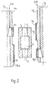
- FIG. 2 shows in the left and right part of the drawing two different honing tools 5A and 5B, which are provided for the successive machining of the bores 2 and 3.
- the workpiece 1 to be machined is shown in the same embodiment as in FIG. 1, that is to say has two bores 2 and 3 of the same diameter connected by a cavity 4.
- machining with two tools 5A and 5B is intended in particular for honing stepped bores in which the aligned bores therefore have different diameters.
- the honing tool 5A has one or more honing stones 6a, the length of which corresponds approximately to the length of the bore 2.
- the honing tool 5B is provided in the same way with one or more honing stones 6b, the length of which is adapted to the length of the bore 3.
- the honing stones 6a and 6b are each radially adjustable by means of a feed rod 7a or 7b.
- a guide section 10a below the honing stone 6a which is designed as a guide part formed by the tool body 11a and is provided with a sliding coating 12.
- a guide section 9a is provided above the honing stone 6b. Both guide sections 9a and 10a are longer than the associated honing stone 6b or 6a. With these honing tools, too, several honing stones and / or several guide sections can be used be distributed over the circumference of the tool body.
- the guide sections 9a and 10a can, as explained for the exemplary embodiment according to FIG. 1, also be designed as guide strips, which are expediently radially adjustable. The radial feedability in the direction of the associated bore wall enables the respective honing tool to be guided without play, independent of the diameter tolerances of the bores 2 and 3.
- the double bore 2, 3 is also honed in successive work steps.
- the honing tool 5A can be used to machine the upper bore 2, so that the guide section 10a is guided in the lower bore 3.
- the honing tool 5A is exchanged for the honing tool 5B, which now processes the lower bore 3 with the honing stone (s) 6b at approximately the same stroke position, while it is guided in the upper bore 2 and by means of the guide section (s) 9a is supported.
- the guide sections 9a and 10a are in the working position constantly in the bore 2 and 3, respectively, since they are longer than the associated honing stones.
- a honing tool can be used which has one or more honing stones of particularly great length, so that, for example in the case of a double hole, the two individual holes can be pre-honed simultaneously.
Landscapes
- Physics & Mathematics (AREA)
- Geometry (AREA)
- Engineering & Computer Science (AREA)
- Mechanical Engineering (AREA)
- Finish Polishing, Edge Sharpening, And Grinding By Specific Grinding Devices (AREA)
Priority Applications (2)
| Application Number | Priority Date | Filing Date | Title |
|---|---|---|---|
| EP19910122092 EP0549821B1 (fr) | 1991-12-22 | 1991-12-22 | Procédé pour opérer le pierrage de forages et tête de pierrage pour la mise en oeuvre du procédé |
| DE59105942T DE59105942D1 (de) | 1991-12-22 | 1991-12-22 | Verfahren zum Honen von Bohrungen und Honwerkzeug zur Durchführung des Verfahrens. |
Applications Claiming Priority (1)
| Application Number | Priority Date | Filing Date | Title |
|---|---|---|---|
| EP19910122092 EP0549821B1 (fr) | 1991-12-22 | 1991-12-22 | Procédé pour opérer le pierrage de forages et tête de pierrage pour la mise en oeuvre du procédé |
Publications (2)
| Publication Number | Publication Date |
|---|---|
| EP0549821A1 true EP0549821A1 (fr) | 1993-07-07 |
| EP0549821B1 EP0549821B1 (fr) | 1995-07-05 |
Family
ID=8207469
Family Applications (1)
| Application Number | Title | Priority Date | Filing Date |
|---|---|---|---|
| EP19910122092 Expired - Lifetime EP0549821B1 (fr) | 1991-12-22 | 1991-12-22 | Procédé pour opérer le pierrage de forages et tête de pierrage pour la mise en oeuvre du procédé |
Country Status (2)
| Country | Link |
|---|---|
| EP (1) | EP0549821B1 (fr) |
| DE (1) | DE59105942D1 (fr) |
Cited By (2)
| Publication number | Priority date | Publication date | Assignee | Title |
|---|---|---|---|---|
| DE4439381A1 (de) * | 1994-11-04 | 1996-05-09 | Nagel Masch Werkzeug | Honwerkzeug |
| WO2019068462A1 (fr) * | 2017-10-02 | 2019-04-11 | Gehring Technologies Gmbh | Procédé permettant le rodage d'un stator et machine pour mettre en œuvre le procédé |
Families Citing this family (3)
| Publication number | Priority date | Publication date | Assignee | Title |
|---|---|---|---|---|
| US7621327B2 (en) | 2007-10-31 | 2009-11-24 | Baker Hughes Incorporated | Downhole seal bore repair device |
| DE102011087074B4 (de) * | 2011-11-25 | 2024-05-08 | Bayerische Motoren Werke Aktiengesellschaft | Honwerkzeug und Verfahren zum Honen mit dem Honwerkzeug |
| DE102013223293A1 (de) | 2013-11-15 | 2015-05-21 | Gehring Technologies Gmbh | Honwerkzeug und Verfahren zum Bearbeiten mehrerer koaxialer Bohrungen |
Citations (1)
| Publication number | Priority date | Publication date | Assignee | Title |
|---|---|---|---|---|
| DE2627886A1 (de) * | 1976-06-22 | 1978-01-05 | Volkswagenwerk Ag | Verfahren zum herstellen von bohrungen hoher oberflaechenguete |
-
1991
- 1991-12-22 EP EP19910122092 patent/EP0549821B1/fr not_active Expired - Lifetime
- 1991-12-22 DE DE59105942T patent/DE59105942D1/de not_active Expired - Lifetime
Patent Citations (1)
| Publication number | Priority date | Publication date | Assignee | Title |
|---|---|---|---|---|
| DE2627886A1 (de) * | 1976-06-22 | 1978-01-05 | Volkswagenwerk Ag | Verfahren zum herstellen von bohrungen hoher oberflaechenguete |
Non-Patent Citations (1)
| Title |
|---|
| PATENT ABSTRACTS OF JAPAN vol. 5, no. 39 (M-59)(711) 14. März 1981 & JP-A-55 164 471 ( TOKYO SHIBAURA DENKI K. K. ) 22. Dezember 1980 * |
Cited By (2)
| Publication number | Priority date | Publication date | Assignee | Title |
|---|---|---|---|---|
| DE4439381A1 (de) * | 1994-11-04 | 1996-05-09 | Nagel Masch Werkzeug | Honwerkzeug |
| WO2019068462A1 (fr) * | 2017-10-02 | 2019-04-11 | Gehring Technologies Gmbh | Procédé permettant le rodage d'un stator et machine pour mettre en œuvre le procédé |
Also Published As
| Publication number | Publication date |
|---|---|
| EP0549821B1 (fr) | 1995-07-05 |
| DE59105942D1 (de) | 1995-08-10 |
Similar Documents
| Publication | Publication Date | Title |
|---|---|---|
| AT396663B (de) | Spannbüchse, insbesondere federnde klemmhülse | |
| EP0295453A2 (fr) | Méthode et outil d'usinage des surfaces de machines à combustion interne | |
| DE102014108219A1 (de) | Rotationswerkzeug sowie Verfahren zur Herstellung eines Rotationswerkzeugs | |
| DE10358150A1 (de) | Verfahren zum Honen von Bohrungen | |
| DE3415332A1 (de) | Verfahren zum herstellen eines raeumwerkzeugs | |
| DE4402843C2 (de) | Innenräumwerkzeug | |
| EP0535201B1 (fr) | Procede a honer d'alesages | |
| EP3768452B1 (fr) | Foret long comportant plusieurs éléments de formation de copeaux et des cavités dans la face de coupe | |
| WO2019052850A1 (fr) | Outil de rugosification et procédé de fabrication associé | |
| EP0549821B1 (fr) | Procédé pour opérer le pierrage de forages et tête de pierrage pour la mise en oeuvre du procédé | |
| EP0219825B1 (fr) | Méthode, machine et outil pour le rodage de pièces | |
| EP0264599B1 (fr) | Outil d'alésage | |
| DE3734734C2 (fr) | ||
| DE69228809T2 (de) | Maschine zum schaerfen von saegeblaettern | |
| DE102008047782A1 (de) | Vorrichtung zum Rundkneten von Werkstücken | |
| DE3329731C2 (fr) | ||
| WO2023089025A1 (fr) | Outil de pierrage et procédé de production d'un outil de pierrage | |
| DE3202031C2 (de) | Bohrstange | |
| DE3738074C2 (fr) | ||
| EP3658319B1 (fr) | Outil d'usinage par enlèvement de copeaux et procédé pour l'usinage d'une roulement d'un palier | |
| DE4439381A1 (de) | Honwerkzeug | |
| DE3011670C2 (fr) | ||
| DE19611891C2 (de) | Ausdrehwerkzeug für die Vor- und Fertigbearbeitung einer Bohrungsoberfläche | |
| DE3317026C1 (de) | Kopierfräsvorrichtung zum Fräsen von Beschlagsaussparungen in Tür- und Fensterprofile | |
| EP0549820A1 (fr) | Tête de pierrage |
Legal Events
| Date | Code | Title | Description |
|---|---|---|---|
| PUAI | Public reference made under article 153(3) epc to a published international application that has entered the european phase |
Free format text: ORIGINAL CODE: 0009012 |
|
| 17P | Request for examination filed |
Effective date: 19921116 |
|
| AK | Designated contracting states |
Kind code of ref document: A1 Designated state(s): DE DK ES FR GB IT SE |
|
| 17Q | First examination report despatched |
Effective date: 19930907 |
|
| GRAA | (expected) grant |
Free format text: ORIGINAL CODE: 0009210 |
|
| AK | Designated contracting states |
Kind code of ref document: B1 Designated state(s): DE DK ES FR GB IT SE |
|
| PG25 | Lapsed in a contracting state [announced via postgrant information from national office to epo] |
Ref country code: ES Free format text: THE PATENT HAS BEEN ANNULLED BY A DECISION OF A NATIONAL AUTHORITY Effective date: 19950705 Ref country code: IT Free format text: LAPSE BECAUSE OF FAILURE TO SUBMIT A TRANSLATION OF THE DESCRIPTION OR TO PAY THE FEE WITHIN THE PRE;WARNING: LAPSES OF ITALIAN PATENTS WITH EFFECTIVE DATE BEFORE 2007 MAY HAVE OCCURRED AT ANY TIME BEFORE 2007. THE CORRECT EFFECTIVE DATE MAY BE DIFFERENT FROM THE ONE RECORDED.SCRIBED TIME-LIMIT Effective date: 19950705 Ref country code: GB Effective date: 19950705 Ref country code: FR Effective date: 19950705 Ref country code: DK Effective date: 19950705 |
|
| REF | Corresponds to: |
Ref document number: 59105942 Country of ref document: DE Date of ref document: 19950810 |
|
| PG25 | Lapsed in a contracting state [announced via postgrant information from national office to epo] |
Ref country code: SE Effective date: 19951005 |
|
| EN | Fr: translation not filed | ||
| GBV | Gb: ep patent (uk) treated as always having been void in accordance with gb section 77(7)/1977 [no translation filed] |
Effective date: 19950705 |
|
| PLBE | No opposition filed within time limit |
Free format text: ORIGINAL CODE: 0009261 |
|
| STAA | Information on the status of an ep patent application or granted ep patent |
Free format text: STATUS: NO OPPOSITION FILED WITHIN TIME LIMIT |
|
| 26N | No opposition filed | ||
| PGFP | Annual fee paid to national office [announced via postgrant information from national office to epo] |
Ref country code: DE Payment date: 20110203 Year of fee payment: 20 |
|
| REG | Reference to a national code |
Ref country code: DE Ref legal event code: R071 Ref document number: 59105942 Country of ref document: DE |
|
| REG | Reference to a national code |
Ref country code: DE Ref legal event code: R071 Ref document number: 59105942 Country of ref document: DE |
|
| PG25 | Lapsed in a contracting state [announced via postgrant information from national office to epo] |
Ref country code: DE Free format text: LAPSE BECAUSE OF EXPIRATION OF PROTECTION Effective date: 20111223 |