EP0549825B1 - Machine à forger - Google Patents
Machine à forger Download PDFInfo
- Publication number
- EP0549825B1 EP0549825B1 EP91122359A EP91122359A EP0549825B1 EP 0549825 B1 EP0549825 B1 EP 0549825B1 EP 91122359 A EP91122359 A EP 91122359A EP 91122359 A EP91122359 A EP 91122359A EP 0549825 B1 EP0549825 B1 EP 0549825B1
- Authority
- EP
- European Patent Office
- Prior art keywords
- rams
- shafts
- actuating devices
- stroke
- drives
- Prior art date
- Legal status (The legal status is an assumption and is not a legal conclusion. Google has not performed a legal analysis and makes no representation as to the accuracy of the status listed.)
- Expired - Lifetime
Links
- 238000005242 forging Methods 0.000 title claims abstract description 13
- 230000008878 coupling Effects 0.000 claims description 6
- 238000010168 coupling process Methods 0.000 claims description 6
- 238000005859 coupling reaction Methods 0.000 claims description 6
- 238000006073 displacement reaction Methods 0.000 claims 1
- 230000005855 radiation Effects 0.000 abstract description 5
- 230000007246 mechanism Effects 0.000 abstract 3
- 230000004048 modification Effects 0.000 description 4
- 238000012986 modification Methods 0.000 description 4
- 238000010276 construction Methods 0.000 description 1
- 238000007789 sealing Methods 0.000 description 1
- 239000007787 solid Substances 0.000 description 1
- 125000006850 spacer group Chemical group 0.000 description 1
Images


Classifications
-
- B—PERFORMING OPERATIONS; TRANSPORTING
- B21—MECHANICAL METAL-WORKING WITHOUT ESSENTIALLY REMOVING MATERIAL; PUNCHING METAL
- B21J—FORGING; HAMMERING; PRESSING METAL; RIVETING; FORGE FURNACES
- B21J7/00—Hammers; Forging machines with hammers or die jaws acting by impact
- B21J7/02—Special design or construction
- B21J7/14—Forging machines working with several hammers
Definitions
- Forging workpieces emphasized along the longitudinal axis are used forging machines which are equipped with four X-shaped rams arranged in one plane, offset by 90 ° from each other, acting radially on the workpiece guided longitudinally in the system axis and equipped with tools.
- the invention relates in particular to a forging machine of this type, as is known from EP 0 228 030 B1, in which the tappet guided in the machine frame comprises parts (in one piece or in combination) of piston-cylinder units with a stroke corresponding to the working stroke of the tappet Form stroke and in their stroke position by the piston-cylinder units supporting, adjustable to the machine frame trusses are adjustable, the transverse adjustable in their common plane by means of tool supports on the rams of tools acting on the supports depending on the setting of the stroke end position of the Ram are adjustable and lockable in such a way that the tools, which with their part of their working surface exceeding the caliber dimension are covered by a side surface of an adjacent tool, form a closed caliber in their respective stroke end position.
- the actuators whose end members (racks, link guides) are connected to the supports, are driven by shafts of motors that are attached to the crossbars adjustable in the machine frame for adjusting the stroke position of the tools, so that only the drive connection from the motor to the end member of the actuator Work stroke must be balanced.
- the tappet and its piston-cylinder unit must be provided with central through openings, or the shafts must be arranged to the side of the tappets.
- the central arrangement of the shafts requires hollow shafts in the piston-cylinder units, in order to be able to seal pistons and cylinders against each other and towards the central through openings, as can be seen in FIGS. 2, 3 and 6 of EP 0 228 030 B1.
- the construction effort is correspondingly great and the accessibility of the components is made more difficult.
- the invention is based on the last-mentioned prior art, uses the structural simplification given by this, and aims to better adapt the drive connections between the shafts and the end members of the actuating devices to the operating conditions, a goal which is the subject of EP 0 228 030 B1 forming invention was missed.
- the invention provides that the gears of the actuating devices are connected to the plungers and their drives are connected via the plunger movement compensating rotary couplings.
- the rotary couplings can be provided between the gearboxes of the actuating devices and the shafts, between the parts of split shafts or between the shafts and their drives, the rotary couplings per se allowing better protection against heat radiation and scale, but also their arrangement on more protected, heat radiation and scaling are less exposed.
- hydraulic swivel motors with pinions rotated by pistons via toothed racks are provided as drives of the adjusting devices, the pinions of which are connected on the one hand by means of telescopic shafts to the gearboxes of the adjusting devices and on the other hand to the rotary encoders which record the actuating path, the conditions of the forging operation are particularly important Corresponded accordingly, both with regard to the structural compactness and the protection of the components against scaling, heat radiation and mechanical stress.
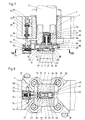
- the forging machine shown in Fig. 1 in the direction of the system axis S consists of a frame 1, which leads four X-shaped plungers 2 and combines them with their drives, so that the plunger 2 radially to the system axis S in the perpendicular to it Move the work plane.
- the frame 1 is provided on both sides at the front and at the rear with brackets 3 with which it is supported on brackets 4 of a foundation.
- Each plunger 2 is provided on the end face with a tool 5, and the tools 5 form a closed caliber in the stroke end positions of the plunger 2.
- the tools 5 are carried by supports 6 which are adjustable transversely to the axes of the plungers 2 in the working plane, and the stroke end positions of the plungers 2 are adjustable, as is known from EP 0 228 030 B1.
- the frame 1 is provided with a guide bush 7 and - as shown in FIG. 6 - with guide plates 8 which rest on flats 9 of the plunger 2 and secure it against rotation.
- the plunger 2 To drive the plunger 2 is provided at its end facing away from the support 6 with tool 5 with a bore 11 and thus forms a cylinder 12. In the bore 11, an end ring 13 with a sealing ring 14 is inserted, which surround a plunger 15. The plunger 15 is supported by a cross member 16. In the area in which the plunger 2 is designed as a cylinder 12, it is provided with a flange 17.
- a ring 20 connected to the cross member 16 via spacer bushes 18 and tie rods 19 surrounds the tappet 2 and cylinder 12 and engages behind the flange 17 and is provided with cylinder bores 21 from which plungers 22 are pressed against the flange 17 and the retraction of the tappet 2 cause while the working stroke of the plunger 2 is effected by acting on the plunger 15 in the cylinder 12.
- the stroke of the cylinder 12 to the plunger 15 and the plunger 22 in the cylinder bores 21 is limited to the working stroke of the plunger 2.
- the cross members 16 are in the plunger stroke direction to the frame 1 of the forging machine adjustable.
- each cross member 16 is connected to the frame 1 by four anchors 23 by means of threaded nuts 24 which are rotatably mounted in the cross member 16 supporting against the pressing force on the plunger 15, the armature 23 can be rotated on the threaded shafts 25.
- the threaded nuts 24 are provided with an external toothing 26 and are rotated together for each cross member 16 by a ring gear 27, which in turn is rotated by geared motors 28 which engage with their output pinion 29 in the internal toothing of the double toothed ring gear 27.
- the anchors 23 are fastened to the frame 1 by means of shafts 30 and nuts 31. Units formed from cylinders 1 connected to frame 1 and pistons 33 connected to cross member 16 serve to pre-tension cross member 16 in the direction of the working pressure against the play of threaded nuts 24 on threaded shanks 25.
- each plunger 12 is connected to a head plate 35, with keys 36 arranged crosswise, which are embedded in the end face of the plunger 12 and the associated head plate 35, different thermal expansions of the plunger 12 and head plate 35 at the same time Allow centering of head plate 35 to ram 12.
- the head plate 35 is provided with a longitudinal groove 37, the longitudinal extent of which falls into the working plane.
- a link piece 38 connected to the support 6 engages in the longitudinal groove 37 and is provided with a T-shaped longitudinal groove 39, the narrower part of which is open towards the head plate 35 and the further part of which is open towards the support 6.
- the link piece 38 is provided with tabs 40 which engage in slots 41 of the support 6, where wedges 42 establish the releasable connection between the support 6 and its link piece 38 (see FIG. 3).
- a clamping bolt 43 is provided, which has a collar 44 and a collar nut 45 attached.
- the collar nut 45 lies in the further part of the T-shaped longitudinal groove 39 while a package of disc springs 46 presses on the collar 44 of the clamping bolt 43, so that the support 6 connected to it is pressed against the head plate 35 via the link piece 38.
- Side strips 47 are connected to the head plate 35 and side strips 48 are connected to the support 6 and are provided with fine toothing 49 on their mutually facing surfaces in order to positively fix the support 6 opposite the head plate 35.
- a pot-like plunger 50 is placed over the clamping bolt 43, its collar 44 and the package of disc springs 46, which can be acted upon in a cylinder 51 in such a way that the package of disc springs 46 is pressed together, the disc springs 46 covering the cylinder 51 Support washer 52.
- the collar nut 45 presses against the support 6 and cancels the positive engagement on the fine toothing 49 of the side strips 47 and 48.
- the cylinder 51 with the washer 52 are embedded in a bore 53 which is introduced into the tappet 2 on its end face and is covered by the head plate 35 except for the through bore for the clamping bolt 43.
- the side strips 48 connected to the support 6 are each provided on their outwardly facing sides with a toothing 54, via which they form end members of the adjusting devices for the transverse adjustment of the tools 5 with their supports 6.
- each a pinion 55 and a pinion 56 are mounted in a gear housing 57 and the gear housing 57 are attached to the plunger 2, so that the gear housing 57 move together with pinions 55 and 56 and shafts 58 for driving pinion 56 with plunger 2.
- the shafts 58 are provided with multi-spline pins 59, with which they engage in multi-spline bores of hollow shafts 60 and are therefore connected to them in a rotationally fixed but longitudinally displaceable manner.
- the hollow shafts 60 are mounted on the frame 1 in bearings 61 and 62 and driven by swivel motors 63.
- hydraulic swivel motors 63 of a known type are provided, consisting of a pinion and a toothed rack designed at both ends as a plunger in a housing forming two cylinder spaces. With their pinion shafts, these swivel motors 63 form two drives, one of which is coupled to the hollow shaft 60 and the other of which is coupled to a rotary encoder 64 for detecting the rotational position and thus the travel path of the support 6. The adjustment path detected by the rotary encoder 64 is brought into agreement with the stroke position setting as is effected via the geared motors 28.
- the link piece 38 After removing the closure piece 65 and loading the piston 50, the link piece 38 can be moved so far that the keyhole extension 67 of the longitudinal groove 39 reaches the area of the collar nut 45, so that the link piece 38 can be removed. After removing the collar nut 45 from the clamping bolt 43, the head plate 35 can also be removed.
- a modification of the exemplary embodiment would be possible in such a way that the swivel motor 63 with the hollow shaft 60 is not mounted on the frame 1 but on the cross member 16. So that could Hollow shaft 60 can be made shorter, since it would only have to compensate for the working stroke of the plunger 2 but not for the stroke position adjustment. For this purpose, however, shafts 58 extended into the area of the traverse 16 were required, which is generally less advantageous.
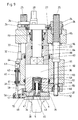
- FIGS. 7 and 8 Another modification of the exemplary embodiment shown in FIGS. 1 to 6 is shown in FIGS. 7 and 8, only the modification being described here and reference being made to the description of the first exemplary embodiment.
- a spindle 70 engaging in the center of the respective support 6 is provided, which is provided with a support bearing disk 71 and is seated in a bearing bore 72 in which it is supported by a bearing cover 73 is rotatably but axially fixed.
- the spindle 70 engages in a nut thread inside a bevel gear 75 which is in engagement with a second bevel gear 76 which is connected to a shaft 77.
- Both bevel gears 75 and 76 and the shaft 77 are mounted in a gear housing 78 which is fastened to the tappet 12 so that the gear housing 78 together with the bevel gears 75 and 76 and the shaft 77 move with the tappet 12.
- the shaft 77 engages with a splined shaft 79 in a hollow shaft 80 with a splined bore, so it is connected to it in a longitudinally displaceable but non-rotatable manner.
- the hollow shaft 80 is mounted on the frame 1 in bearings 81 and 82, and is driven by a swivel motor 83 which, like each swivel motor 63 in the exemplary embodiment according to FIGS. 1 to 6, is connected to a rotary encoder 84.
- the plunger 92 is designed as a piston which is in a fixed with the Frame 91 connected cylinder 93 is guided and acted upon.
- the stroke position is adjusted here by adjusting a plug 94 which replaces the cylinder base and which is supported on a crossmember 95 which, like the crossmember 16 in the exemplary embodiment according to FIGS. 1 to 6, is supported on the frame 1 and is adjustable relative to the frame 1.
- Fastening and transverse adjustment of the tool 5 is also the same as that in the exemplary embodiment according to FIGS. 1 to 6. Reference is made to the relevant description of FIGS. 1 to 6.
- a piston shaft 96 with a square shoulder 97 is guided in a square bore 98, the piston shaft 96 also being connected to an annular piston 99 for the retraction of the piston or plunger 92.
Landscapes
- Engineering & Computer Science (AREA)
- Mechanical Engineering (AREA)
- Forging (AREA)
- Disintegrating Or Milling (AREA)
Claims (3)
- Machine à forger comprenant quatre coulisseaux portant des outils, disposés en X dans un même plan, décalés de 90° les uns par rapport aux autres, et qui agissent radialement sur la pièce que l'on fait passer longitudinalement dans l'axe du système, dans laquelle les coulisseaux (2 ; 92) guidés dans le bâti (1) de la machine constituent des parties d'unités piston-cylindre (15, 12 ; 92, 93, 94) possédant une course qui correspond à la course de travail du coulisseau (2 ; 92), et peuvent être réglés dans leur position de course par des traverses (16 ; 95) réglables par rapport au bâti (1) de la machine et qui prennent appui sur les unités à piston-cylindre (15, 12 ; 92, 93, 94) et dans laquelle les outils (5), qui peuvent se déplacer transversalement sur les coulisseaux (2 ; 92) , dans leur plan commun, sous l'action de supports d'outils (6), peuvent être réglés et immobilisés par des actionneurs (54 à 63 ; 70 à 83) qui sont entraînés par l'intermédiaire d'arbres (58 ; 77) placés extérieurement à côté des coulisseaux (2 ; 92) et dont les organes finaux (54 ; 70) sont reliés aux supports (6), en fonction du réglage de la position de fin de course des coulisseaux (2 ; 92), de manière que les outils (5) qui sont recouverts, sur la partie de leur surface de travail qui déborde au-delà du calibre, par une surface latérale d'un outil voisin (5), forment un calibre fermé dans leur position de fin de course,
caractérisée
en ce que les transmissions (54 à 58 ; 70 et 77) des actionneurs (54 à 63 ; 70 à 83) sont reliés aux coulisseaux (2 ; 92) et à leurs entraînements (63 ; 83) par l'intermédiaire de joints tournants (59, 60 ; 79, 80) qui compensent le mouvement des coulisseaux. - Machine à forger selon la revendication 1,
caractérisée
en ce que les entraînements (63 ; 83) des actionneurs (52 à 63 ; 70 à 83) sont fixés au bâti (1) de la machine et les joints tournants (59, 60 ; 79, 80) attaquant les transmissions (54 à 58 ; 70 à 77) sont dimensionnés pour pouvoir assurer la compensation de la course de travail et du réglage de la position de course des coulisseaux (2 ; 92). - Machine à forger selon la revendication 2,
caractérisée
en ce qu'il est prévu comme entraînements, des moteurs oscillants hydrauliques (63 ; 83) munis de pignons qui sont entraînés en rotation par des pistons par l'intermédiaire de crémaillères, dont les pignons sont reliés, d'une part, par des arbres télescopiques (59, 60 ; 79, 80) aux transmissions (54 à 68 ; 70 à 77) des actionneurs (54 à 63 ; 70 à 83) et, d'autre part, à des capteurs de rotation (64 ; 84) qui captent la course de réglage.
Priority Applications (3)
| Application Number | Priority Date | Filing Date | Title |
|---|---|---|---|
| DE91122359T DE59100510D1 (de) | 1991-12-30 | 1991-12-30 | Schmiedemaschine. |
| EP91122359A EP0549825B1 (fr) | 1991-12-30 | 1991-12-30 | Machine à forger |
| AT91122359T ATE96064T1 (de) | 1991-12-30 | 1991-12-30 | Schmiedemaschine. |
Applications Claiming Priority (1)
| Application Number | Priority Date | Filing Date | Title |
|---|---|---|---|
| EP91122359A EP0549825B1 (fr) | 1991-12-30 | 1991-12-30 | Machine à forger |
Publications (2)
| Publication Number | Publication Date |
|---|---|
| EP0549825A1 EP0549825A1 (fr) | 1993-07-07 |
| EP0549825B1 true EP0549825B1 (fr) | 1993-10-20 |
Family
ID=8207483
Family Applications (1)
| Application Number | Title | Priority Date | Filing Date |
|---|---|---|---|
| EP91122359A Expired - Lifetime EP0549825B1 (fr) | 1991-12-30 | 1991-12-30 | Machine à forger |
Country Status (3)
| Country | Link |
|---|---|
| EP (1) | EP0549825B1 (fr) |
| AT (1) | ATE96064T1 (fr) |
| DE (1) | DE59100510D1 (fr) |
Families Citing this family (4)
| Publication number | Priority date | Publication date | Assignee | Title |
|---|---|---|---|---|
| DE59304440D1 (de) * | 1993-12-16 | 1996-12-12 | Hasenclever Maschf Sms | Schmiedemaschine |
| DE4444493A1 (de) * | 1993-12-16 | 1995-06-22 | Hasenclever Maschf Sms | Schmiedemaschine |
| EP0653258B1 (fr) * | 1993-12-16 | 1995-05-24 | SMS HASENCLEVER GmbH | Machine à forger |
| DE102017214961B4 (de) * | 2017-03-22 | 2021-06-10 | Sms Group Gmbh | Radial-Schmiedeanlage |
Family Cites Families (3)
| Publication number | Priority date | Publication date | Assignee | Title |
|---|---|---|---|---|
| DE1908362A1 (de) * | 1969-02-20 | 1970-09-10 | Sack Gmbh Maschf | Schmiedemaschine mit verstellbaren Schmiedesaetteln |
| EP0228030B1 (fr) * | 1986-01-02 | 1991-04-24 | SMS Hasenclever GmbH | Machine de forgeage |
| DE3800220C1 (fr) * | 1988-01-07 | 1989-02-02 | Pahnke Engineering Gmbh & Co Kg, 4000 Duesseldorf, De |
-
1991
- 1991-12-30 DE DE91122359T patent/DE59100510D1/de not_active Expired - Fee Related
- 1991-12-30 EP EP91122359A patent/EP0549825B1/fr not_active Expired - Lifetime
- 1991-12-30 AT AT91122359T patent/ATE96064T1/de not_active IP Right Cessation
Also Published As
| Publication number | Publication date |
|---|---|
| EP0549825A1 (fr) | 1993-07-07 |
| DE59100510D1 (de) | 1993-11-25 |
| ATE96064T1 (de) | 1993-11-15 |
Similar Documents
| Publication | Publication Date | Title |
|---|---|---|
| EP0228030B1 (fr) | Machine de forgeage | |
| DE2944983C2 (de) | Spindelstock für eine Universal-Fräs- und Bohrmaschine | |
| EP3875215B1 (fr) | Plaque de serrage à point zéro, machine-outil pourvue d'une telle plaque de serrage et dispositif de serrage | |
| EP0260546B1 (fr) | Machine à forger | |
| DE2308984A1 (de) | Schalttisch-automat | |
| DE4020579C2 (fr) | ||
| EP0549825B1 (fr) | Machine à forger | |
| EP0228658B1 (fr) | Machine de forgeage | |
| EP0005831B1 (fr) | Dispositif à former les dentures intérieures de grandes pièces, pour mortaiseuse d'engrenages | |
| DE4143175A1 (de) | Schmiedemaschine | |
| DE2731793B2 (de) | Vorrichtung zum spanabhebenden Bearbeiten der Zahnenden an Zahnrädern | |
| EP0653258B1 (fr) | Machine à forger | |
| EP0539667B1 (fr) | Tourelle porte-outil | |
| DE4444497A1 (de) | Schmiedemaschine | |
| EP0659501B1 (fr) | Machine à forger | |
| DE3738217C2 (de) | Schmiedemaschine | |
| DE4143176A1 (de) | Schmiedemaschine | |
| DE4444498A1 (de) | Schmiedemaschine | |
| EP0549826B1 (fr) | Machine à forger | |
| EP0260477B1 (fr) | Machine à brochage verticale | |
| EP0653257B1 (fr) | Machine à forger | |
| DE4444493A1 (de) | Schmiedemaschine | |
| DE3643116A1 (de) | Schmiedemaschine | |
| DE8623759U1 (de) | Schmiedemaschine | |
| DE8622080U1 (de) | Schmiedemaschine |
Legal Events
| Date | Code | Title | Description |
|---|---|---|---|
| PUAI | Public reference made under article 153(3) epc to a published international application that has entered the european phase |
Free format text: ORIGINAL CODE: 0009012 |
|
| 17P | Request for examination filed |
Effective date: 19920213 |
|
| AK | Designated contracting states |
Kind code of ref document: A1 Designated state(s): AT DE FR GB IT |
|
| GRAA | (expected) grant |
Free format text: ORIGINAL CODE: 0009210 |
|
| ITF | It: translation for a ep patent filed | ||
| AK | Designated contracting states |
Kind code of ref document: B1 Designated state(s): AT DE FR GB IT |
|
| REF | Corresponds to: |
Ref document number: 96064 Country of ref document: AT Date of ref document: 19931115 Kind code of ref document: T |
|
| REF | Corresponds to: |
Ref document number: 59100510 Country of ref document: DE Date of ref document: 19931125 |
|
| GBT | Gb: translation of ep patent filed (gb section 77(6)(a)/1977) |
Effective date: 19931029 |
|
| ET | Fr: translation filed | ||
| PLBE | No opposition filed within time limit |
Free format text: ORIGINAL CODE: 0009261 |
|
| STAA | Information on the status of an ep patent application or granted ep patent |
Free format text: STATUS: NO OPPOSITION FILED WITHIN TIME LIMIT |
|
| 26N | No opposition filed | ||
| PGFP | Annual fee paid to national office [announced via postgrant information from national office to epo] |
Ref country code: FR Payment date: 19951215 Year of fee payment: 5 |
|
| PGFP | Annual fee paid to national office [announced via postgrant information from national office to epo] |
Ref country code: GB Payment date: 19951221 Year of fee payment: 5 |
|
| PG25 | Lapsed in a contracting state [announced via postgrant information from national office to epo] |
Ref country code: GB Effective date: 19961230 |
|
| GBPC | Gb: european patent ceased through non-payment of renewal fee |
Effective date: 19961230 |
|
| PG25 | Lapsed in a contracting state [announced via postgrant information from national office to epo] |
Ref country code: FR Effective date: 19970829 |
|
| REG | Reference to a national code |
Ref country code: FR Ref legal event code: ST |
|
| PGFP | Annual fee paid to national office [announced via postgrant information from national office to epo] |
Ref country code: AT Payment date: 19971219 Year of fee payment: 7 |
|
| PGFP | Annual fee paid to national office [announced via postgrant information from national office to epo] |
Ref country code: DE Payment date: 19980219 Year of fee payment: 7 |
|
| PG25 | Lapsed in a contracting state [announced via postgrant information from national office to epo] |
Ref country code: AT Free format text: LAPSE BECAUSE OF NON-PAYMENT OF DUE FEES Effective date: 19981230 |
|
| PG25 | Lapsed in a contracting state [announced via postgrant information from national office to epo] |
Ref country code: DE Free format text: LAPSE BECAUSE OF NON-PAYMENT OF DUE FEES Effective date: 19991001 |
|
| PG25 | Lapsed in a contracting state [announced via postgrant information from national office to epo] |
Ref country code: IT Free format text: LAPSE BECAUSE OF NON-PAYMENT OF DUE FEES;WARNING: LAPSES OF ITALIAN PATENTS WITH EFFECTIVE DATE BEFORE 2007 MAY HAVE OCCURRED AT ANY TIME BEFORE 2007. THE CORRECT EFFECTIVE DATE MAY BE DIFFERENT FROM THE ONE RECORDED. Effective date: 20051230 |