EP0549996A1 - Valve de remise à zéro pour système de frein moteur à décompression - Google Patents
Valve de remise à zéro pour système de frein moteur à décompression Download PDFInfo
- Publication number
- EP0549996A1 EP0549996A1 EP92121780A EP92121780A EP0549996A1 EP 0549996 A1 EP0549996 A1 EP 0549996A1 EP 92121780 A EP92121780 A EP 92121780A EP 92121780 A EP92121780 A EP 92121780A EP 0549996 A1 EP0549996 A1 EP 0549996A1
- Authority
- EP
- European Patent Office
- Prior art keywords
- bore
- plunger
- slave piston
- cylinder
- apparatus defined
- Prior art date
- Legal status (The legal status is an assumption and is not a legal conclusion. Google has not performed a legal analysis and makes no representation as to the accuracy of the status listed.)
- Granted
Links
- 230000006835 compression Effects 0.000 title claims abstract description 10
- 238000007906 compression Methods 0.000 title claims abstract description 10
- 239000012530 fluid Substances 0.000 claims description 22
- 230000000670 limiting effect Effects 0.000 claims description 3
- 238000004891 communication Methods 0.000 claims description 2
- 238000004519 manufacturing process Methods 0.000 abstract description 5
- 230000007246 mechanism Effects 0.000 abstract description 5
- 230000009467 reduction Effects 0.000 abstract description 2
- 238000002485 combustion reaction Methods 0.000 description 3
- 238000006073 displacement reaction Methods 0.000 description 2
- 230000014509 gene expression Effects 0.000 description 2
- 230000000979 retarding effect Effects 0.000 description 2
- 238000001816 cooling Methods 0.000 description 1
- 230000003247 decreasing effect Effects 0.000 description 1
- 239000000446 fuel Substances 0.000 description 1
- 230000006872 improvement Effects 0.000 description 1
- 238000002347 injection Methods 0.000 description 1
- 239000007924 injection Substances 0.000 description 1
- 238000012986 modification Methods 0.000 description 1
- 230000004048 modification Effects 0.000 description 1
- 230000002829 reductive effect Effects 0.000 description 1
- 230000002441 reversible effect Effects 0.000 description 1
- 238000007789 sealing Methods 0.000 description 1
- 238000000926 separation method Methods 0.000 description 1
Images



Classifications
-
- F—MECHANICAL ENGINEERING; LIGHTING; HEATING; WEAPONS; BLASTING
- F01—MACHINES OR ENGINES IN GENERAL; ENGINE PLANTS IN GENERAL; STEAM ENGINES
- F01L—CYCLICALLY OPERATING VALVES FOR MACHINES OR ENGINES
- F01L13/00—Modifications of valve-gear to facilitate reversing, braking, starting, changing compression ratio, or other specific operations
- F01L13/06—Modifications of valve-gear to facilitate reversing, braking, starting, changing compression ratio, or other specific operations for braking
- F01L13/065—Compression release engine retarders of the "Jacobs Manufacturing" type
-
- F—MECHANICAL ENGINEERING; LIGHTING; HEATING; WEAPONS; BLASTING
- F01—MACHINES OR ENGINES IN GENERAL; ENGINE PLANTS IN GENERAL; STEAM ENGINES
- F01L—CYCLICALLY OPERATING VALVES FOR MACHINES OR ENGINES
- F01L2305/00—Valve arrangements comprising rollers
Definitions
- This invention relates to compression relief engine retarders, and more particularly to slave pistons in these systems that incorporate a clipping mechanism to limit their maximum displacement.
- Engine retarders of the compression relief type are well known in the art. In general, such retarders are designed to temporarily convert an internal combustion engine into an air compressor so as to develop a retarding horsepower which may be a substantial portion of the operating horsepower developed by the engine in its operating mode.
- a typical slave piston design incorporating such a reset mechanism uses a lash-adjusting screw containing a reciprocating plunger that makes a face fit over a hole in the slave piston surface. With this design the travel of the reciprocating plunger is arrested upon contact with a press-fit pin that fits in a slot within the body of the plunger.
- This system is relatively costly to manufacture due to the complex configurations of its various parts, the need to test it to ensure that the pin will not come out, etc.
- the lash-adjusting screw may also pose a problem if it is hollow at the point at which it is held by a housing or other mounting because it may break if tightened excessively.
- slave piston clipping apparatus It is therefore an object of the present invention to provide an improved slave piston clipping apparatus. It is a more particular object of this invention to provide slave pistons which are more robust, easier to manufacture and display rapid clipping rates.
- the plunger contains bores that equalize the hydraulic fluid pressure between the slave piston cylinder and the interior of the hollow lash adjusting screw, allowing unhindered reciprocating motion of the plunger in the screw.
- the present invention allows a reduction in the length of the hollow portion of the lash-adjusting screw.
- the invention also improves upon the older design as it eliminates the need for the press-fit pin.
- the apparatus is more robust than previous designs and is easier and cheaper to manufacture.
- slave piston 10 reciprocates in slave piston cylinder 32 along longitudinal axis 60 in housing 30.
- the initial position of slave piston 10 is determined by the adjustment of screw 70, which is held in place against housing 30 by nut 40.
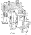
- a high pressure pulse generally in the range of 2000-4000 psi, is generated by a master piston and transmitted through a hydraulic circuit to slave piston cylinder 32 via aperture 34. As shown in FIG.
- this pulse is produced by the rotation of engine injection cam 340, which urges arm 335 to move rocker arm 325 via member 330, urging master piston 320 against the hydraulic fluid in high pressure passage 302 of the hydraulic circuit.
- the force of the pressurized hydraulic fluid against the top end face 14 of slave piston 10 causes slave piston 10 to move along longitudinal axis 60 in a downward direction so that slave piston 10 urges member 350 downward, holding open exhaust valve 312.
- Plunger 20, which reciprocates in the hollow portion of screw 70, has a slot 28 through which pin 22 is inserted. Pin 22 is press-fit into screw 70.
- the excursion of plunger 20 is determined by the location of pin 22 between the top 24 and the bottom 26 of slot 28.
- plunger 20 is held against aperture 12 of slave piston 10 by spring 50 so as to block the escape of hydraulic fluid until the top 24 of slot 28 comes into contact with pin 22.
- Spring 50 has sufficient strength to hold the flat lower end face of plunger 20 against the flat upper surface 14 of slave piston 10, forming a "face fit" between the two end faces.
- slave piston 10 When top 24 of slot 28 contacts pin 22, slave piston 10 separates from plunger 20. This allows hydraulic fluid to escape from slave piston cylinder 32 through aperture 12 in slave piston 10, thereby automatically limiting the downward travel of slave piston 10 and the amount by which the associated exhaust valve is opened. When the master piston no longer applies the high pressure pulse, slave piston 10 is driven back up to its initial position by spring 352.
- FIGS. 4-6 The components of the clip valve assembly 301 of the present invention are shown in FIGS. 4-6. They include: clip valve body screw 100, spring 200, retaining ring 300 and plunger 400.
- the clip valve body is threaded with threads 110, to allow adjustment of the lash in the system, and has a longitudinal bore 120, to accept plunger 400 for reciprocation within.
- the body also has groove 140 in the interior of bore 120, for seating retaining ring 300.
- Retaining ring 300 is initially split at one point along its circumference, and has an outer diameter larger than that of groove 140. During assembly spring 200 and plunger 400 are inserted in bore 120.
- ring 300 is annularly compressed, decreasing its diameter to less than that of bore 120, and fit within groove 140. Retaining ring 300 is then released, expanding to fit firmly in groove 140.
- Plunger 400 contains two bores: axial bore 410, and transverse bore 420, which is connected to bore 410 via aperture 424.
- the clip valve assembly is mounted on a housing 910, as shown in FIG. 6, which includes slave piston cylinder 800. Additionally, screw 100 may be fastened to housing 910 with a lock-nut 920.
- Slave piston 700 reciprocates in slave piston cylinder 800 in a direction substantially parallel to longitudinal axis 500. Slave piston 700 and plunger 400 are initially in a position where slave piston return spring 352 has urged slave piston 700 toward clip valve plunger 400, overcoming weaker spring 200. In this position, upper surface 720 of slave piston 700 is in contact with lower surface 450 of plunger 400, sealing hole 710 closed.
- the pressure in regions 125 and 810 are further equalized by the passage of hydraulic fluid between exterior wall 402 of plunger 400 and bore 120, and the passage of fluid around retaining ring 300 via slot 130.
- plunger 400 reaches the end of its travel, as determined by the contact of external annular shoulder surface 440 of plunger 400 with the upper surface 310 of retaining ring 300, the lower surface 450 of plunger 400 and the upper surface 720 of slave piston 700 separate. This separation allows the escape of high pressure hydraulic fluid from upper region 810 of slave piston cylinder 800 via hole 710 into low pressure region 730 of slave piston 700.
- slave piston 700 is driven back up to its initial position by a spring (not shown).
- the present invention overcomes the need for pin 22 while additionally reducing the extent of the hollow portion of the screw.
- the apparatus is also more robust than previous designs and is easier and cheaper to manufacture.
Landscapes
- Engineering & Computer Science (AREA)
- Mechanical Engineering (AREA)
- General Engineering & Computer Science (AREA)
- Valve Device For Special Equipments (AREA)
- Output Control And Ontrol Of Special Type Engine (AREA)
Applications Claiming Priority (2)
| Application Number | Priority Date | Filing Date | Title |
|---|---|---|---|
| US816662 | 1992-01-03 | ||
| US07/816,662 US5201290A (en) | 1992-01-03 | 1992-01-03 | Compression relief engine retarder clip valve |
Publications (2)
| Publication Number | Publication Date |
|---|---|
| EP0549996A1 true EP0549996A1 (fr) | 1993-07-07 |
| EP0549996B1 EP0549996B1 (fr) | 1996-09-11 |
Family
ID=25221296
Family Applications (1)
| Application Number | Title | Priority Date | Filing Date |
|---|---|---|---|
| EP92121780A Expired - Lifetime EP0549996B1 (fr) | 1992-01-03 | 1992-12-22 | Valve de remise à zéro pour système de frein moteur à décompression |
Country Status (6)
| Country | Link |
|---|---|
| US (1) | US5201290A (fr) |
| EP (1) | EP0549996B1 (fr) |
| JP (1) | JPH06207539A (fr) |
| CA (1) | CA2085935A1 (fr) |
| DE (1) | DE69213697T2 (fr) |
| MX (1) | MX9207670A (fr) |
Cited By (1)
| Publication number | Priority date | Publication date | Assignee | Title |
|---|---|---|---|---|
| EP1219792A3 (fr) * | 2000-12-19 | 2003-03-05 | Caterpillar Inc. | Actionneur de soupape avec dispositif de rattrapage de jeu |
Families Citing this family (24)
| Publication number | Priority date | Publication date | Assignee | Title |
|---|---|---|---|---|
| DE4121435C2 (de) * | 1991-06-28 | 1995-10-12 | Rexroth Mannesmann Gmbh | Motorbremse für eine mehrzylindrige Brennkraftmaschine |
| US5361740A (en) * | 1993-03-29 | 1994-11-08 | Jacobs Brake Technology Corporation | Mechanical assemblies with hardened bearing surfaces |
| US5379737A (en) * | 1993-08-26 | 1995-01-10 | Jacobs Brake Technology Corporation | Electrically controlled timing adjustment for compression release engine brakes |
| US5540201A (en) | 1994-07-29 | 1996-07-30 | Caterpillar Inc. | Engine compression braking apparatus and method |
| US5647318A (en) | 1994-07-29 | 1997-07-15 | Caterpillar Inc. | Engine compression braking apparatus and method |
| US5526784A (en) | 1994-08-04 | 1996-06-18 | Caterpillar Inc. | Simultaneous exhaust valve opening braking system |
| US5462025A (en) * | 1994-09-28 | 1995-10-31 | Diesel Engine Retarders, Inc. | Hydraulic circuits for compression release engine brakes |
| US5511460A (en) * | 1995-01-25 | 1996-04-30 | Diesel Engine Retarders, Inc. | Stroke limiter for hydraulic actuator pistons in compression release engine brakes |
| US5507261A (en) * | 1995-05-12 | 1996-04-16 | Caterpillar Inc. | Four cycle engine with two cycle compression braking system |
| US5495838A (en) * | 1995-05-12 | 1996-03-05 | Caterpillar Inc. | Compression braking system |
| US5809964A (en) * | 1997-02-03 | 1998-09-22 | Diesel Engine Retarders, Inc. | Method and apparatus to accomplish exhaust air recirculation during engine braking and/or exhaust gas recirculation during positive power operation of an internal combustion engine |
| US5758620A (en) * | 1997-03-21 | 1998-06-02 | Detroit Diesel Corporation | Engine compression brake system |
| US5996550A (en) * | 1997-07-14 | 1999-12-07 | Diesel Engine Retarders, Inc. | Applied lost motion for optimization of fixed timed engine brake system |
| US8820276B2 (en) | 1997-12-11 | 2014-09-02 | Jacobs Vehicle Systems, Inc. | Variable lost motion valve actuator and method |
| US6095115A (en) * | 1998-02-02 | 2000-08-01 | Diesel Engine Retarders, Inc. | Self-clipping slave piston device with lash adjustment for a compression release engine retarder |
| US6273057B1 (en) | 1998-08-19 | 2001-08-14 | Diesel Engine Retarders, Inc. | Hydraulically-actuated fail-safe stroke-limiting piston |
| ATE454536T1 (de) * | 1999-09-16 | 2010-01-15 | Diesel Engine Retarders Inc | Verfahren und vorrichtung zur kontrolle der ventilschliessgeschwindigkeit |
| DE60045108D1 (de) * | 1999-12-20 | 2010-11-25 | Jacobs Vehicle Systems Inc | Verfahren und vorrichtung zum hydraulischen an- und loskoppeln einer motorbremse mittels totgang |
| US6691674B2 (en) | 2001-06-13 | 2004-02-17 | Diesel Engine Retarders, Inc. | Latched reset mechanism for engine brake |
| US6971366B2 (en) | 2001-11-30 | 2005-12-06 | Caterpillar Inc. | Integral lash adjustor for hydraulic compression engine brake |
| US6626137B2 (en) | 2002-01-14 | 2003-09-30 | Caterpillar Inc | Automatic lash adjuster |
| US20040083994A1 (en) * | 2002-10-30 | 2004-05-06 | Homa Afjeh | System for actuating an engine valve |
| JP5617274B2 (ja) * | 2010-02-19 | 2014-11-05 | いすゞ自動車株式会社 | 可変バルブタイミング機構 |
| KR20180008556A (ko) | 2015-05-18 | 2018-01-24 | 이턴 에스알엘 | 어큐뮬레이터로서 작동하는 오일 배출 밸브를 갖는 로커 암 |
Citations (5)
| Publication number | Priority date | Publication date | Assignee | Title |
|---|---|---|---|---|
| US3405699A (en) * | 1966-06-17 | 1968-10-15 | Jacobs Mfg Co | Engine braking system with trip valve controlled piston |
| EP0083058A1 (fr) * | 1981-12-24 | 1983-07-06 | The Jacobs Manufacturing Company | Système de frein moteur du type à détente de gaz comprimé |
| US4423712A (en) * | 1982-04-28 | 1984-01-03 | The Jacobs Mfg. Company | Engine retarder slave piston return mechanism |
| US4742806A (en) * | 1986-09-10 | 1988-05-10 | Tart Jr Earl D | Auxiliary engine braking system |
| US5036810A (en) * | 1990-08-07 | 1991-08-06 | Jenara Enterprises Ltd. | Engine brake and method |
Family Cites Families (3)
| Publication number | Priority date | Publication date | Assignee | Title |
|---|---|---|---|---|
| US3220392A (en) * | 1962-06-04 | 1965-11-30 | Clessie L Cummins | Vehicle engine braking and fuel control system |
| US4706625A (en) * | 1986-08-15 | 1987-11-17 | The Jacobs Manufacturing Company | Engine retarder with reset auto-lash mechanism |
| US4898128A (en) * | 1988-04-07 | 1990-02-06 | Meneely Vincent A | Anti-lash adjuster |
-
1992
- 1992-01-03 US US07/816,662 patent/US5201290A/en not_active Expired - Lifetime
- 1992-12-21 CA CA002085935A patent/CA2085935A1/fr not_active Abandoned
- 1992-12-22 EP EP92121780A patent/EP0549996B1/fr not_active Expired - Lifetime
- 1992-12-22 DE DE69213697T patent/DE69213697T2/de not_active Expired - Fee Related
- 1992-12-30 MX MX9207670A patent/MX9207670A/es unknown
-
1993
- 1993-01-04 JP JP5014396A patent/JPH06207539A/ja active Pending
Patent Citations (5)
| Publication number | Priority date | Publication date | Assignee | Title |
|---|---|---|---|---|
| US3405699A (en) * | 1966-06-17 | 1968-10-15 | Jacobs Mfg Co | Engine braking system with trip valve controlled piston |
| EP0083058A1 (fr) * | 1981-12-24 | 1983-07-06 | The Jacobs Manufacturing Company | Système de frein moteur du type à détente de gaz comprimé |
| US4423712A (en) * | 1982-04-28 | 1984-01-03 | The Jacobs Mfg. Company | Engine retarder slave piston return mechanism |
| US4742806A (en) * | 1986-09-10 | 1988-05-10 | Tart Jr Earl D | Auxiliary engine braking system |
| US5036810A (en) * | 1990-08-07 | 1991-08-06 | Jenara Enterprises Ltd. | Engine brake and method |
Cited By (1)
| Publication number | Priority date | Publication date | Assignee | Title |
|---|---|---|---|---|
| EP1219792A3 (fr) * | 2000-12-19 | 2003-03-05 | Caterpillar Inc. | Actionneur de soupape avec dispositif de rattrapage de jeu |
Also Published As
| Publication number | Publication date |
|---|---|
| DE69213697T2 (de) | 1997-01-23 |
| DE69213697D1 (de) | 1996-10-17 |
| JPH06207539A (ja) | 1994-07-26 |
| US5201290A (en) | 1993-04-13 |
| EP0549996B1 (fr) | 1996-09-11 |
| CA2085935A1 (fr) | 1993-07-04 |
| MX9207670A (es) | 1994-05-31 |
Similar Documents
| Publication | Publication Date | Title |
|---|---|---|
| US5201290A (en) | Compression relief engine retarder clip valve | |
| US5161501A (en) | Self-clippping slave piston | |
| EP0083058B1 (fr) | Système de frein moteur du type à détente de gaz comprimé | |
| US5000145A (en) | Compression release retarding system | |
| US6439195B1 (en) | Valve train apparatus | |
| US5460131A (en) | Compact combined lash adjuster and reset mechanism for compression release engine brakes | |
| US4706625A (en) | Engine retarder with reset auto-lash mechanism | |
| EP0828061A1 (fr) | Méthode de freinage moteur par compression renforcée par les pulsations de gaz d'échappement | |
| GB2253882A (en) | Hydraulic high-pressure pump for motor vehicle brake systems | |
| US5711279A (en) | Fuel system | |
| EP1734252A3 (fr) | Pompe à combustible haute pression pour moteurs à combustion interne | |
| US4419977A (en) | Fuel injection system and timing advance device therefor | |
| US5511460A (en) | Stroke limiter for hydraulic actuator pistons in compression release engine brakes | |
| EP0365130A1 (fr) | Tuyère d'injection de combustible | |
| EP1218635B1 (fr) | Piston d'avance d'injection pour pompe d'injection de carburant | |
| US4254749A (en) | Fuel injection system and timing advance device therefor | |
| US4898206A (en) | Compression release retarder with valve motion modifier | |
| EP0985805A3 (fr) | Dispositif hydraulique de ratrapage de jeu aux soupapes | |
| US6095115A (en) | Self-clipping slave piston device with lash adjustment for a compression release engine retarder | |
| US4838516A (en) | Compression release retarder with valve motion modifier | |
| US4949751A (en) | Compression release retarder with valve motion modifier | |
| JPH0579804B2 (fr) | ||
| JPH04287812A (ja) | 内燃機関用機関弁の油圧駆動装置 |
Legal Events
| Date | Code | Title | Description |
|---|---|---|---|
| PUAI | Public reference made under article 153(3) epc to a published international application that has entered the european phase |
Free format text: ORIGINAL CODE: 0009012 |
|
| AK | Designated contracting states |
Kind code of ref document: A1 Designated state(s): DE GB SE |
|
| 17P | Request for examination filed |
Effective date: 19931210 |
|
| 17Q | First examination report despatched |
Effective date: 19941121 |
|
| GRAG | Despatch of communication of intention to grant |
Free format text: ORIGINAL CODE: EPIDOS AGRA |
|
| GRAH | Despatch of communication of intention to grant a patent |
Free format text: ORIGINAL CODE: EPIDOS IGRA |
|
| GRAH | Despatch of communication of intention to grant a patent |
Free format text: ORIGINAL CODE: EPIDOS IGRA |
|
| GRAA | (expected) grant |
Free format text: ORIGINAL CODE: 0009210 |
|
| AK | Designated contracting states |
Kind code of ref document: B1 Designated state(s): DE GB SE |
|
| REF | Corresponds to: |
Ref document number: 69213697 Country of ref document: DE Date of ref document: 19961017 |
|
| PLBE | No opposition filed within time limit |
Free format text: ORIGINAL CODE: 0009261 |
|
| STAA | Information on the status of an ep patent application or granted ep patent |
Free format text: STATUS: NO OPPOSITION FILED WITHIN TIME LIMIT |
|
| 26N | No opposition filed | ||
| REG | Reference to a national code |
Ref country code: GB Ref legal event code: IF02 |
|
| PGFP | Annual fee paid to national office [announced via postgrant information from national office to epo] |
Ref country code: GB Payment date: 20031217 Year of fee payment: 12 |
|
| PGFP | Annual fee paid to national office [announced via postgrant information from national office to epo] |
Ref country code: SE Payment date: 20031219 Year of fee payment: 12 |
|
| PGFP | Annual fee paid to national office [announced via postgrant information from national office to epo] |
Ref country code: DE Payment date: 20040202 Year of fee payment: 12 |
|
| PG25 | Lapsed in a contracting state [announced via postgrant information from national office to epo] |
Ref country code: GB Free format text: LAPSE BECAUSE OF NON-PAYMENT OF DUE FEES Effective date: 20041222 |
|
| PG25 | Lapsed in a contracting state [announced via postgrant information from national office to epo] |
Ref country code: SE Free format text: LAPSE BECAUSE OF NON-PAYMENT OF DUE FEES Effective date: 20041223 |
|
| PG25 | Lapsed in a contracting state [announced via postgrant information from national office to epo] |
Ref country code: DE Free format text: LAPSE BECAUSE OF NON-PAYMENT OF DUE FEES Effective date: 20050701 |
|
| EUG | Se: european patent has lapsed | ||
| GBPC | Gb: european patent ceased through non-payment of renewal fee |
Effective date: 20041222 |