EP0549997A1 - Selbstbegrenzungs-Slavekolben - Google Patents
Selbstbegrenzungs-Slavekolben Download PDFInfo
- Publication number
- EP0549997A1 EP0549997A1 EP92121781A EP92121781A EP0549997A1 EP 0549997 A1 EP0549997 A1 EP 0549997A1 EP 92121781 A EP92121781 A EP 92121781A EP 92121781 A EP92121781 A EP 92121781A EP 0549997 A1 EP0549997 A1 EP 0549997A1
- Authority
- EP
- European Patent Office
- Prior art keywords
- slave piston
- bore
- cylinder
- valve member
- longitudinal axis
- Prior art date
- Legal status (The legal status is an assumption and is not a legal conclusion. Google has not performed a legal analysis and makes no representation as to the accuracy of the status listed.)
- Granted
Links
- 239000012530 fluid Substances 0.000 claims abstract description 21
- 230000006835 compression Effects 0.000 claims abstract description 7
- 238000007906 compression Methods 0.000 claims abstract description 7
- 239000007787 solid Substances 0.000 claims description 3
- 230000007246 mechanism Effects 0.000 abstract description 6
- 238000006073 displacement reaction Methods 0.000 abstract description 3
- 238000004519 manufacturing process Methods 0.000 abstract description 3
- 238000011084 recovery Methods 0.000 description 3
- 238000002485 combustion reaction Methods 0.000 description 2
- 230000014509 gene expression Effects 0.000 description 2
- 230000000979 retarding effect Effects 0.000 description 2
- 238000001816 cooling Methods 0.000 description 1
- 230000008030 elimination Effects 0.000 description 1
- 238000003379 elimination reaction Methods 0.000 description 1
- 239000000446 fuel Substances 0.000 description 1
- 238000002347 injection Methods 0.000 description 1
- 239000007924 injection Substances 0.000 description 1
- 238000012986 modification Methods 0.000 description 1
- 230000004048 modification Effects 0.000 description 1
Images


Classifications
-
- F—MECHANICAL ENGINEERING; LIGHTING; HEATING; WEAPONS; BLASTING
- F01—MACHINES OR ENGINES IN GENERAL; ENGINE PLANTS IN GENERAL; STEAM ENGINES
- F01L—CYCLICALLY OPERATING VALVES FOR MACHINES OR ENGINES
- F01L13/00—Modifications of valve-gear to facilitate reversing, braking, starting, changing compression ratio, or other specific operations
- F01L13/06—Modifications of valve-gear to facilitate reversing, braking, starting, changing compression ratio, or other specific operations for braking
- F01L13/065—Compression release engine retarders of the "Jacobs Manufacturing" type
-
- F—MECHANICAL ENGINEERING; LIGHTING; HEATING; WEAPONS; BLASTING
- F01—MACHINES OR ENGINES IN GENERAL; ENGINE PLANTS IN GENERAL; STEAM ENGINES
- F01L—CYCLICALLY OPERATING VALVES FOR MACHINES OR ENGINES
- F01L2305/00—Valve arrangements comprising rollers
Definitions
- This invention relates to compression relief engine retarders, and more particularly to slave pistons in these systems that incorporate a clipping mechanism to limit their maximum displacement.
- Engine retarders of the compression relief type are well known in the art. In general, such retarders are designed temporarily to convert an internal combustion engine into an air compressor so as to develop a retarding horsepower which may be a substantial portion of the operating horsepower developed by the engine in its operating mode.
- a typical slave piston design incorporating such a reset mechanism uses a hollow lash-adjusting screw containing a reciprocating plunger that makes a face fit over a hole in the slave piston surface. With this design the travel of the reciprocating plunger is arrested upon contact with a press-fit pin that fits in a slot within the body of the plunger.
- This system is relatively costly to manufacture due to the complex configurations of its various parts, the need to test it to ensure that the pin will not come out, etc.
- the hollow lash-adjusting screw is also a problem because it may break if tightened excessively.
- slave piston clipping apparatus It is therefore an object of the present invention to provide an improved slave piston clipping apparatus. It is a more particular object of this invention to provide slave pistons which are more robust, easier to manufacture and display rapid clipping rates.
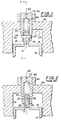
- slave piston 10 reciprocates in slave piston cylinder 32 along longitudinal axis 60 in housing 30.
- the initial position of slave piston 10 is determined by the adjustment of screw 70, which is held in place against housing 30 by nut 40.
- the overall operation of the general type of compression relief engine retarder system that uses the present invention is further shown in FIG. 3.
- a high pressure pulse generally in the range of 2000-4000 psi, is generated by the rotation of engine injection cam 340, which urges arm 335 to move rocker arm 325 via member 330, urging master piston 320 against the hydraulic fluid in high pressure passage 302 of a hydraulic circuit. This pulse is transmitted through the hydraulic circuit to slave piston cylinder 32 via aperture 34.
- slave piston 10 When top 24 of slot 28 contacts pin 22, slave piston 10 separates from plunger 20. This allows hydraulic fluid to escape from slave piston cylinder 32 through aperture 12 in slave piston 10 and via low pressure passage 304 into recovery area 360, thereby automatically limiting the downward travel of slave piston 10 and the amount by which the associated exhaust valve is opened. When the master piston no longer applies the high pressure pulse, slave piston 10 is driven back up to its initial position by spring 352 via member 350.
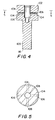
- slave piston 100 reciprocates along longitudinal axis 180 within slave piston cylinder 114, contained in housing 210.
- slave piston 100 Within slave piston 100 are bores 106 and 108, connected via aperture 112.
- Valve member 120 which is held in place against the lower end face 134 of screw 130 by spring 140, reciprocates in bore 108 along longitudinal axis 180.
- Valve member 120 makes a "lap fit" along wall 110 of bore 108 with slave piston 100.
- the slave piston system also incorporates retaining ring 170, which is used to contain valve member 120 and spring 140 within bore 108 during assembly.
- the initial position of lower end face 116 of slave piston 100 with respect to the exhaust valve (not shown) that is acted upon by slave piston 100 is determined by the adjustment of lash-adjusting screw 130 and fixed by tightening nut 200. Note that hydraulic fluid in the upper region 115 of slave piston cylinder 114 flows into bore 108 both above valve member 120 and below it via slot 123 in screw 130 and via aperture 124 in valve member 120.
- the self-clipping slave piston operates as follows: at the beginning of a cycle, when source 220 supplies relatively low pressure hydraulic fluid, the position of the elements is as shown in FIG. 6. Slave piston 100 is urged upwards against lower portion 132 of screw 130 by spring 192, which acts against support member 190. A high pressure hydraulic fluid pulse is produced by variable pressure source 220. Typically this pulse is produced as was shown in FIG. 3. The pulse is transmitted via passage 150 into upper region 115 of slave piston cylinder 114 where the resulting pressure against top end face 102 of slave piston 100 forces it in a downward direction.
- valve member 120 remains in contact with the lower surface 134 of screw 130. Accordingly, the lower edge 126 of valve member 120 eventually uncovers aperture 112, which connects bore 108 with bores 106.
- Circumferential groove 104 in slave piston 100 and aperture 162 in housing 210 are prearranged, so that they are aligned at the same time or prior to the uncovering of aperture 112 by valve member 120.
- high pressure hydraulic fluid can escape from bore 108 via the one of bores 106 that is aligned with passage way 160, circumferential groove 104, and passageway 160.
- Passageway 160 is connected to a low pressure hydraulic fluid recovery area (similar to recovery area 360, shown in FIG. 3).
- a low pressure hydraulic fluid recovery area similar to recovery area 360, shown in FIG. 3.
- the present invention overcomes the need for pin 22 while additionally providing a better lap-fit seal.
- the prior art hollow lash-adjusting screw 70 has been replaced in the current invention by solid screw 130.
Landscapes
- Engineering & Computer Science (AREA)
- Mechanical Engineering (AREA)
- General Engineering & Computer Science (AREA)
- Output Control And Ontrol Of Special Type Engine (AREA)
- Valve Device For Special Equipments (AREA)
- Pistons, Piston Rings, And Cylinders (AREA)
- Braking Arrangements (AREA)
Applications Claiming Priority (2)
| Application Number | Priority Date | Filing Date | Title |
|---|---|---|---|
| US07/816,665 US5161501A (en) | 1992-01-03 | 1992-01-03 | Self-clippping slave piston |
| US816665 | 2001-03-23 |
Publications (2)
| Publication Number | Publication Date |
|---|---|
| EP0549997A1 true EP0549997A1 (de) | 1993-07-07 |
| EP0549997B1 EP0549997B1 (de) | 1996-04-24 |
Family
ID=25221307
Family Applications (1)
| Application Number | Title | Priority Date | Filing Date |
|---|---|---|---|
| EP92121781A Expired - Lifetime EP0549997B1 (de) | 1992-01-03 | 1992-12-22 | Selbstbegrenzungs-Slavekolben |
Country Status (6)
| Country | Link |
|---|---|
| US (1) | US5161501A (de) |
| EP (1) | EP0549997B1 (de) |
| JP (1) | JPH0742520A (de) |
| CA (1) | CA2085934A1 (de) |
| DE (1) | DE69210194T2 (de) |
| MX (1) | MX9207668A (de) |
Cited By (2)
| Publication number | Priority date | Publication date | Assignee | Title |
|---|---|---|---|---|
| WO1996010125A1 (en) * | 1994-09-28 | 1996-04-04 | Diesel Engine Retarders, Inc. | Hydraulic circuits for compression release engine brakes |
| EP1009921A4 (de) * | 1997-07-14 | 2000-07-19 | Diesel Engine Retarders Inc | Optimierung durch totgang in ein motorbremssystem mit festeinstellung |
Families Citing this family (21)
| Publication number | Priority date | Publication date | Assignee | Title |
|---|---|---|---|---|
| US5347968A (en) * | 1993-05-24 | 1994-09-20 | Caterpillar Inc. | Integral air compression system |
| US5357926A (en) * | 1993-08-26 | 1994-10-25 | Jacobs Brake Technology Corporation | Compression release engine brake with selectively reduced engine exhaust noise |
| US5540201A (en) | 1994-07-29 | 1996-07-30 | Caterpillar Inc. | Engine compression braking apparatus and method |
| US5619963A (en) * | 1994-07-29 | 1997-04-15 | Caterpillar Inc. | Dual force actuator for use in engine retarding systems |
| US5647318A (en) | 1994-07-29 | 1997-07-15 | Caterpillar Inc. | Engine compression braking apparatus and method |
| US5595158A (en) * | 1994-07-29 | 1997-01-21 | Caterpillar Inc. | Dynamic positioning device for an engine brake control |
| US5526784A (en) | 1994-08-04 | 1996-06-18 | Caterpillar Inc. | Simultaneous exhaust valve opening braking system |
| US5460131A (en) * | 1994-09-28 | 1995-10-24 | Diesel Engine Retarders, Inc. | Compact combined lash adjuster and reset mechanism for compression release engine brakes |
| US5511460A (en) * | 1995-01-25 | 1996-04-30 | Diesel Engine Retarders, Inc. | Stroke limiter for hydraulic actuator pistons in compression release engine brakes |
| US5809964A (en) * | 1997-02-03 | 1998-09-22 | Diesel Engine Retarders, Inc. | Method and apparatus to accomplish exhaust air recirculation during engine braking and/or exhaust gas recirculation during positive power operation of an internal combustion engine |
| EP1023532A1 (de) | 1997-10-15 | 2000-08-02 | Diesel Engine Retarders, Inc. | Nebenkolbenanordnung mit vorrichtung zum modifizieren der ventilbewegung |
| US8820276B2 (en) * | 1997-12-11 | 2014-09-02 | Jacobs Vehicle Systems, Inc. | Variable lost motion valve actuator and method |
| US6095115A (en) * | 1998-02-02 | 2000-08-01 | Diesel Engine Retarders, Inc. | Self-clipping slave piston device with lash adjustment for a compression release engine retarder |
| US6085721A (en) * | 1998-04-03 | 2000-07-11 | Diesel Engine Retarders, Inc. | Bar engine brake |
| WO2000011336A1 (en) | 1998-08-19 | 2000-03-02 | Diesel Engine Retarders, Inc. | Hydraulically-actuated fail-safe stroke-limiting piston |
| US6405707B1 (en) * | 2000-12-18 | 2002-06-18 | Caterpillar Inc. | Integral engine and engine compression braking HEUI injector |
| US6957634B2 (en) * | 2002-10-04 | 2005-10-25 | Caterpillar Inc. | Engine valve actuator |
| US6708656B1 (en) | 2002-12-19 | 2004-03-23 | Caterpillar Inc | Engine valve actuator |
| US6997148B1 (en) | 2004-10-15 | 2006-02-14 | Caterpillar Inc. | Engine valve actuator |
| KR101290347B1 (ko) * | 2011-08-30 | 2013-07-26 | 현대제철 주식회사 | 환원시간에 따른 고로 내 환원분화 추정 방법 |
| US9200541B2 (en) * | 2012-07-20 | 2015-12-01 | Jacobs Vehicle Systems, Inc. | Systems and methods for hydraulic lash adjustment in an internal combustion engine |
Citations (2)
| Publication number | Priority date | Publication date | Assignee | Title |
|---|---|---|---|---|
| US3547087A (en) * | 1968-08-09 | 1970-12-15 | White Motor Corp | Engine valve control for braking operation |
| US5000145A (en) * | 1989-12-05 | 1991-03-19 | Quenneville Raymond N | Compression release retarding system |
Family Cites Families (10)
| Publication number | Priority date | Publication date | Assignee | Title |
|---|---|---|---|---|
| US2847261A (en) * | 1956-07-19 | 1958-08-12 | Richard T Cornelius | Piston construction |
| US3220392A (en) * | 1962-06-04 | 1965-11-30 | Clessie L Cummins | Vehicle engine braking and fuel control system |
| US3405699A (en) * | 1966-06-17 | 1968-10-15 | Jacobs Mfg Co | Engine braking system with trip valve controlled piston |
| US4381179A (en) * | 1980-10-31 | 1983-04-26 | Lear Siegler, Inc. | Pumps with floating wrist pins |
| US4399787A (en) * | 1981-12-24 | 1983-08-23 | The Jacobs Manufacturing Company | Engine retarder hydraulic reset mechanism |
| US4423712A (en) * | 1982-04-28 | 1984-01-03 | The Jacobs Mfg. Company | Engine retarder slave piston return mechanism |
| US4592319A (en) * | 1985-08-09 | 1986-06-03 | The Jacobs Manufacturing Company | Engine retarding method and apparatus |
| US4742806A (en) * | 1986-09-10 | 1988-05-10 | Tart Jr Earl D | Auxiliary engine braking system |
| US4741307A (en) * | 1987-02-17 | 1988-05-03 | Pacific Diesel Brave Co. | Apparatus and method for compression release retarding of an engine |
| US5036810A (en) * | 1990-08-07 | 1991-08-06 | Jenara Enterprises Ltd. | Engine brake and method |
-
1992
- 1992-01-03 US US07/816,665 patent/US5161501A/en not_active Expired - Fee Related
- 1992-12-21 CA CA002085934A patent/CA2085934A1/en not_active Abandoned
- 1992-12-22 DE DE69210194T patent/DE69210194T2/de not_active Expired - Fee Related
- 1992-12-22 EP EP92121781A patent/EP0549997B1/de not_active Expired - Lifetime
- 1992-12-30 MX MX9207668A patent/MX9207668A/es unknown
-
1993
- 1993-01-04 JP JP5014395A patent/JPH0742520A/ja active Pending
Patent Citations (2)
| Publication number | Priority date | Publication date | Assignee | Title |
|---|---|---|---|---|
| US3547087A (en) * | 1968-08-09 | 1970-12-15 | White Motor Corp | Engine valve control for braking operation |
| US5000145A (en) * | 1989-12-05 | 1991-03-19 | Quenneville Raymond N | Compression release retarding system |
Cited By (2)
| Publication number | Priority date | Publication date | Assignee | Title |
|---|---|---|---|---|
| WO1996010125A1 (en) * | 1994-09-28 | 1996-04-04 | Diesel Engine Retarders, Inc. | Hydraulic circuits for compression release engine brakes |
| EP1009921A4 (de) * | 1997-07-14 | 2000-07-19 | Diesel Engine Retarders Inc | Optimierung durch totgang in ein motorbremssystem mit festeinstellung |
Also Published As
| Publication number | Publication date |
|---|---|
| US5161501A (en) | 1992-11-10 |
| MX9207668A (es) | 1994-05-31 |
| EP0549997B1 (de) | 1996-04-24 |
| JPH0742520A (ja) | 1995-02-10 |
| DE69210194D1 (de) | 1996-05-30 |
| DE69210194T2 (de) | 1996-09-05 |
| CA2085934A1 (en) | 1993-07-04 |
Similar Documents
| Publication | Publication Date | Title |
|---|---|---|
| US5161501A (en) | Self-clippping slave piston | |
| EP0549996B1 (de) | Rückstellventil für Motorbremssystem mit Dekompressionseinrichtung | |
| EP0083058B1 (de) | Motorbremssystem mit Dekompressionseinrichtung | |
| US5000145A (en) | Compression release retarding system | |
| US4572114A (en) | Process and apparatus for compression release engine retarding producing two compression release events per cylinder per engine cycle | |
| US4706625A (en) | Engine retarder with reset auto-lash mechanism | |
| EP0249833B1 (de) | Motorbremsvorrichtung und Verfahren zum Motorbremsen durch Entspannung der Kompression | |
| EP0828061A1 (de) | Motorbremsverfahren mit von Auslassimpulsen verstärkter Verdichtung | |
| US5193494A (en) | Valve operating system for internal combustion engine | |
| EP1734252A3 (de) | Kraftstoffhochdruckpumpe für eine Brennkraftmaschine | |
| US5711279A (en) | Fuel system | |
| US5511460A (en) | Stroke limiter for hydraulic actuator pistons in compression release engine brakes | |
| US5183018A (en) | Master cylinder with two-piece master piston | |
| EP1218635B1 (de) | Einspritzzeitpunktregelkolben für eine kraftstoffeinspritzpumpe | |
| US4898206A (en) | Compression release retarder with valve motion modifier | |
| US4838516A (en) | Compression release retarder with valve motion modifier | |
| US6095115A (en) | Self-clipping slave piston device with lash adjustment for a compression release engine retarder | |
| US4949751A (en) | Compression release retarder with valve motion modifier | |
| WO2002086305A3 (de) | Kraftstoffeinspritzeinrichtung für eine brennkraftmaschine | |
| JPH0634102U (ja) | 内燃機関の動弁装置 | |
| JPS584164B2 (ja) | ピストン往復動型内燃機関 | |
| NZ217093A (en) | Compression release 1.c.engine retarding process using electronic control of hydraulic circuits for valve actuation | |
| JPH04287812A (ja) | 内燃機関用機関弁の油圧駆動装置 |
Legal Events
| Date | Code | Title | Description |
|---|---|---|---|
| PUAI | Public reference made under article 153(3) epc to a published international application that has entered the european phase |
Free format text: ORIGINAL CODE: 0009012 |
|
| AK | Designated contracting states |
Kind code of ref document: A1 Designated state(s): DE GB SE |
|
| 17P | Request for examination filed |
Effective date: 19931210 |
|
| 17Q | First examination report despatched |
Effective date: 19941121 |
|
| GRAH | Despatch of communication of intention to grant a patent |
Free format text: ORIGINAL CODE: EPIDOS IGRA |
|
| GRAA | (expected) grant |
Free format text: ORIGINAL CODE: 0009210 |
|
| AK | Designated contracting states |
Kind code of ref document: B1 Designated state(s): DE GB SE |
|
| REF | Corresponds to: |
Ref document number: 69210194 Country of ref document: DE Date of ref document: 19960530 |
|
| PLBE | No opposition filed within time limit |
Free format text: ORIGINAL CODE: 0009261 |
|
| STAA | Information on the status of an ep patent application or granted ep patent |
Free format text: STATUS: NO OPPOSITION FILED WITHIN TIME LIMIT |
|
| 26N | No opposition filed | ||
| REG | Reference to a national code |
Ref country code: GB Ref legal event code: IF02 |
|
| PGFP | Annual fee paid to national office [announced via postgrant information from national office to epo] |
Ref country code: SE Payment date: 20020118 Year of fee payment: 10 Ref country code: DE Payment date: 20020118 Year of fee payment: 10 |
|
| PGFP | Annual fee paid to national office [announced via postgrant information from national office to epo] |
Ref country code: GB Payment date: 20020121 Year of fee payment: 10 |
|
| PG25 | Lapsed in a contracting state [announced via postgrant information from national office to epo] |
Ref country code: GB Free format text: LAPSE BECAUSE OF NON-PAYMENT OF DUE FEES Effective date: 20021222 |
|
| PG25 | Lapsed in a contracting state [announced via postgrant information from national office to epo] |
Ref country code: SE Free format text: LAPSE BECAUSE OF NON-PAYMENT OF DUE FEES Effective date: 20021223 |
|
| PG25 | Lapsed in a contracting state [announced via postgrant information from national office to epo] |
Ref country code: DE Free format text: LAPSE BECAUSE OF NON-PAYMENT OF DUE FEES Effective date: 20030701 |
|
| EUG | Se: european patent has lapsed | ||
| GBPC | Gb: european patent ceased through non-payment of renewal fee |
Effective date: 20021222 |