EP0550003B1 - Appareillage de traitement sous vide et ses utilisations - Google Patents
Appareillage de traitement sous vide et ses utilisations Download PDFInfo
- Publication number
- EP0550003B1 EP0550003B1 EP92121849A EP92121849A EP0550003B1 EP 0550003 B1 EP0550003 B1 EP 0550003B1 EP 92121849 A EP92121849 A EP 92121849A EP 92121849 A EP92121849 A EP 92121849A EP 0550003 B1 EP0550003 B1 EP 0550003B1
- Authority
- EP
- European Patent Office
- Prior art keywords
- carrier
- treatment chamber
- treatment
- workpieces
- carrier means
- Prior art date
- Legal status (The legal status is an assumption and is not a legal conclusion. Google has not performed a legal analysis and makes no representation as to the accuracy of the status listed.)
- Expired - Lifetime
Links
- 238000009489 vacuum treatment Methods 0.000 title claims description 13
- 238000011282 treatment Methods 0.000 claims description 124
- 238000000576 coating method Methods 0.000 claims description 12
- 230000002093 peripheral effect Effects 0.000 claims description 12
- 239000011248 coating agent Substances 0.000 claims description 11
- 230000003287 optical effect Effects 0.000 claims description 9
- 239000000463 material Substances 0.000 claims description 3
- 238000005086 pumping Methods 0.000 claims description 3
- 238000007599 discharging Methods 0.000 claims 3
- 238000000034 method Methods 0.000 description 20
- 239000000969 carrier Substances 0.000 description 7
- 230000000694 effects Effects 0.000 description 5
- 238000006116 polymerization reaction Methods 0.000 description 4
- 238000003860 storage Methods 0.000 description 4
- 238000005229 chemical vapour deposition Methods 0.000 description 3
- 239000003989 dielectric material Substances 0.000 description 3
- 238000001704 evaporation Methods 0.000 description 3
- 230000008020 evaporation Effects 0.000 description 3
- 239000011810 insulating material Substances 0.000 description 3
- 238000005240 physical vapour deposition Methods 0.000 description 3
- 238000005299 abrasion Methods 0.000 description 2
- 230000001133 acceleration Effects 0.000 description 2
- 230000006978 adaptation Effects 0.000 description 2
- 230000015572 biosynthetic process Effects 0.000 description 2
- 238000004140 cleaning Methods 0.000 description 2
- 238000011109 contamination Methods 0.000 description 2
- 238000005530 etching Methods 0.000 description 2
- 238000005755 formation reaction Methods 0.000 description 2
- 238000010438 heat treatment Methods 0.000 description 2
- 239000002245 particle Substances 0.000 description 2
- 238000009832 plasma treatment Methods 0.000 description 2
- 238000000623 plasma-assisted chemical vapour deposition Methods 0.000 description 2
- 238000000889 atomisation Methods 0.000 description 1
- 238000005513 bias potential Methods 0.000 description 1
- 239000004020 conductor Substances 0.000 description 1
- 230000008878 coupling Effects 0.000 description 1
- 238000010168 coupling process Methods 0.000 description 1
- 238000005859 coupling reaction Methods 0.000 description 1
- 238000009826 distribution Methods 0.000 description 1
- 239000013013 elastic material Substances 0.000 description 1
- 238000010292 electrical insulation Methods 0.000 description 1
- 238000009429 electrical wiring Methods 0.000 description 1
- 230000002349 favourable effect Effects 0.000 description 1
- 238000009413 insulation Methods 0.000 description 1
- 239000002184 metal Substances 0.000 description 1
- 210000000056 organ Anatomy 0.000 description 1
- 238000005192 partition Methods 0.000 description 1
- 238000005546 reactive sputtering Methods 0.000 description 1
- 238000000926 separation method Methods 0.000 description 1
- 239000000126 substance Substances 0.000 description 1
- 239000000758 substrate Substances 0.000 description 1
- 238000004381 surface treatment Methods 0.000 description 1
Images


Classifications
-
- C—CHEMISTRY; METALLURGY
- C23—COATING METALLIC MATERIAL; COATING MATERIAL WITH METALLIC MATERIAL; CHEMICAL SURFACE TREATMENT; DIFFUSION TREATMENT OF METALLIC MATERIAL; COATING BY VACUUM EVAPORATION, BY SPUTTERING, BY ION IMPLANTATION OR BY CHEMICAL VAPOUR DEPOSITION, IN GENERAL; INHIBITING CORROSION OF METALLIC MATERIAL OR INCRUSTATION IN GENERAL
- C23C—COATING METALLIC MATERIAL; COATING MATERIAL WITH METALLIC MATERIAL; SURFACE TREATMENT OF METALLIC MATERIAL BY DIFFUSION INTO THE SURFACE, BY CHEMICAL CONVERSION OR SUBSTITUTION; COATING BY VACUUM EVAPORATION, BY SPUTTERING, BY ION IMPLANTATION OR BY CHEMICAL VAPOUR DEPOSITION, IN GENERAL
- C23C14/00—Coating by vacuum evaporation, by sputtering or by ion implantation of the coating forming material
- C23C14/22—Coating by vacuum evaporation, by sputtering or by ion implantation of the coating forming material characterised by the process of coating
- C23C14/50—Substrate holders
- C23C14/505—Substrate holders for rotation of the substrates
-
- C—CHEMISTRY; METALLURGY
- C23—COATING METALLIC MATERIAL; COATING MATERIAL WITH METALLIC MATERIAL; CHEMICAL SURFACE TREATMENT; DIFFUSION TREATMENT OF METALLIC MATERIAL; COATING BY VACUUM EVAPORATION, BY SPUTTERING, BY ION IMPLANTATION OR BY CHEMICAL VAPOUR DEPOSITION, IN GENERAL; INHIBITING CORROSION OF METALLIC MATERIAL OR INCRUSTATION IN GENERAL
- C23C—COATING METALLIC MATERIAL; COATING MATERIAL WITH METALLIC MATERIAL; SURFACE TREATMENT OF METALLIC MATERIAL BY DIFFUSION INTO THE SURFACE, BY CHEMICAL CONVERSION OR SUBSTITUTION; COATING BY VACUUM EVAPORATION, BY SPUTTERING, BY ION IMPLANTATION OR BY CHEMICAL VAPOUR DEPOSITION, IN GENERAL
- C23C14/00—Coating by vacuum evaporation, by sputtering or by ion implantation of the coating forming material
- C23C14/22—Coating by vacuum evaporation, by sputtering or by ion implantation of the coating forming material characterised by the process of coating
- C23C14/56—Apparatus specially adapted for continuous coating; Arrangements for maintaining the vacuum, e.g. vacuum locks
Definitions
- the present invention relates to a vacuum treatment plant according to the preamble of claim 1.
- vacuum treatment chambers of the systems which define a closed volume connected in all directions inside, in the sense of a three-dimensional space section connected in all three dimensions.
- the workpiece treatment takes place from a central source.
- a disadvantage of this system is that the treatment room is poorly used and a uniform treatment effect of the workpieces on the carrier cap is not ensured despite the rotary movement.
- the treatment room is formed between two coaxial surfaces and can be opened over a large area so that it can be charged or discharged in its entirety, makes it possible to simultaneously undisturbed the workpieces once they have been placed in the treatment room and, in particular, to continuously free them Move acceleration phases and treat them homogeneously and uniformly until the desired treatment is completed. Even if the workpieces introduced into the treatment room are moved in steps on the system according to the invention, there is nevertheless the possibility of designing acceleration and deceleration phases in such a way that the treatment disruption caused thereby becomes negligible.
- the treatment room is in fact not annular, which is only possible - given a number of workpieces to be treated simultaneously - to minimize the treatment room volume while at the same time achieving a uniform treatment effect along the entire movement path of the workpieces through the treatment room .
- the treatment space between the cylindrical, coaxial surfaces is referred to as "ring-shaped".
- the annular treatment room has circumferential electrodes on its inner and / or outer surface, with which, by means of this coaxial electrode arrangement along the treatment room, a plasma discharge is generated homogeneously azimuthally in the treatment room, be it between the inside and the outside Outer surface, between the inner surface and workpiece carriers and / or between the outer surface and workpiece carriers.
- the inner wall of the ring-shaped treatment room is used as a high-frequency electrode, that is to say it is subjected to high-frequency potential, with which the outer surface can be placed at a reference potential.
- the space enclosed by the radially inner boundary of the treatment room is used for additional system units, such as for the rotary drive for the carrier arrangement, pumps and pump connection, etc.
- PECVD Plasma-assisted chemical coating process
- the volume made available is optimally used in the process according to the wording of claim 6, by storing a large number of workpieces to be treated simultaneously along a carrier cylinder surface, be it the same on both sides, different on both sides or even only treat unilaterally.
- different treatment processes can optionally be carried out, also with regard to the one- or two-sided treatment of the workpieces, which can be done, for example, by exchanging at least parts of the carrier arrangement and / or different potential setting.
- This function-separated storage enables precise movement control without having to take extremely complex structural measures to design the large-diameter carrier arrangement in such a way that it permanently fulfills the requirements mentioned in the required scope.
- the carrier arrangement with a carrier plate which can be elastically deformed, in particular axially elastically, by choice of material and / or formations, preferably axially Has structure and is further preferably axially mounted peripherally.
- Such a configuration of the carrier arrangement for example with an elastic crosswise to the carrier plane, i.e. axially elastically bendable spokes, it is achieved that, in particular in the case of central radial bearings, the support plate can optimally lie against the axially provided axial guides due to its elasticity, so that in this area, where parts of the support arrangement projecting between the wall ring surfaces also begin, an exact movement control is guaranteed and the above-mentioned distances to other parts of the recipient are kept constant during the movement.
- the workpiece holders - and hence the workpieces held therein - are electrically insulated with respect to at least parts of the wall ring surfaces, preferably with respect to parts of both wall ring surfaces, the highest flexibility is achieved in that the said ring surface parts and the workpieces can be operated electrically independently of one another depending on the intended treatment process, depending on the wiring, for example that the workpiece holders mentioned are operated with the same potential with parts on the ring surfaces of the treatment room or that parts on both ring surfaces are operated at given electrical potentials while the workpiece holders are floating operated according to claim 17, in particular for RF plasma applications, in particular for plasma polymerization processes with MF or RF.
- At least parts of the wall ring surfaces and at least parts of workpiece holders are preferably designed to be electrically operable independently of one another as a three-electrode arrangement, that is to say are mounted electrically insulated from one another.
- the aim is to create two annular plasma discharge spaces, for example in order to coat differently on optical components, such as lenses, one surface of which faces the wall ring surfaces, at least parts of the carrier arrangement which protrude between the wall ring surfaces are formed and made metallic a reference potential is tied up or is made of metal and is subjected to potential and then the electrodes are placed on the wall rings at the same or different reference potentials.
- the carrier parts mentioned can be formed from insulating material, in which case these protruding parts are designed such that a discharge passage does not form a partition between the wall ring surfaces from one wall ring surface to another is possible.
- the protruding carrier sections are then e.g. designed like a lattice or as individual protruding support arms.
- the basic design of the vacuum recipient according to the invention makes it possible to construct a highly compact vacuum treatment system.
- the recipient according to the invention or the vacuum treatment system according to the invention is particularly suitable for the simultaneous treatment of optical components on two sides, following the wording of claim 19, in particular for coating them, in particular in a reactive, plasma-assisted treatment process, the wording from claim 20, offers in particular to use the above-mentioned recipient according to the invention or the vacuum treatment system equipped therewith for the simultaneous, essentially identical, double-sided coating of optical components, in which the highest requirements for uniformity of the coating, viewed on one side, but often also viewed over the two opposite sides, as with lenses.
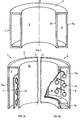
- the vacuum recipient 1 shows the vacuum recipient 1 according to the invention schematically.
- the treatment room 3 is spanned by an outer wall ring surface 5a and an inner 5i.
- the vacuum recipient 1 is constructed with walls 5a, 5i coaxial to an axis A, which is preferably and, as shown, vertical.
- volume V spanned by the inner wall ring surface 5i can be used for units of a vacuum treatment system with the vacuum recipient according to the invention.
- One preferred carrier arrangement comprises a cylinder 7, which is arranged, at a predetermined distance, in the treatment room 3 between the inner and outer wall ring surfaces 5i and 5a.
- the workpiece carrier cylinder 7 is preferably driven in the treatment room 3 in a manner still to be explained, about the axis A.
- the second preferred carrier arrangement comprises a carrier ring 7a, on which carrier arms 8 are mounted, which likewise together span a cylindrical surface.
- Workpieces 13, as shown schematically, are held on the support arms 8.
- the support ring 7a and thus the support arms 8 and the workpieces 13 are rotated in the annular space 3 around the axis A of the annular chamber.
- the workpieces 13 are held both on or in the carrier cylinder 7 and on the arms 8 by means of workpiece holders 13a, for example by means of resilient clips.
- FIG. 3 the three recipient parts, inner wall ring surface 5i, outer wall ring surface 5a and projecting workpiece carrier arrangement 7 or 7a, 8, are shown purely schematically, wherein, as is illustrated with the insulation 9, these three parts are electrically insulated from one another.
- Each of the three "ring surfaces", the outer wall ring surface 5a, the inner wall ring surface 5i and the workpiece carrier can, in principle as a three-electrode arrangement, be optionally electrically connected.
- “option selectors” 11 which are to be understood less as switchover units than as a graphic representation of the various options for electrically operating the parts mentioned relative to one another.
- the inner wall ring surface 5i can be supplied with DC or AC energy, right down to the RF range or even, in the case of a corresponding design known to the person skilled in the art, into the microwave range.
- the carrier arrangement 7 or 7a, 8 can be connected in a floating manner and the outer wall ring surface 5a can be set to reference potential or the carrier arrangement 7 or 7a, 8 together with outer wall ring surface 5a can be set to reference potential.
- the carrier arrangement 7 or 7a, 8 can also be set to the reference potential and at the same time the outer wall ring surface 5a can be set to DC or AC potential, again, if appropriate, up to the microwave range.
- 4a and 4b show, schematically, different configurations of the workpiece carrier cylinder 7 according to FIG. 2a, as one of the preferred variants of the carrier arrangement 7, 7a, 8.
- FIG. 4a it essentially consists of insulating material for the operation of the treatment room 3 according to FIG. 3 as a discharge zone space.
- workpieces 13 for example optical lenses made of a plastic
- retaining clips 13a in the plastic carrier cylinder 7
- significant parts 15 of the cylinder 7 being excluded, as can be seen from Fig. 4a, in order to enable the discharge built up between the wall rings 5i and 5a to penetrate, which is already the case when the arrangement 7a, 8 according to FIG. 2b is built up.
- at least essential parts of the carrier cylinder 7 consist of electrically conductive material.
- the carrier arrangement can be operated with other treatment sources as a bias arrangement for the workpieces.
- the carrier arrangement 7 or 7a, 8 is rotated between the wall ring surfaces in order to achieve maximum treatment homogeneity, as shown by the arrow F in FIG. 5. 6, this also gives the possibility of mounting discrete treatment stations 17 on the inner or outer wall ring surface, here shown schematically on the outer wall ring surface 5 a, such as sputter sources, heating sources, Etching sources, arc evaporation sources, electrode beam evaporation sources etc.
- discrete treatment stations 17 on the inner or outer wall ring surface, here shown schematically on the outer wall ring surface 5 a, such as sputter sources, heating sources, Etching sources, arc evaporation sources, electrode beam evaporation sources etc.
- the workpiece holder arrangement is in principle driven continuously in accordance with FIG. 5 when the recipient according to the invention is formed in order to achieve the highest possible treatment uniformity, it is preferably operated intermittently, that is to say in steps, in the formation according to FIG. 6, so that the workpieces held on or on the workpiece carrier arrangement 7 or
- the outer wall ring surface 5a comprises at least one door shell 19 which is pivotally mounted on pivot bearings 21 parallel to the ring axis A, as shown preferably two such door shells 19. This makes it possible for the treatment room 3 to be accessed in an optimal manner, be it to load or unload the intended workpiece carrier or to clean the treatment room.
- the preferably two provided door shells 19, as shown at 19a can be designed exclusively as shells of the outer ring surface 5a or, as indicated at 19 on the right, at least partially tub-like to include a bottom part 19c of the recipient. Between the two, however formed door shells 19 and 19a, a relatively narrow central web of the outer ring surface 5a remains stationary, which, as can be seen in FIG. 8, aggregates of the system, such as a pump connection 22 for the interior or gas connections 24 for work - or reactive gas are mounted.
- the carrier arrangement comprises a carrier plate 25, on which the cylinder described above, be it clamped by a carrier cylinder 7 itself according to FIG. 2a or discrete carrier arms 8 according to FIG. 2b, is peripherally, if necessary, interchangeably mounted.
- the support plate 25 is supported radially in its central region around the interior axis A and is axially supported or supported in its peripheral region, the peripheral axial bearing preferably being formed at least in part by a drive engagement on the plate 25, for which purpose the axial support 27 includes a drive wheel (not shown).
- FIG. 9b the functions of central and peripheral storage with respect to FIG. 9a are interchanged in that here the carrier plate 25 is axially supported in its central area and is mounted radially peripherally.
- the preferred separation of radial bearing and axial bearing shown in FIG. 9 ensures that the large diameter in many cases Carrier disc 25, determined statically, is moved with great precision without, for example in the case of plate diameters ⁇ 1 m, temperature-induced plate distortions having an effect on the exact movement of the carrier arrangement parts in accordance with 7, 7a or 8. In this way, complex constructive precautions on the carrier plate 25 itself are avoided, in order to ensure the above-mentioned precision even under operating conditions.
- the aforementioned carrier plate 25 is shown schematically in supervision.
- the plate 25 is preferably further designed so that it is elastically deformable in the axial direction A. It is thus achieved in its peripheral area, for example in connection with FIG. 9a, that its own weight and that of the projecting workpiece carrier arrangement parts 7 etc. permanently press it flush onto the axial bearing 27 or the organs forming this bearing.
- the carrier plate 25 preferably comprises a spoke-like structure with spokes 25a, which, paired with an appropriate choice of an elastic material, at least for parts of the plate and / or their corresponding thickness dimensioning, ensures the abovementioned support, while at the same time also small dark space distances of, for example, 3 mm between the plate surface and neighboring, stationary recipient parts by avoiding mechanical wobbling of the plate.
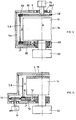
- FIG. 1 A preferred embodiment variant of the recipient according to the invention is shown schematically in FIG. The same item numbers are assigned to the parts that have been explained in principle up to now.
- the annular treatment space 3, divided into the treatment spaces 3i and 3a, is radially delimited by the inner wall ring surface 5i and the outer wall ring surface 5a.
- the annular surfaces 5i and 5a are each formed by a coaxial chamber 27i and 27a, the inner chamber 27i being separated from the outer 27a by electrical insulation 29. While the upper end plates 28i and 28a of the two chambers are kept at a distance from the dark room, the support plate 25 lies between the lower end plates 29i and 29a of the chamber mentioned.
- the preferred recipient not shown here, comprises two door shells on the outer wall ring surface 5a. If the central volume V is to be used for plant units, the upper end plates 28a and 28i are omitted, and instead the upper endings of the wall ring surfaces 5i and 5a are insulated and connected in a vacuum-tight manner.
- helmwood coils 44 are preferably provided in order to generate a magnetic field B essentially parallel to the axis A in the treatment room 3 if such a magnetic field is required in the treatment process carried out with the recipient.
- the resulting magnetic field B is also shown in FIGS. 7 and 8 in one of the possible polarities.
- the workpiece carrier cylinder 7 or workpiece carrier arm structures do not necessarily have to be arranged symmetrically between the inner and outer wall ring surfaces, as shown, but, depending on the intended treatment, can also be closer to one of the two wall ring surfaces. Due to the high precision of movement, in particular the periphery of the support plate 25, under Compliance with the dark space distances to the lower end plates 29a and 29i results in the workpieces being moved with a correspondingly high precision at a given distance from the ring surfaces, which are operated electrically as electrode surfaces, depending on the intended treatment method, according to FIG. 3.
- the electrical circuits, in particular the ring surfaces 5i and 5a and the workpiece carrier 7 and 7a, 8 are not entered in FIG. 11, but all three are insulated from one another, so that one of the previously explained types of wiring can be carried out.
- FIG. 12 to 15 schematically show further design variants of the treatment plant according to the invention, with FIG. 15, as mentioned, schematically representing one of the configurations preferred today.
- the inner wall ring surface 5i forms the RF electrode connected to a high-frequency generator, shown in the unit 50, via a matching network.
- the outer wall ring surface 5a forms the counter electrode here, for example, at ground potential.
- the wall ring surface 5i forming the high-frequency electrode is electrically insulated from the bottom surface 54 of the recipient, which is operated at the same potential with the outer wall ring surface 5a.
- the carrier plate 58 is preferably continuously driven in rotation.
- the carrier plate 58 is preferably made of dielectric material.
- An outer ring 60 is removably inserted on the carrier plate 58, from which the above-described carriers 7 and 8 hang.
- lids 59 are lifted, as shown schematically by the arrows, which are sealed with seals 62 in the closed state with respect to the mounting flange 56, and the outer ring 60 with the batch is placed on the plate 58.
- this configuration also allows a treatment room 3 to be created with optimally few dead spaces, which is essential in terms of keeping the treatment room clean.
- the treatment room 3 is also easily accessible and only a shaft seal for the motor shaft on the mounting flange 56 is necessary.
- the workpieces are held at floating potential in the treatment room 3 as shown in FIG. 12, it is entirely possible to apply a bias potential to the workpieces in a targeted manner.
- the inner wall ring 5i of the treatment room 3 in turn forms the HF electrode.
- the outer wall ring 5a is in turn closed off at the top by removable covers 58.
- the motor 54 held in the mounting flange 56 acts on the carrier plate 58, which is preferably made of dielectric material, at which, peripherally, the ring 60 is in azimuthal engagement.
- the supports 7, 8 are supported here on a lower support plate 66 which, axially fixed, on bearings, for example ball bearings 68 with respect to the HF feedthrough to the HF electrode, corresponding to the inner wall ring 5i , is rotatably mounted.
- the surfaces of the rotationally driven carrier arrangement that are curved in the immediate vicinity of the HF-exposed surfaces of the core 64 of the recipient formed by the inner wall surface 5i are preferably made of dielectric material.
- the drive via motor 54 takes place azimuthally on the ring 60 via the plate 58, is transmitted via the carriers 7, 8 to the lower plate 66, on which the carriers are supported axially.
- the substrate carrier arrangement can already be charged in order to charge the system after removing the covers 59, introduced as a whole into the treatment room 3 or removed therefrom.
- the inner wall surface 5i in turn forms an HF electrode and is connected to the adaptation network and the HF generator in the unit 50 for this purpose.
- a lower support plate 70 rotatably mounted on bearings 72 and axially fixed, the support arrangements or the support arrangement 7, 8, as shown schematically, are on a base ring 74.
- the plate 70 is driven by the drive motor 74 and friction wheel 76.
- the treatment room 3 is closed by a removable cover 78, as indicated by the arrow, after its opening, the carrier arrangement 7, 8 with the ring 74, preferably as a whole, can be removed from the treatment room 3.
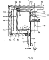
- the drive motor 80 Centrally to the axis A of the treatment chamber 3, which is also ring-shaped here, the drive motor 80 is provided for the carrier arrangement, which acts on the carrier plate 90 via a coupling 82, a shaft 88 mounted in bearings 84 and seals 86. Motor and plate drive are mounted within the inner wall ring 5i of the treatment room 3.
- the wall ring 5i as an HF electrode, is connected via a feedthrough 92 to an adaptation network and the high-frequency generator (not shown).
- the central space 94 of the arrangement, with the motor 80, the supply lines for this, etc., is shielded by means of a shield cylinder 96, which is at the same potential as the outer wall surface 5a acting as an electrode.
- the central, upper part of the core 64 of the recipient, which carries the inner wall ring 5i, is, as shown at 98, electrically connected to the reference potential by the outer part exposed to high frequency with the wall surface 5i and as a whole via the shield cylinder 96.
- a carrier ring 102 is supported on the periphery of the carrier plate 90, from the central part of which, as shown at 100, in an electrically insulated manner the carrier arrangement 7, 8 hangs or the carrier arrangement hangs.
- the outer wall with the outer wall ring 5a of the treatment room 3 carries lines of a gas distribution system 104 with, as shown, for example, upstanding gas ejection rods 106 for the admission of a reactive gas into the treatment room 3.
- reactive gas preferably on both sides of the carrier arrangement 7, 8, is admitted into the treatment annulus 3.
- Pump connections for pumping out the treatment room 3 are also preferably central, i.e. provided coaxially to the axis A, and the pumping out of the treatment room 3 is carried out through appropriately sized openings 104.
- the treatment room 3 is charged via a removable cover 110, as already described, or via one or two pivoting doors, as was explained with reference to FIGS. 7, 8.
- the most important thing about the last system configuration shown is the utilization of the central part surrounded by the inner wall ring 5i for pump connections and rotary drive of the carrier arrangement.
- a magnetic field is optionally generated axially in the treatment room 3, as is additionally the case with the coils 44 using FIG.
- the treatment room 3 or the inner and outer ring surfaces 5i, 5a are lined with removable sheets 108 which can be easily removed from the room 3 for cleaning.
- the diameter of the treatment room is more than 1 m
- the radial width of the treatment room is in the range of a few cm, for example of approximately 7 cm .
Landscapes
- Chemical & Material Sciences (AREA)
- Chemical Kinetics & Catalysis (AREA)
- Engineering & Computer Science (AREA)
- Materials Engineering (AREA)
- Mechanical Engineering (AREA)
- Metallurgy (AREA)
- Organic Chemistry (AREA)
- Physical Vapour Deposition (AREA)
- Plasma Technology (AREA)
Claims (21)
- Installation de traitement sous vide pour des pièces à traiter, comprenant un espace de traitement cylindrique extérieur (3) et un dispositif de support rotatif (7, 7a, 8) pour plusieurs pièces (13) dans l'espace de traitement (3), lequel dispositif de support est relié à un entraînement en rotation, étant précisé que la paroi de l'espace de traitement est apte à être ouverte sur une grande surface pour permettre de charger et de décharger les pièces (13) dans l'espace de traitement (3), caractérisée en ce que l'espace de traitement (3) est défini par deux surfaces de paroi (5a, 5i) sensiblement cylindriques et coaxiales, et le dispositif de support (7, 7a, 8) dépasse entre les surfaces de paroi.
- Installation selon la revendication 1, caractérisée en ce que l'espace de traitement (3) est conçu, sur sa surface intérieure et/ou extérieure radiale, comme une électrode circulaire annulaire destinée à produire une décharge de plasma dans l'espace de traitement (3).
- Installation selon l'une des revendications 1 ou 2, caractérisée en ce que la paroi intérieure coaxiale (5i) de l'espace de traitement (3) est accouplée à un générateur haute fréquence (50) pour produire une décharge de plasma haute fréquence.
- Installation selon l'une des revendications 1 à 3, caractérisée en ce que des éléments d'installation supplémentaires, notamment un entraînement en rotation (80) pour le dispositif de support et/ou un raccordement de pompe, sont prévus radialement à l'intérieur de la surface de paroi intérieure (5i).
- Installation selon l'une des revendications 1 à 4, caractérisée en ce que le dispositif de support est relié à un entraînement en rotation continu.
- Installation selon l'une des revendications 1 à 5, caractérisée en ce que le dispositif de support (7, 7a, 8) couvre une surface cylindrique sur laquelle sont répartis des porte-pièces (13a).
- Installation selon l'une des revendications 1 à 6, caractérisée en ce que la surface de paroi radialement extérieure (5a) est apte à être ouverte sur une grande surface (2) pour le chargement et le déchargement de l'espace de traitement (3).
- Installation selon l'une des revendications 1 à 7, caractérisée en ce qu'au moins une partie terminale frontale (4) de l'espace de traitement (3) est apte à être ouverte pour le chargement et le déchargement de l'espace de traitement (3).
- Installation selon l'une des revendications 1 à 8, caractérisée en ce que le dispositif de support couvre une surface cylindrique à l'aide de supports discrets (8) qui sont sensiblement parallèles à l'axe (A) des surfaces de paroi coaxiales et qui sont prévus pour une ou plusieurs pièces (13), ou à l'aide d'un cylindre de support (7).
- Installation selon l'une des revendications 1 à 9, caractérisée en ce que l'espace de traitement (3) est disposé sensiblement suivant un axe vertical (A), et il est prévu pour le dispositif de support (7, 7a, 8) des coussinets de pivotement disposés en bas par rapport à l'espace de traitement (3), et de préférence un contact entre l'entraînement et le dispositif de support.
- Installation selon l'une des revendications 1 à 10, caractérisée en ce que le dispositif de support (7, 7a, 8) est monté mobile en rotation au centre et est entraîné de préférence dans la zone périphérique.
- Installation selon l'une des revendications 1 à 11, caractérisée en ce que le dispositif de support est monté radialement au centre et axialement à la périphérie ou inversement, et en ce qu'un contact d'entraînement au centre ou à la périphérie est de préférence prévu avec le dispositif de support et constitue de préférence au moins un élément de l'un des montages mentionnés.
- Installation selon l'une des revendications 1 à 12, caractérisée en ce que le dispositif de support comprend une plaque de support montée mobile en rotation (25) qui est apte à être déformée élastiquement grâce au choix du matériau et/ou à des déformations, qui présente de préférence une structure à rayons et qui est en appui de préférence à la périphérie dans le sens de l'axe (A) de l'espace de traitement.
- Installation selon l'une des revendications 1 à 13, caractérisée en ce qu'un moteur d'entraînement prévu pour le dispositif de support agit sur celui-ci par l'intermédiaire d'une roue d'entraînement (37).
- Installation selon l'une des revendications 1 à 14, caractérisée en ce que les porte-pièces sont montés sur le dispositif de support en étant isolés électriquement des autres éléments de l'installation et sont éventuellement mis de façon appropriée à un potentiel électrique.
- Installation selon l'une des revendications 1 à 15, caractérisée en ce que les porte-pièces (13a) prévus sur le dispositif de support sont déplacés, sensiblement équidistants, entre les surfaces de paroi (3).
- Installation selon l'une des revendications 1 à 16, caractérisée en ce que les porte-pièces (13a) prévus sur le dispositif de support fonctionnent à un potentiel flottant.
- Installation selon l'une des revendications 1 à 17, caractérisée en ce que des parties au moins de la paroi extérieure et/ou intérieure (5a, 5i) de l'espace de traitement annulaire (3) et des parties au moins des porte-pièces (13a) sont aptes à fonctionner électriquement indépendamment les unes des autres comme dispositif à trois électrodes.
- Utilisation de l'installation selon l'une des revendications 1 à 18 pour le traitement simultané de composants optiques sur deux côtés, en particulier pour le revêtement de ces composants.
- Utilisation selon la revendication 19 pour le revêtement simultané et sensiblement identique de composants optiques sur deux côtés.
- Utilisation selon l'une des revendications 19 ou 20 pour le revêtement de composants optiques grâce à la polymérisation par plasma.
Applications Claiming Priority (2)
| Application Number | Priority Date | Filing Date | Title |
|---|---|---|---|
| CH3851/91 | 1991-12-27 | ||
| CH385191 | 1991-12-27 |
Publications (2)
| Publication Number | Publication Date |
|---|---|
| EP0550003A1 EP0550003A1 (fr) | 1993-07-07 |
| EP0550003B1 true EP0550003B1 (fr) | 1996-01-17 |
Family
ID=4264843
Family Applications (1)
| Application Number | Title | Priority Date | Filing Date |
|---|---|---|---|
| EP92121849A Expired - Lifetime EP0550003B1 (fr) | 1991-12-27 | 1992-12-23 | Appareillage de traitement sous vide et ses utilisations |
Country Status (4)
| Country | Link |
|---|---|
| US (1) | US5370737A (fr) |
| EP (1) | EP0550003B1 (fr) |
| JP (1) | JPH05247632A (fr) |
| DE (1) | DE59205106D1 (fr) |
Cited By (1)
| Publication number | Priority date | Publication date | Assignee | Title |
|---|---|---|---|---|
| DE102006032959B3 (de) * | 2006-07-17 | 2007-12-27 | JOH. WINKLHOFER & SÖHNE GMBH & Co. KG | Werkstückträger für Vakuumbeschichtungsanlagen mit magnetischen Aufnahmekörpern |
Families Citing this family (22)
| Publication number | Priority date | Publication date | Assignee | Title |
|---|---|---|---|---|
| US5580384A (en) * | 1989-09-22 | 1996-12-03 | Balzers Aktiengesellschaft | Method and apparatus for chemical coating on opposite surfaces of workpieces |
| WO1994014530A1 (fr) * | 1992-12-28 | 1994-07-07 | Kao Corporation | Procede et appareil permettant de produire de fines particules de ceramique |
| GB9317170D0 (en) * | 1993-08-18 | 1993-10-06 | Applied Vision Ltd | Improvements in physical vapour deposition apparatus |
| JP3513206B2 (ja) * | 1994-03-22 | 2004-03-31 | キヤノン株式会社 | 堆積膜形成方法及び堆積膜形成装置 |
| US5523261A (en) * | 1995-02-28 | 1996-06-04 | Micron Technology, Inc. | Method of cleaning high density inductively coupled plasma chamber using capacitive coupling |
| US6010600A (en) * | 1996-02-22 | 2000-01-04 | The Regents Of The University Of California | Maskless deposition technique for the physical vapor deposition of thin film and multilayer coatings with subnanometer precision and accuracy |
| DE19737548A1 (de) * | 1997-08-28 | 1999-03-04 | Inst Oberflaechenmodifizierung | Kipp-, rotier- und thermostatierbare Substratstation zum Ionenstrahlätzen |
| JP4446597B2 (ja) * | 1997-10-20 | 2010-04-07 | ザ リージェンツ オブ ザ ユニバーシティ オブ カリフォルニア | 常圧プラズマジェットを使用したコーティングのデポジット |
| US20020110700A1 (en) * | 2001-02-12 | 2002-08-15 | Hein Gerald F. | Process for forming decorative films and resulting products |
| US6869645B2 (en) * | 2001-10-23 | 2005-03-22 | Acushnet Company | Method for plasma treatment of golf balls |
| DE10202311B4 (de) * | 2002-01-23 | 2007-01-04 | Schott Ag | Vorrichtung und Verfahren zur Plasmabehandlung von dielektrischen Körpern |
| US20050082089A1 (en) * | 2003-10-18 | 2005-04-21 | Stephan Grunow | Stacked interconnect structure between copper lines of a semiconductor circuit |
| DE202006007937U1 (de) * | 2006-05-18 | 2007-09-20 | Strämke, Siegfried, Dr.-Ing. | Plasmabehandlungsanlage |
| CN101994090B (zh) * | 2009-08-14 | 2013-06-05 | 鸿富锦精密工业(深圳)有限公司 | 溅镀载具及包括该溅镀载具的溅镀装置 |
| CN102021522B (zh) * | 2009-09-11 | 2013-06-05 | 鸿富锦精密工业(深圳)有限公司 | 溅镀式镀膜装置 |
| CN102061449B (zh) * | 2009-11-16 | 2013-06-05 | 鸿富锦精密工业(深圳)有限公司 | 真空镀膜装置 |
| US10808319B1 (en) | 2010-02-26 | 2020-10-20 | Quantum Innovations, Inc. | System and method for vapor deposition of substrates with circular substrate frame that rotates in a planetary motion and curved lens support arms |
| US10550474B1 (en) | 2010-02-26 | 2020-02-04 | Quantum Innovations, Inc. | Vapor deposition system |
| US20130092528A1 (en) * | 2010-06-30 | 2013-04-18 | Ulvac, Inc. | Film-forming device and film-forming method |
| JP2013040357A (ja) * | 2011-08-11 | 2013-02-28 | Optorun Co Ltd | 成膜装置 |
| DE102012104475A1 (de) * | 2012-05-24 | 2013-11-28 | Aixtron Se | Carousel-Reactor |
| US11646182B2 (en) * | 2019-12-18 | 2023-05-09 | Jiangsu Favored Nanotechnology Co., Ltd. | Coating apparatus and coating method |
Family Cites Families (6)
| Publication number | Priority date | Publication date | Assignee | Title |
|---|---|---|---|---|
| US3856654A (en) * | 1971-08-26 | 1974-12-24 | Western Electric Co | Apparatus for feeding and coating masses of workpieces in a controlled atmosphere |
| US3892198A (en) * | 1974-06-27 | 1975-07-01 | Christopher David Dobson | Enclosures for vacuum coating |
| DE3624467A1 (de) * | 1986-07-19 | 1988-01-28 | Leybold Heraeus Gmbh & Co Kg | Verfahren zum herstellen transparenter schutzschichten aus siliziumverbindungen |
| US4849250A (en) * | 1988-01-27 | 1989-07-18 | Storage Technology Corporation | Method and apparatus for producing magnetically oriented films on substrates |
| DE3912297C2 (de) * | 1989-04-14 | 1996-07-18 | Leybold Ag | Katodenzerstäubungsanlage |
| DE3921672C2 (de) * | 1989-07-01 | 1996-12-05 | Leybold Ag | Vorrichtung zum Halten und Wenden von Linsen, insbesondere für in einer Hochvakuum-Aufdampfanlage oder -Sputteranlage zu beschichtende Brillenglaslinsen |
-
1992
- 1992-12-23 EP EP92121849A patent/EP0550003B1/fr not_active Expired - Lifetime
- 1992-12-23 DE DE59205106T patent/DE59205106D1/de not_active Expired - Fee Related
- 1992-12-28 US US07/997,362 patent/US5370737A/en not_active Expired - Fee Related
- 1992-12-28 JP JP4349526A patent/JPH05247632A/ja active Pending
Cited By (1)
| Publication number | Priority date | Publication date | Assignee | Title |
|---|---|---|---|---|
| DE102006032959B3 (de) * | 2006-07-17 | 2007-12-27 | JOH. WINKLHOFER & SÖHNE GMBH & Co. KG | Werkstückträger für Vakuumbeschichtungsanlagen mit magnetischen Aufnahmekörpern |
Also Published As
| Publication number | Publication date |
|---|---|
| US5370737A (en) | 1994-12-06 |
| EP0550003A1 (fr) | 1993-07-07 |
| JPH05247632A (ja) | 1993-09-24 |
| DE59205106D1 (de) | 1996-02-29 |
Similar Documents
| Publication | Publication Date | Title |
|---|---|---|
| EP0550003B1 (fr) | Appareillage de traitement sous vide et ses utilisations | |
| EP0632846B1 (fr) | Dispositif a enduire sous vide des produits en vrac | |
| DE60036631T2 (de) | Plasmabehandlungsapparatur und plasmabehandlungsverfahren | |
| DE69204670T2 (de) | Sanftaetz-einheit fuer modulare bearbeitungsanlagen und ecr-plasmaerzeuger fuer eine solche einheit. | |
| DE69023633T2 (de) | Kathodenzerstäubungsgerät und kathodenzerstäubungsanlage. | |
| EP2373828B1 (fr) | Dispositif de traitement et/ou de revêtement de surface de composants de substrat | |
| DE69835324T2 (de) | Dampfphasenabscheidungsgerät mit kathodischem Lichtbogen (Ringförmige Kathode) | |
| EP1186681B1 (fr) | Dispositif de traitement sous vide avec support de substrats couplable | |
| DE2400510A1 (de) | Verfahren und einrichtung zur herstellung eines duennfilmbelages auf einem traeger | |
| EP0518109B1 (fr) | Système de traitement sous vide | |
| EP0444618A2 (fr) | Dispositif de traitement par plasma | |
| DE3507337A1 (de) | Vorrichtung zur durchfuehrung von prozessen im vakuum | |
| EP0888463A1 (fr) | Dispositif de depot sous vide sur des matieres en vrac | |
| DE1615287A1 (de) | Vorrichtung zur Aufbringung duenner Schichten auf Glas oder andere Materialien unter Vakuum | |
| DE69524009T2 (de) | Verfahren zum beschichten von substraten | |
| EP0490028B1 (fr) | Système de couches sur la surface d'un matériau et procédé pour sa fabrication | |
| EP0837154A1 (fr) | Appareillage de revêtement sous vide | |
| EP3061127A1 (fr) | Agencement de plusieurs magnétrons | |
| DE69715180T2 (de) | Magnetanordnung für magnetrone | |
| DE69128544T2 (de) | Verfahren und vorrichtung zur sputtenbeschichtung mit rotierender magnetischer kathode | |
| DE69305725T2 (de) | Magnetron-Zerstäubungsvorrichtung und Dünnfilm-Beschichtungsverfahren | |
| EP0492114A1 (fr) | Appareillage de pulvérisation | |
| DE19617155B4 (de) | Sputterbeschichtungsstation, Verfahren zur Herstellung sputterbeschichteter Werkstücke und Verwendung der Station oder des Verfahrens zur Beschichtung scheibenförmiger Substrate | |
| DE102013107659A1 (de) | Plasmachemische Beschichtungsvorrichtung | |
| DE19624609B4 (de) | Vakuumbehandlungsanlage zum Aufbringen dünner Schichten auf Substrate, beispielsweise auf Scheinwerferreflektoren |
Legal Events
| Date | Code | Title | Description |
|---|---|---|---|
| PUAI | Public reference made under article 153(3) epc to a published international application that has entered the european phase |
Free format text: ORIGINAL CODE: 0009012 |
|
| AK | Designated contracting states |
Kind code of ref document: A1 Designated state(s): CH DE FR IT LI NL |
|
| 17P | Request for examination filed |
Effective date: 19930729 |
|
| 17Q | First examination report despatched |
Effective date: 19940809 |
|
| GRAA | (expected) grant |
Free format text: ORIGINAL CODE: 0009210 |
|
| AK | Designated contracting states |
Kind code of ref document: B1 Designated state(s): CH DE FR IT LI NL |
|
| PG25 | Lapsed in a contracting state [announced via postgrant information from national office to epo] |
Ref country code: IT Free format text: LAPSE BECAUSE OF FAILURE TO SUBMIT A TRANSLATION OF THE DESCRIPTION OR TO PAY THE FEE WITHIN THE PRE;WARNING: LAPSES OF ITALIAN PATENTS WITH EFFECTIVE DATE BEFORE 2007 MAY HAVE OCCURRED AT ANY TIME BEFORE 2007. THE CORRECT EFFECTIVE DATE MAY BE DIFFERENT FROM THE ONE RECORDED.SCRIBED TIME-LIMIT Effective date: 19960117 Ref country code: FR Effective date: 19960117 Ref country code: NL Free format text: LAPSE BECAUSE OF FAILURE TO SUBMIT A TRANSLATION OF THE DESCRIPTION OR TO PAY THE FEE WITHIN THE PRESCRIBED TIME-LIMIT Effective date: 19960117 |
|
| REF | Corresponds to: |
Ref document number: 59205106 Country of ref document: DE Date of ref document: 19960229 |
|
| EN | Fr: translation not filed | ||
| NLV1 | Nl: lapsed or annulled due to failure to fulfill the requirements of art. 29p and 29m of the patents act | ||
| PLBE | No opposition filed within time limit |
Free format text: ORIGINAL CODE: 0009261 |
|
| STAA | Information on the status of an ep patent application or granted ep patent |
Free format text: STATUS: NO OPPOSITION FILED WITHIN TIME LIMIT |
|
| 26N | No opposition filed | ||
| PGFP | Annual fee paid to national office [announced via postgrant information from national office to epo] |
Ref country code: CH Payment date: 20030526 Year of fee payment: 11 |
|
| PG25 | Lapsed in a contracting state [announced via postgrant information from national office to epo] |
Ref country code: LI Free format text: LAPSE BECAUSE OF NON-PAYMENT OF DUE FEES Effective date: 20031231 Ref country code: CH Free format text: LAPSE BECAUSE OF NON-PAYMENT OF DUE FEES Effective date: 20031231 |
|
| PGFP | Annual fee paid to national office [announced via postgrant information from national office to epo] |
Ref country code: DE Payment date: 20040102 Year of fee payment: 12 |
|
| REG | Reference to a national code |
Ref country code: CH Ref legal event code: PL |
|
| PG25 | Lapsed in a contracting state [announced via postgrant information from national office to epo] |
Ref country code: DE Free format text: LAPSE BECAUSE OF NON-PAYMENT OF DUE FEES Effective date: 20050701 |