EP0550192A2 - Imprimante acoustique à encre - Google Patents
Imprimante acoustique à encre Download PDFInfo
- Publication number
- EP0550192A2 EP0550192A2 EP92311381A EP92311381A EP0550192A2 EP 0550192 A2 EP0550192 A2 EP 0550192A2 EP 92311381 A EP92311381 A EP 92311381A EP 92311381 A EP92311381 A EP 92311381A EP 0550192 A2 EP0550192 A2 EP 0550192A2
- Authority
- EP
- European Patent Office
- Prior art keywords
- substrate
- transducer
- layer
- printhead
- electrode
- Prior art date
- Legal status (The legal status is an assumption and is not a legal conclusion. Google has not performed a legal analysis and makes no representation as to the accuracy of the status listed.)
- Granted
Links
Images


Classifications
-
- B—PERFORMING OPERATIONS; TRANSPORTING
- B41—PRINTING; LINING MACHINES; TYPEWRITERS; STAMPS
- B41J—TYPEWRITERS; SELECTIVE PRINTING MECHANISMS, i.e. MECHANISMS PRINTING OTHERWISE THAN FROM A FORME; CORRECTION OF TYPOGRAPHICAL ERRORS
- B41J2/00—Typewriters or selective printing mechanisms characterised by the printing or marking process for which they are designed
- B41J2/005—Typewriters or selective printing mechanisms characterised by the printing or marking process for which they are designed characterised by bringing liquid or particles selectively into contact with a printing material
- B41J2/01—Ink jet
- B41J2/135—Nozzles
- B41J2/14—Structure thereof only for on-demand ink jet heads
- B41J2/14008—Structure of acoustic ink jet print heads
-
- B—PERFORMING OPERATIONS; TRANSPORTING
- B41—PRINTING; LINING MACHINES; TYPEWRITERS; STAMPS
- B41J—TYPEWRITERS; SELECTIVE PRINTING MECHANISMS, i.e. MECHANISMS PRINTING OTHERWISE THAN FROM A FORME; CORRECTION OF TYPOGRAPHICAL ERRORS
- B41J2/00—Typewriters or selective printing mechanisms characterised by the printing or marking process for which they are designed
- B41J2/005—Typewriters or selective printing mechanisms characterised by the printing or marking process for which they are designed characterised by bringing liquid or particles selectively into contact with a printing material
- B41J2/01—Ink jet
- B41J2/135—Nozzles
- B41J2/14—Structure thereof only for on-demand ink jet heads
- B41J2002/14322—Print head without nozzle
Definitions
- This invention relates to acoustic ink printers, and in particular to a printhead for an acoustic ink printer.
- U.S. Patents Nos. 4,751,530, Elrod et al, 4,751,534, Elrod et al, and 4,751,529, Elrod et a disclose printheads for acoustic ink printers, wherein an acoustic transducer is deposited or otherwise coupled to the lower surface of a substrate, and a concave lens is formed in the opposite surface of the substrate.
- the lens which may have a quarter wave impedance matching layer to avoid the reflection of waves back to the transducer, focuses the acoustic beam at a point near the surface of an ink pool adjacent the upper surface of the substrate.
- the transducer in these arrangements may comprise a piezoelectric element sandwiched between a pair of electrodes, to excite the piezoelectric element into a thickness mode oscillation. Modulation of RF excitation applied to the piezoelectric element causes the radiation pressure, which the focused acoustic beam exerts against the upper surface of the pool of ink, to swing above and below a predetermined droplet ejection threshold level as a function of demand.
- crosstalk due to near field diffraction of nominally planar sound waves, in a typical substrate can adversely affect eject on stability and precision.
- intensity crosstalk due to near field diffraction is computed to be 3.7%. This is a substantial fraction of the acoustic ink printer 10% power regulation, within which it is desired to maintain the power, and can noticeably contribute to crosstalk.
- Acoustic ink printheads are also disclosed, for example, in U.S. Patent No. 4,719,476, Elrod et al, U.S. Patent No. 4,719,480, Elrod et al, U.S. Patent No. 4,748,461, Elrod, U.S. Patent No. 4,782,350, Smith et al, U.S. Patent No. 4,797,693, Quate, and U.S. Patent No. 4,801,953, Quate.
- the present invention provides a printhead for an acoustic printer, comprising a substrate, an acoustic transducer on a first surface of said substrate, a dielectric layer on said transducer, and a lens formed in said dielectric layer.
- Said acoustic transducer may comprise a body of piezoelectric material, and may further comprise first and second electrodes on opposite sides of said body of piezoelectric material, whereby said layer of dielectric material is in contact with said second electrode.
- Said first electrode may be comprised of a thin layer, for example of aluminum.
- the first electrode may have a thickness of quarter of a wavelength at the frequency of the output of an excitation source that is connected between the first and second electrodes.
- the first electrode may be gold.
- the lens may comprise a Fresnel lens formed in said dielectric layer.
- the present invention further provides, in a printhead arranged for an acoustic ink printer, wherein a transducer is provided for generating an acoustic wave, and a lens is mounted to focus said wave near a surface of a body of ink, the improvement comprising a substrate having first and second surfaces, said transducer having a first surface supported on said first surface of said substrate and a second surface opposite said first surface of said transducer, and a layer of a dielectric material on said second surface of said transducer, said lens comprising a lens formed in the surface of said dielectric layer opposite said second electrode of said transducer.
- the lens may comprise a Fresnel lens.
- said transducer comprises a layer of a piezoelectric material sandwiched between first and second electrodes, with said first and second electrodes defining said first and second surfaces, respectively, of said transducer, and further comprising an excitation source connected between said first and second electrodes, said second electrodes being connected to a reference potential.
- said substrate has a pit extending through between said first and surfaces thereof, said pit being aligned with said transducer.
- said transducer comprises a layer of a piezoelectric material sandwiched between first and second electrodes, with said first electrode defining said first surface of said transducer, and further comprising an excitation source connected between said first and second electrodes for exciting said transducer at a given frequency, said first electrode having a thickness of a quarter wave at said frequency.
- said transducer comprises a layer of a piezoelectric material sandwiched between first and second electrodes, with said first electrode defining said first surface of said transducer, and further comprising an excitation source connected between said first and second electrodes for exciting said transducer at a given frequency, and a layer of an anti-reflection material of a thickness of a quarter wave at said frequency on said second surface of said substrate, and further comprising a body of a sound absorptive material abutting said layer of anti-reflection material.
- said transducer comprises a layer of a piezoelectric material sandwiched between first and second electrodes, with said first electrode defining said first surface of said transducer, and further comprising an excitation source connected between said first and second electrodes for exciting said transducer at a given frequency, and a layer of sound absorbing material on said second surface of said substrate, said sound absorbing material having a Z which approximately matches that of said substrate.
- An acoustic ink printer printhead in accordance with the invention may have a substrate of, for example, silicon.
- a lower electrode layer for example of Ti-Au, is provided on the top of the substrate, for receiving an RF input.
- a piezoelectric layer that is either a half-wavelength or a quarter-wavelength thick, for example of ZnO, is deposited on the lower electrode.
- Either a thin Al electrode (in the case of a half-wavelength thick piezoelectric layer) or a quarter wavelength plated gold electrode (in the case of a quarter wavelength thick piezoelectric layer) is provided on the top of the piezoelectric layer, and is adapted to be grounded in use to avoid capacitive coupling to the conductive liquid ink.
- a Fresnel lens of polyimide or paralene is provided on top of the upper electrode.
- a liquid ink layer is maintained above the Fresnel lens.
- the piezoelectric element is very close to the Fresnel lens, to minimize crosstalk.
- an acoustic ink printer printhead comprising a substrate 10, for example a glass substrate.
- a substrate 10 for example a glass substrate.
- One or more thin Ti-Au layers 11 are provided on the top of the substrate 10, to serve as lower electrodes for the transducers.
- Separate layers 12 of piezoelectric material such as ZnO are grown on the layers 11, and separate upper electrodes 13, for example of a thin layer (e.g. 1IJm) of aluminum or a quarter wave thickness gold, are provided on the upper surfaces of the piezoelectric transducers.
- the upper electrodes have diameters, for example, of 340IJm.
- the upper and lower electrodes are connected to a source 25 of conventionally modulated RF power.
- a dielectric layer 14 is deposited on top of the above described structure, the dielectric layer being, for example, of polyimide or paralene. This dielectric layer is thin compared to the diameters of the upper gold electrodes, and may be, for example, 20 to 50IJm thick.
- Fresnel lenses 15 are etched in the top of the dielectric layer above each of the piezoelectric transducers. As a consequence, the lenses lie in a plane that is very close to the planes of the transducers.
- the above described structure may be fabricated in accordance with conventional techniques.
- the close proximity of the Fresnel lenses to the planes of the transducers essentially eliminates or substantially mitigates any crosstalk between the transducers that results from diffraction of the sound waves between the transducers and the lenses.
- the upper electrodes are connected to reference potentials, such as ground reference, and the driving signal voltages are applied to the lower electrodes 11.
- reference potentials such as ground reference
- the characteristic impedance Z of a material in an abbreviated form.
- the acoustic ink printhead of Fig. 1 When using the acoustic ink printhead of Fig. 1, once a significant acoustic power has been launched into the dielectric layer, a relatively high proportion of that power is coupled from the dielectric into the ink, which may be a liquid.
- This result constitutes a significant improvement when compared with conventional printheads. For example, in one conventional arrangement, wherein power was coupled from 7740 Pyrex (having a Z of 12.5) into water, the coupling loss was 2.1 dB.
- the substrate 10 may be a ⁇ 111 ⁇ oriented single crystal Si, the crystal being etched away under each of the transducers to form a cylindrical pit 19 extending to the respective lower electrode 11, as illustrated in Figs. 3 and 4.
- This results in the provision of an air interface 20 at the lower side of each of the transducers that has such a low impedance (Z 0.000043) that essentially no acoustic energy is transmitted in the downward direction, resulting in the radiation of substantially all of the power in the upward direction into the ink, as desired.
- Z 62.6
- the impedance of the quarter wave thickness electrodes substantially mismatches the impedance of the substrate, very little acoustic power is radiated downwardly into the substrate.
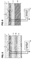
- a quarter wave anti-reflection coating 30 may be provided on the bottom surface of the substrate, as illustrated in Fig. 5, thereby coupling the sound efficiently into a material 31 below the substrate which is acoustically absorptive.
- a quarter wave coating of paralene under the substrate 10 forms an effective anti-reflection coating into the layer 31, which may be a viscous fluid, such as mineral oil, to effectively absorb the ultrasound.
- FIG. 6 A further modification is illustrated in Fig. 6, which differs from the embodiment of the invention illustrated in Fig. 5 in that the coating 30 and material 31 are replaced by a material 32 with a Z which approximately matches the substrate (for example, epoxy). This eliminates the need for the anti-reflection layer 30 and eliminates the complexity of using a liquid material 31, such as mineral oil, for the rear surface sound absorber.
- a liquid material 31 such as mineral oil
- lens and transducers are preferably round, they are not limited to this shape.
Landscapes
- Particle Formation And Scattering Control In Inkjet Printers (AREA)
- Recording Measured Values (AREA)
Applications Claiming Priority (2)
| Application Number | Priority Date | Filing Date | Title |
|---|---|---|---|
| US815730 | 1991-12-30 | ||
| US07/815,730 US5339101A (en) | 1991-12-30 | 1991-12-30 | Acoustic ink printhead |
Publications (3)
| Publication Number | Publication Date |
|---|---|
| EP0550192A2 true EP0550192A2 (fr) | 1993-07-07 |
| EP0550192A3 EP0550192A3 (en) | 1993-11-10 |
| EP0550192B1 EP0550192B1 (fr) | 1997-05-21 |
Family
ID=25218680
Family Applications (1)
| Application Number | Title | Priority Date | Filing Date |
|---|---|---|---|
| EP92311381A Expired - Lifetime EP0550192B1 (fr) | 1991-12-30 | 1992-12-14 | Imprimante acoustique à encre |
Country Status (5)
| Country | Link |
|---|---|
| US (1) | US5339101A (fr) |
| EP (1) | EP0550192B1 (fr) |
| JP (1) | JP2702653B2 (fr) |
| CA (1) | CA2075443C (fr) |
| DE (1) | DE69219872T2 (fr) |
Cited By (2)
| Publication number | Priority date | Publication date | Assignee | Title |
|---|---|---|---|---|
| EP1016534A1 (fr) * | 1998-12-30 | 2000-07-05 | Xerox Corporation | Extension de la gamme de couleurs |
| US6123412A (en) * | 1997-03-14 | 2000-09-26 | Kabushiki Kaisha Toshiba | Supersonic wave, ink jet recording apparatus including ink circulation means |
Families Citing this family (31)
| Publication number | Priority date | Publication date | Assignee | Title |
|---|---|---|---|---|
| JPH07137250A (ja) * | 1993-05-14 | 1995-05-30 | Fujitsu Ltd | 超音波プリンタ |
| US5912679A (en) * | 1995-02-21 | 1999-06-15 | Kabushiki Kaisha Toshiba | Ink-jet printer using RF tone burst drive signal |
| US5812163A (en) * | 1996-02-13 | 1998-09-22 | Hewlett-Packard Company | Ink jet printer firing assembly with flexible film expeller |
| US5917521A (en) * | 1996-02-26 | 1999-06-29 | Fuji Xerox Co.,Ltd. | Ink jet recording apparatus and method for jetting an ink droplet from a free surface of an ink material using vibrational energy |
| JP3413048B2 (ja) * | 1997-03-13 | 2003-06-03 | 株式会社東芝 | インクジェット記録装置 |
| US6116721A (en) * | 1997-09-19 | 2000-09-12 | Kabushiki Kaisha Toshiba | Ink jet recording device |
| US6364454B1 (en) | 1998-09-30 | 2002-04-02 | Xerox Corporation | Acoustic ink printing method and system for improving uniformity by manipulating nonlinear characteristics in the system |
| IL127484A (en) | 1998-12-09 | 2001-06-14 | Aprion Digital Ltd | Laser container printing method and method |
| US6494565B1 (en) | 1999-11-05 | 2002-12-17 | Xerox Corporation | Methods and apparatuses for operating a variable impedance acoustic ink printhead |
| US6416163B1 (en) | 1999-11-22 | 2002-07-09 | Xerox Corporation | Printhead array compensation device designs |
| US6447086B1 (en) | 1999-11-24 | 2002-09-10 | Xerox Corporation | Method and apparatus for achieving controlled RF switching ratios to maintain thermal uniformity in the acoustic focal spot of an acoustic ink printhead |
| US6548308B2 (en) | 2000-09-25 | 2003-04-15 | Picoliter Inc. | Focused acoustic energy method and device for generating droplets of immiscible fluids |
| US6642061B2 (en) | 2000-09-25 | 2003-11-04 | Picoliter Inc. | Use of immiscible fluids in droplet ejection through application of focused acoustic energy |
| US6666541B2 (en) * | 2000-09-25 | 2003-12-23 | Picoliter Inc. | Acoustic ejection of fluids from a plurality of reservoirs |
| CA2423063C (fr) | 2000-09-25 | 2010-12-14 | Picoliter Inc. | Energie acoustique focalisee utilisee dans la preparation et le criblage de bibliotheques combinatoires |
| US6808934B2 (en) | 2000-09-25 | 2004-10-26 | Picoliter Inc. | High-throughput biomolecular crystallization and biomolecular crystal screening |
| US6746104B2 (en) | 2000-09-25 | 2004-06-08 | Picoliter Inc. | Method for generating molecular arrays on porous surfaces |
| US6596239B2 (en) * | 2000-12-12 | 2003-07-22 | Edc Biosystems, Inc. | Acoustically mediated fluid transfer methods and uses thereof |
| US8122880B2 (en) * | 2000-12-18 | 2012-02-28 | Palo Alto Research Center Incorporated | Inhaler that uses focused acoustic waves to deliver a pharmaceutical product |
| US6869551B2 (en) * | 2001-03-30 | 2005-03-22 | Picoliter Inc. | Precipitation of solid particles from droplets formed using focused acoustic energy |
| US6976639B2 (en) | 2001-10-29 | 2005-12-20 | Edc Biosystems, Inc. | Apparatus and method for droplet steering |
| US6925856B1 (en) | 2001-11-07 | 2005-08-09 | Edc Biosystems, Inc. | Non-contact techniques for measuring viscosity and surface tension information of a liquid |
| US6955416B2 (en) * | 2002-06-14 | 2005-10-18 | Canon Kabushiki Kaisha | Ink-jet head, its driving method, and ink-jet recording apparatus |
| US7429359B2 (en) * | 2002-12-19 | 2008-09-30 | Edc Biosystems, Inc. | Source and target management system for high throughput transfer of liquids |
| US7275807B2 (en) * | 2002-11-27 | 2007-10-02 | Edc Biosystems, Inc. | Wave guide with isolated coupling interface |
| US7719170B1 (en) | 2007-01-11 | 2010-05-18 | University Of Southern California | Self-focusing acoustic transducer with fresnel lens |
| EP2232572A4 (fr) * | 2007-12-07 | 2012-10-17 | Alion Inc | Impression acoustique focalisée de matières photovoltaïques orientées |
| US20100184244A1 (en) * | 2009-01-20 | 2010-07-22 | SunPrint, Inc. | Systems and methods for depositing patterned materials for solar panel production |
| JP5258971B2 (ja) * | 2009-09-14 | 2013-08-07 | 株式会社東芝 | プリンティング装置 |
| KR102209145B1 (ko) * | 2014-08-18 | 2021-01-29 | 삼성디스플레이 주식회사 | 표시 장치 |
| CN118046681A (zh) * | 2022-11-09 | 2024-05-17 | 天津大学 | 集成电路控制的声学液滴喷射方法、装置及其制造方法 |
Family Cites Families (17)
| Publication number | Priority date | Publication date | Assignee | Title |
|---|---|---|---|---|
| US3904996A (en) * | 1973-12-28 | 1975-09-09 | Texas Instruments Inc | Capacitive weighted acoustic surface wave filter |
| US4447754A (en) * | 1982-09-24 | 1984-05-08 | Texas Instruments Incorporated | Broad band surface acoustic wave edge deposited transducer |
| US4598261A (en) * | 1985-05-24 | 1986-07-01 | The United States Of America As Represented By The Secretary Of The Army | Microwave saw monochromator |
| US4748461A (en) * | 1986-01-21 | 1988-05-31 | Xerox Corporation | Capillary wave controllers for nozzleless droplet ejectors |
| US4719476A (en) * | 1986-04-17 | 1988-01-12 | Xerox Corporation | Spatially addressing capillary wave droplet ejectors and the like |
| US4719480A (en) * | 1986-04-17 | 1988-01-12 | Xerox Corporation | Spatial stablization of standing capillary surface waves |
| US4751534A (en) * | 1986-12-19 | 1988-06-14 | Xerox Corporation | Planarized printheads for acoustic printing |
| US4751529A (en) * | 1986-12-19 | 1988-06-14 | Xerox Corporation | Microlenses for acoustic printing |
| JPS63166545A (ja) * | 1986-12-19 | 1988-07-09 | ゼロックス コーポレーション | スポットサイズ可変の音響プリンタ |
| US4751530A (en) * | 1986-12-19 | 1988-06-14 | Xerox Corporation | Acoustic lens arrays for ink printing |
| US4797693A (en) * | 1987-06-02 | 1989-01-10 | Xerox Corporation | Polychromatic acoustic ink printing |
| US4801953A (en) * | 1987-06-02 | 1989-01-31 | Xerox Corporation | Perforated ink transports for acoustic ink printing |
| US4782350A (en) * | 1987-10-28 | 1988-11-01 | Xerox Corporation | Amorphous silicon varactors as rf amplitude modulators and their application to acoustic ink printers |
| US4908631A (en) * | 1988-07-21 | 1990-03-13 | Eastman Kodak Company | Ultrasonic pixel printer |
| JPH0775890B2 (ja) * | 1988-12-21 | 1995-08-16 | ゼロックス コーポレーション | 音響インクプリンタ |
| US4959674A (en) * | 1989-10-03 | 1990-09-25 | Xerox Corporation | Acoustic ink printhead having reflection coating for improved ink drop ejection control |
| US5041849A (en) * | 1989-12-26 | 1991-08-20 | Xerox Corporation | Multi-discrete-phase Fresnel acoustic lenses and their application to acoustic ink printing |
-
1991
- 1991-12-30 US US07/815,730 patent/US5339101A/en not_active Expired - Lifetime
-
1992
- 1992-08-06 CA CA002075443A patent/CA2075443C/fr not_active Expired - Fee Related
- 1992-12-14 DE DE69219872T patent/DE69219872T2/de not_active Expired - Lifetime
- 1992-12-14 EP EP92311381A patent/EP0550192B1/fr not_active Expired - Lifetime
- 1992-12-21 JP JP4356326A patent/JP2702653B2/ja not_active Expired - Lifetime
Cited By (2)
| Publication number | Priority date | Publication date | Assignee | Title |
|---|---|---|---|---|
| US6123412A (en) * | 1997-03-14 | 2000-09-26 | Kabushiki Kaisha Toshiba | Supersonic wave, ink jet recording apparatus including ink circulation means |
| EP1016534A1 (fr) * | 1998-12-30 | 2000-07-05 | Xerox Corporation | Extension de la gamme de couleurs |
Also Published As
| Publication number | Publication date |
|---|---|
| DE69219872T2 (de) | 1997-12-04 |
| EP0550192B1 (fr) | 1997-05-21 |
| JP2702653B2 (ja) | 1998-01-21 |
| EP0550192A3 (en) | 1993-11-10 |
| CA2075443C (fr) | 1998-05-05 |
| DE69219872D1 (de) | 1997-06-26 |
| US5339101A (en) | 1994-08-16 |
| JPH05254116A (ja) | 1993-10-05 |
| CA2075443A1 (fr) | 1993-07-01 |
Similar Documents
| Publication | Publication Date | Title |
|---|---|---|
| EP0550192B1 (fr) | Imprimante acoustique à encre | |
| US4751534A (en) | Planarized printheads for acoustic printing | |
| US6772490B2 (en) | Method of forming a resonance transducer | |
| US5122818A (en) | Acoustic ink printers having reduced focusing sensitivity | |
| US5015929A (en) | Piezoelectric device with reduced negative waves, and use of said device for extracorporeal lithotrity or for destroying particular tissues | |
| US5577507A (en) | Compound lens for ultrasound transducer probe | |
| JP2868882B2 (ja) | 音響印刷ヘッド | |
| KR102725035B1 (ko) | 유체 불투과성 초음파 변환기 | |
| US5553035A (en) | Method of forming integral transducer and impedance matching layers | |
| US5268610A (en) | Acoustic ink printer | |
| US6036301A (en) | Ink jet recording apparatus | |
| JP2939504B2 (ja) | インクジェット記録装置およびインクジェット記録方法 | |
| Hadimioglu et al. | Acoustic ink printing: an application of ultrasonics for photographic quality printing at high speed | |
| US6317389B1 (en) | Ultrasound-signal radiating device | |
| US7262542B2 (en) | Ultrasound radiation device into a material | |
| US6942619B2 (en) | Ultrasound radiation device | |
| EP0375433B1 (fr) | Imprimante acoustique à jet d'encre avec une sensibilité réduite de la distance focale | |
| US6360611B1 (en) | Device for ultrasound radiation into a material | |
| JP3338175B2 (ja) | 噴射型超音波洗浄装置 | |
| JPS5844343A (ja) | 音波探触子 | |
| Kameyama et al. | Ink mist jet generation using low frequency focused ultrasonic waves and nozzle | |
| JPH10243497A (ja) | 超音波探触子 | |
| JP3486080B2 (ja) | インクジェット記録装置 | |
| JPH09331599A (ja) | 空中超音波センサ | |
| CN120502484A (zh) | 高频域带宽及灵敏度的阵列超声换能器 |
Legal Events
| Date | Code | Title | Description |
|---|---|---|---|
| PUAI | Public reference made under article 153(3) epc to a published international application that has entered the european phase |
Free format text: ORIGINAL CODE: 0009012 |
|
| AK | Designated contracting states |
Kind code of ref document: A2 Designated state(s): DE FR GB |
|
| PUAL | Search report despatched |
Free format text: ORIGINAL CODE: 0009013 |
|
| AK | Designated contracting states |
Kind code of ref document: A3 Designated state(s): DE FR GB |
|
| 17P | Request for examination filed |
Effective date: 19940506 |
|
| 17Q | First examination report despatched |
Effective date: 19940926 |
|
| GRAG | Despatch of communication of intention to grant |
Free format text: ORIGINAL CODE: EPIDOS AGRA |
|
| GRAH | Despatch of communication of intention to grant a patent |
Free format text: ORIGINAL CODE: EPIDOS IGRA |
|
| GRAH | Despatch of communication of intention to grant a patent |
Free format text: ORIGINAL CODE: EPIDOS IGRA |
|
| GRAA | (expected) grant |
Free format text: ORIGINAL CODE: 0009210 |
|
| AK | Designated contracting states |
Kind code of ref document: B1 Designated state(s): DE FR GB |
|
| REF | Corresponds to: |
Ref document number: 69219872 Country of ref document: DE Date of ref document: 19970626 |
|
| ET | Fr: translation filed | ||
| PLBE | No opposition filed within time limit |
Free format text: ORIGINAL CODE: 0009261 |
|
| 26N | No opposition filed | ||
| REG | Reference to a national code |
Ref country code: GB Ref legal event code: IF02 |
|
| PGFP | Annual fee paid to national office [announced via postgrant information from national office to epo] |
Ref country code: GB Payment date: 20101208 Year of fee payment: 19 |
|
| PGFP | Annual fee paid to national office [announced via postgrant information from national office to epo] |
Ref country code: DE Payment date: 20101208 Year of fee payment: 19 |
|
| PGFP | Annual fee paid to national office [announced via postgrant information from national office to epo] |
Ref country code: FR Payment date: 20111219 Year of fee payment: 20 |
|
| REG | Reference to a national code |
Ref country code: DE Ref legal event code: R071 Ref document number: 69219872 Country of ref document: DE |
|
| REG | Reference to a national code |
Ref country code: DE Ref legal event code: R071 Ref document number: 69219872 Country of ref document: DE |
|
| REG | Reference to a national code |
Ref country code: GB Ref legal event code: PE20 Expiry date: 20121213 |
|
| PG25 | Lapsed in a contracting state [announced via postgrant information from national office to epo] |
Ref country code: GB Free format text: LAPSE BECAUSE OF EXPIRATION OF PROTECTION Effective date: 20121213 |