EP0550514B1 - Appareil commande par ordinateur - Google Patents
Appareil commande par ordinateur Download PDFInfo
- Publication number
- EP0550514B1 EP0550514B1 EP91916577A EP91916577A EP0550514B1 EP 0550514 B1 EP0550514 B1 EP 0550514B1 EP 91916577 A EP91916577 A EP 91916577A EP 91916577 A EP91916577 A EP 91916577A EP 0550514 B1 EP0550514 B1 EP 0550514B1
- Authority
- EP
- European Patent Office
- Prior art keywords
- card
- chip
- drawer
- cards
- locking
- Prior art date
- Legal status (The legal status is an assumption and is not a legal conclusion. Google has not performed a legal analysis and makes no representation as to the accuracy of the status listed.)
- Expired - Lifetime
Links
Images



Classifications
-
- G—PHYSICS
- G07—CHECKING-DEVICES
- G07F—COIN-FREED OR LIKE APPARATUS
- G07F7/00—Mechanisms actuated by objects other than coins to free or to actuate vending, hiring, coin or paper currency dispensing or refunding apparatus
- G07F7/08—Mechanisms actuated by objects other than coins to free or to actuate vending, hiring, coin or paper currency dispensing or refunding apparatus by coded identity card or credit card or other personal identification means
- G07F7/10—Mechanisms actuated by objects other than coins to free or to actuate vending, hiring, coin or paper currency dispensing or refunding apparatus by coded identity card or credit card or other personal identification means together with a coded signal, e.g. in the form of personal identification information, like personal identification number [PIN] or biometric data
- G07F7/1008—Active credit-cards provided with means to personalise their use, e.g. with PIN-introduction/comparison system
-
- G—PHYSICS
- G06—COMPUTING OR CALCULATING; COUNTING
- G06K—GRAPHICAL DATA READING; PRESENTATION OF DATA; RECORD CARRIERS; HANDLING RECORD CARRIERS
- G06K19/00—Record carriers for use with machines and with at least a part designed to carry digital markings
- G06K19/06—Record carriers for use with machines and with at least a part designed to carry digital markings characterised by the kind of the digital marking, e.g. shape, nature, code
-
- G—PHYSICS
- G06—COMPUTING OR CALCULATING; COUNTING
- G06K—GRAPHICAL DATA READING; PRESENTATION OF DATA; RECORD CARRIERS; HANDLING RECORD CARRIERS
- G06K19/00—Record carriers for use with machines and with at least a part designed to carry digital markings
- G06K19/06—Record carriers for use with machines and with at least a part designed to carry digital markings characterised by the kind of the digital marking, e.g. shape, nature, code
- G06K19/067—Record carriers with conductive marks, printed circuits or semiconductor circuit elements, e.g. credit or identity cards also with resonating or responding marks without active components
-
- G—PHYSICS
- G06—COMPUTING OR CALCULATING; COUNTING
- G06Q—INFORMATION AND COMMUNICATION TECHNOLOGY [ICT] SPECIALLY ADAPTED FOR ADMINISTRATIVE, COMMERCIAL, FINANCIAL, MANAGERIAL OR SUPERVISORY PURPOSES; SYSTEMS OR METHODS SPECIALLY ADAPTED FOR ADMINISTRATIVE, COMMERCIAL, FINANCIAL, MANAGERIAL OR SUPERVISORY PURPOSES, NOT OTHERWISE PROVIDED FOR
- G06Q20/00—Payment architectures, schemes or protocols
- G06Q20/30—Payment architectures, schemes or protocols characterised by the use of specific devices or networks
- G06Q20/34—Payment architectures, schemes or protocols characterised by the use of specific devices or networks using cards, e.g. integrated circuit [IC] cards or magnetic cards
- G06Q20/346—Cards serving only as information carrier of service
-
- G—PHYSICS
- G07—CHECKING-DEVICES
- G07G—REGISTERING THE RECEIPT OF CASH, VALUABLES, OR TOKENS
- G07G1/00—Cash registers
- G07G1/0018—Constructional details, e.g. of drawer, printing means, input means
- G07G1/0027—Details of drawer or money-box
Definitions
- the present invention relates to a device controllable by a computer of the type mentioned in the preamble of claim 1.
- Chip cards are already known which contain memory chips and processor chips (see ISO standard 7816). These generally work together with the control system, for example, on the one hand they deliver certain information to the control system and on the other hand they accept and save information from the control system.
- the processor only has the task of controlling the memory chip. It has no tax effect externally.
- a device of the type mentioned in the preamble of claim 1 is already known, which is used to carry out payments electronically.
- a chip of the businessman who operates the device and the card of a customer who wants to make a payment to the businessman are provided as chip cards, for example.
- the control is part of the device and is more or less permanently installed in it. So far, such a control has been formed in a conventional manner by one or more control boards which are mounted in correspondingly complex subracks and are connected to the power electronics or the power supply of the device via multipole contact strips.
- This conventional design is relatively complex and voluminous.
- such conventionally constructed devices are also very inflexible, since replacing the control boards is more or less equivalent to disassembling the device and is generally not possible without removing housing parts.
- Chip cards are understood here to mean memory cards and / or IC cards, as are defined, for example, in ISO standard 7816. Such chip cards contain integrated circuits of high construction density, so that they can be produced, for example, in the form of credit cards and can accordingly be easily transported by anyone, for example in the wallet.
- receptacles are used, in which the cards are generally inserted or inserted, without, as in the case of circuit boards, paying attention to a precise alignment with power strips and having to overcome more or less large insertion forces.
- chip cards according to the invention also for the central control of devices, the possibility is created that such devices can be easily converted by the user himself or in about Can be repaired in the event of a control failure. It can also be useful or useful to be able to put the device out of operation by removing the computer card, for example to prevent unauthorized use of the device. This possibility is also greatly facilitated by the use of a simple chip card for the control.
- the computer card contains at least a central processor unit (CPU), a read-only memory (ROM) for storing programs, a working memory (RAM) and an input / output module (I / O module), so that it except for the power electronics and the power supply has all the essential elements of a programmable controller.
- CPU central processor unit
- ROM read-only memory
- RAM working memory
- I / O module input / output module
- the power and driver electronics and the power supply unit are preferably permanently installed in the device; these are generally large and heavy components which should not be accommodated on such a chip card in order not to diminish the advantages of a small and light construction.
- the receiving device has connection contacts, via which the inserted chip card can be connected to the power and driver electronics.
- the device has further holding devices for holding further chip cards which interact with the computer chip card; these further holding devices are each provided with contact arrangements which are connected to the holding device of the computer chip card. When additional chip cards are inserted, they are automatically connected to the computer chip card.
- peripheral devices can be connected to the device, it can be provided in accordance with a further embodiment of the invention that at least individual receiving devices for each of the further chip cards have a contact arrangement which is connected directly to one of the peripheral devices. In this way it can be achieved that some of the other chip cards cannot interact directly with the controller, but can only register the data arriving at the peripheral device in question. An application example for this case is described in one embodiment.
- the receptacle devices for the chip cards are each assigned means for securing the chip cards against removal.
- these securing means prevent the chip cards from falling out of the exception devices, for example in the case of portable devices which are exposed to vibrations.
- the security means can be designed so that individual or all cards can only be installed or removed by authorized persons. It can also be provided that different receiving devices are secured to different extents, as will be described in more detail in one exemplary embodiment.
- the device is designed as a cash register, one of the further chip cards interacting with the computer card carrying data for identifying and logging in a cashier and for switching on the operating function of the cash register (company card).
- the cashier reports to the cash register by inserting a company card assigned to them at. On the one hand, this is easier than the usual login via an input keyboard, on the other hand, input errors are excluded.
- a further chip card which carries data for identifying a manager superior to the cashiers and is designed for storing and processing data relevant to the manager (manager card).
- This manager card for example, remains in the device for the entire business day and registers all the actions of different cashiers. At the end of the business day, the managing director can remove the chip card assigned to him and evaluate the data relating to his cash register.
- the fuses for the company card, the manager card and the fiscal store are of different strengths in the manner described above, so that, for example, the company card is only secured against falling out, the manager card is additionally secured by a lockable locking device, and the fiscal store finally has other safeguards and, if necessary, a seal which can only be opened by authorized persons.
- a cash register is shown in block form in FIG.
- the control electronics are arranged on a chip card 100.
- This contains a CPU 102 which works in a manner known per se for data processing systems with a ROM 104 for programs, a working memory 106 and an input / output module 108.
- At least the input / output module 108 is connected via a number of edge plugs 110, 112 of the chip card 100 to mating contacts 114, 116 of a sliding guide, not shown.
- Power or driver electronics 118 are connected to the input / output module via the contact group 110, 114, the control circuits known per se for the electromechanics of a cash register printer 120, Contains customer and operator display devices 122, customer and operator keyboards 124, a cash drawer 126, a data transmission device 128 and other peripherals in use at a checkout, such as bar code credit card readers.
- a power supply device 130 supplies the power and driver electronics 118 with the required voltages, which are also forwarded from there to the peripherals 120 to 128 and to the chip card 100.
- a company card 132 is connected to the input / output module 108 of the chip card 100 via the contact group pairs 112, 116, and a manager card 134 is connected via the contacts 112, 116 and 121, 123.
- a chip card 138 carrying a memory fiscal memory 136 is connected directly to the printer 120 via contacts 125, 127 in order to e.g. to comply with Italian law. In this way, the chip card 138 stores all the data that are also intended for printing. The chip card 138 also receives the power supply via the printer 120, so that any direct connection to other control components is avoided.
- FIG. 1 it is shown symbolically that the chip cards 100, 132, 134, 138 are secured differently in their sliding guides by the respective bolt 9.
- the chip card 100 carrying the control electronics is protected against unauthorized removal by a lock 45 'and a seal 62'.
- the seal 62 ' can only be released and set by the customer service technician of the cash register manufacturer. Manipulations on or the exchange of the card 100 are thus excluded. This can be important for warranty claims.
- the user of the device has the possibility to remove the computer chip card 100 himself, for example to put the device out of function, to configure it differently on the computer side, to repair it, etc.
- the company card 132 is held only by its bolt 9, the manager card 134 is protected against removal by its bolt 9 provided with a lock 45 ′′.
- the memory fiscal card is protected by a lock 45 and additionally by a seal 62 which e.g. may only be resolved by an agent from the Ministry of Finance.
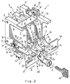
- FIG. 2 shows a schematic perspective illustration of a device for receiving cards with different security.
- the reference numerals 9, 45 and 62 used in this exemplary embodiment correspond analogously to the reference numerals 9, 45, 45 ', 45' ', 62 and 62' used in FIG.
- FIG. 2 schematically shows a device 1 for receiving card-shaped circuit carriers, in particular cards 2, 3 and 4, such as “integrated circuit cards with contacts” according to ISO standard 7816, but also cards with contactless signal coupling, which have different strengths are secured.
- the cards can be designed as so-called memory cards.
- the device 1 has a holder 5 with three sliding guides or frames 6, 7 and 8, which according to FIG. 2 each have a left side wall 11 provided with a recess 10 and are slit-shaped.
- the right side wall 12 (not shown in more detail in FIG. 2) can be designed similarly to the left side wall 11 or a continuous one Have side surface. In the continuous side surface near its rear edge in the direction of insertion, an arcuate recess, not shown, can be provided for better gripping a card.
- the frames 6, 7 and 8 of the holder 5 are connected to one another via a threaded bolt, not shown, which is passed through a bore 14 which is provided on the upper end of each frame in the direction of insertion. Between two frames, a spacer 13 is placed on the threaded bolt, which keeps the frames parallel to one another and at a distance.
- Another threaded bolt can also be provided at the lower end of each frame, which is at the front in the direction of insertion (not shown in more detail) and inserted into a corresponding bore 15.
- the frames of the holder can also be connected to one another at their rear end in the direction of insertion (not shown), such brackets or spacers both at the upper and lower ends of each frame in FIG.
- any number of frames can be connected side by side and parallel to one another to form a compact holder 5.
- the screw connections can also be attached in an area between the front and rear ends of the respective frame in the direction of insertion.
- the cards 2, 3 and 4 are located in the frames 6, 7 and 8, the device 1 also having a locking device 16 designed as a holding device, with the aid of which the cards in FIG the slot-shaped sliding guide are held for the purpose of determining their inserted operating position and secured against removal.
- the locking device 16 has three latches 20, 21, 22, designated overall by 9, each of which can be moved from a locking position blocking the card in its operating position into an unlocking position and vice versa and with the aid of a holding device 23 in its locking position (see FIG ) are held.
- the holding device 23 can also be omitted if the respective bolt consists, for example, of an elastic material and is fixedly connected to its sliding guide or is formed in one piece with it or is held in its locking position due to gravity.
- the latch is preferably attached to the top of the holder.
- Each bolt of the locking device 16 is a lever 20, 21, 22 which extends parallel to the direction of insertion of the card 2, 3, 4 and can be pivoted about a pivot axis 24 in the plane defined by the card plane.
- Each lever 20, 21, 22 is below the frame 6, 7, 8 mounted on the holder 5 such that it is arranged in a recess 25 of the frame, the lower edge 26 of each frame being aligned with the lower edge 27 of the respective lever.
- Each lever 20, 21, 22 has a catch 31 arranged near its free end 30, which engages behind the rear edge 32, 33, 34 of each card 2, 3, 4 in its operating position.
- the locking lug according to the figure encloses the lower corner of each card so that it is secured in its operating position.
- Each locking lug 31 tapers to the free end 30 of the lever 20, 21, 22 and has a corrugation 35 on its side facing the free end of each lever.
- the holding device 23 is a spring 36, one end 37 engages the lever 20 and the other end 38 e.g. can be fastened to the frame 6 of the holder 5, that is to say is supported on the holder 5.
- the holding device 23 designed as a spring 36 is only shown for the left outer lever 20; the other two levers 21, 22 have the same holding device.
- the spring 36 is designed as a torsion spring; but it can also be a tension or compression spring.
- the torsion spring is arranged in the region of the pivot axis 24 of each lever, one pin 37, 38 of the torsion spring supporting one end 37, 38 of the torsion spring being attached to the lever 20, 21, 22 and to the holder 5 or the respective sliding guide.
- the pin attached to each lever can also be an integral plate (see figure).
- the spring ends can also simply be inserted into holes provided on the lever and on the holder.
- a switch 42 is assigned to the lever 20, which detects the locking or unlocking position of the lever and indicates this to a data processing system, not shown.
- the signal emitted by the switch can also be transmitted, for example, to the cash register electronics of a cash register.
- Such a switch can also be assigned to the other levers 21, 22.
- the switch 42 has on its upper side a pivotable bracket 43 which bears against the lower side 27 of the lever 20.
- the bracket 43 is biased towards the lever 20 by means of a torsion spring, not shown.
- the torsion spring of the bracket 43 can also be so strong that it holds the lever in its operating position shown in Figure 2. In this case too, the holding device 23 designed as a spring 36 can be omitted.
- another signaling device for the position of the lever for example a light barrier, can also be provided.
- the switch can be a microswitch which, for example, shows the cash register electronics of a cash register the presence and / or the impending removal of a card.
- a card can, for example, be a user's company ID, e.g. a cashier.
- the locking device 16 is assigned a lockable locking device 44, which according to FIG. 2 acts on two levers 21, 22, with a sliding latch 47 which, from a blocking position preventing movement of the lever in question ( see figure) in a release position releasing a movement of the lever and vice versa.
- a switch similar to switch 42 can be attached to the locking device, which indicates its locked or unlocked state. The switches attached to the bolts 20, 21, 22 can then be omitted.
- a swivel arm provided with a lock is provided, for example, in an embodiment (not shown) which, when the respective bolt is in the locked position, can be moved into or out of its swivel range.
- a swivel arm can be assigned to each individual lever-shaped latch.
- the swivel arm can have a shape which is similar to the swivel arm 46 provided with a lock 45 in FIG. 2.
- the castle is about Region between the free ends of the levers arranged such that the upper edge of the lock is arranged close to the plane passing through the lower edge of the lever.
- the swivel arm In the locked position, the swivel arm is pivoted into the swivel range of the lever held in its locked position such that the swivel arm is now arranged approximately horizontally.
- the locking device 44 comprises the slide lock 47 with a cam profile, each with cams 49 assigned to individual locks 21, 22, which can be moved out of the pivoting range or for unlocking the respective lock when the respective lock is in the locked position.
- the movement of the cam profile 47 takes place via an actuating device 48 designed as a displaceable cam slide, which has the swivel arm 46 provided with the lock 45 and a pin 51 connected to the cam profile 47, on which the swivel arm 46 engages.
- the swivel arm 46 has an elongated recess 50 at its free end, ie opposite the lock 45.
- the elongated recess can also be designed as an elongated hole or guide slot.
- the pin 51 connected to the cam profile 47 engages in the elongated recess 50 of the swivel arm 46.
- a pivoting movement of the pivot arm in the direction of arrow A results in a sliding movement of the pin 51 and thus the cam profile 47 in the direction of the arrow B.
- the sliding movement of the cam profile 47 can be limited by elongated holes 52 which are formed in the sliding bolt and are not shown in the Engage the guide pin.
- the slide bolt 47 is simultaneously arranged and designed to act on the levers 21, 22, the cam profile following the respective cams 49 forming a recess 53, 54, the respective width of which is at least the width of the free end of each bolt (lever ) and the depth of which corresponds at least to the length of engagement of the lever and card or the locking path of the bolt in question, more precisely the length of engagement between the catch 31 and the respective card.
- the cam profile does not act on the left lever 20, so that it operates regardless of the position of the cam profile, i.e. can be pivoted into its unlocked position.
- the cam profile 47 can also be designed to act on all levers, so that in this case three cams 49 and recesses must be provided.
- the locking device 44 can be pivoted transversely to the direction of insertion of the cards (first embodiment) or displaceable (second embodiment), the pivot axis of the swivel arm 46 in the case of the second embodiment being below that of the first embodiment and below the cam profile 47.
- the pivot arm 46 moves in the event of a displacement movement of the cam profile 47 in the direction of the arrow B from a solid position inclined to the left according to the figure, through its top dead center position to a dashed position inclined to the right.
- a further bolt 55 is assigned to the right card 4, which is constructed essentially similar to the bolts designed as levers 20, 21, 22 and is arranged on the holder 5 opposite the lever 22.
- the bolt 55 has in its central region an approximately rectangular projection 56, which is connected to it in one piece and is provided with a through-hole (not shown) and which is located at a short distance from a short leg 57 of an L-shaped angle 60, the short leg 57 of the angle 60 also has a through hole 62 which is aligned with the through hole of the projection 56.
- a locking bolt (not shown) can be inserted into these bores and can be secured against unauthorized removal by a seal.
- the long leg 61 of the angle 60 is non-detachably connected to the holder 5.
- the individual frames of the holder can be formed symmetrically with respect to their longitudinal axis extending in the direction of insertion, so that each frame can also have a recess comparable to the recess 25 at its upper end. Accordingly, pins or pins for holding one end of a spring can also be provided at this end. In conjunction with the spacers 13, this results in a kit for a device for receiving memory cards. It is also possible to provide the levers 20, 21, 22 not on the underside, as shown in the figure, but on the top of the holder (in this position the holding device can be omitted) and the sealed connection between the lever 55 and the angle 60 to attach to the bottom of the holder 5, for example.
- each frame 6, 7, 8 On the bottom and / or top of each frame 6, 7, 8, a vertically extending can between the pivot axis 24 and its end facing the lever Be arranged projection, which can engage in a correspondingly shaped recess of the lever and the vertical pivoting movement of each lever leads such that horizontal displacements in the direction of arrow B or in the opposite direction are excluded.
- contact points or signal transmission elements of the cards and the associated frames have been omitted from the drawing.
- the sealed bolt 55 can be provided on a card which is additionally secured by one of the levers 20, 21, 22, it being possible to also secure one of these last-mentioned levers by the locking device 44.
- the further bolt 55 with the lead seal 62 can also be provided on a memory card which is locked only with the aid of a lever, such as the lever 20, which is not additionally secured by the locking device 44.
- the locking device like the bolts or levers, can also be arranged on the top of the holder.
- the individual levers 20, 21, 22 can be fastened to the holder 5 in the region of their pivot axis 24, for example with a bolt secured in a conventional manner.
- the slide bolt 47 with the cam profile is adjusted via a key 63 and the lock bolt 46 in the direction of arrow B until the lever 22 can also be adjusted from its locking position shown in FIG. 2 to its unlocking position.
- the further bolt 55 has not yet been sealed with the angle 60.
- the card 4 is then inserted into the frame 8 of the holder 5, the lever 22 and the latch 55 in their respective unlocked position can be pivoted. When the card 4 is fully inserted, the lever 22 or the latch 55 snap back and thus fix their locking position. Now the other bolt 55 can be sealed by an authorized person.
- the card 3 is inserted into the sliding guide of the frame 7 until the lever 21 snaps back into its locking position.
- the cam profile and the swivel arm 46 shown in broken lines is moved in the direction of arrow C, i.e. moved to the left until the recesses 53, 54 adjacent to the cams 49 are arranged between the individual levers.
- the respective cams 49 are now arranged directly below the lower edge of the levers 21 and 22, so that a pivoting movement of these levers into their unlocked position is not possible.
- the key 63 can now be removed and given to a supervisor.
- the memory card 2 can be inserted into the sliding guide of the frame 6 at any time and can be pulled out of the latter by a downward pressure on the free end of the lever 20 in order to overcome the force of the holding device 23.
- This exemplary embodiment thus shows cards that are secured to different degrees.
- Such an arrangement is preferably used in cash registers, the card which is not secured against removal by the blocking device 44 representing, for example, the company ID of the cashier (company card).
- the cashier uses this card to register at the cash register and uses the integrated cards on the card Circuits the cash register's operational functions in motion. During the checkout process, the statements made by the cashier in question are then saved on the card.
- the second sliding guide 7 can be used to hold, for example, the managing director's card. Information such as the order of the cashiers, daily turnover etc. is recorded on it.
- This card can only be removed if the locking device can be moved into its release position using a special key. The key is therefore only given to the managing director.
- the third slot-shaped guide 8 is used to hold e.g. a "memory fiscal card" which can only be removed by opening the sealing device 62 and, if this also acts on the locking device for the memory fiscal card, by moving the locking device.
- the sealing can be carried out by authorized authorities, e.g. the tax office. It is clear that different information can be stored on the individual cards or different information or signals can be emitted from the individual cards to a system processing these signals.
- the cash drawer 201 essentially consists of a cash drawer 203 which is displaceably guided in a drawer housing 202 in the direction of extension and retraction (see arrows A, B in FIG. 4) and which is arranged and designed in such a way that it can be opened before the cash register is operated, i.e. in front of each work unit, can be inserted into the shop housing 202 and after the cash register has been operated, i.e. after each work unit, can be removed from the shop housing 202.
- the cash drawer 203 is supported on a holder 204 which partially encompasses the cash drawer.
- the holder is a U-shaped profile, into which the cash drawer 203 is inserted or inserted.
- the holder 204 is connected in a manner not shown in more detail to guide rails which are fastened in the drawer housing 202 and enable the holder and the cash drawer connected to it to be displaced in the direction of extension and retraction (see arrows A and B in FIG. 4).
- the bottom wall 205 has a recess 206 in its outside facing downward in FIG.
- the cash drawer 203 has a cover 214 which can be moved between a closed position (see FIG. 4) closing the cash drawer 203 and a release position (see also FIG. 3) and in its closed position with the Cash drawer 203 is releasably locked.
- the cover 214 is guided displaceably on the cash drawer 203 by means of a sliding guide 215 and can be locked with the cash drawer 203 by means of a locking device 210 (cf. FIG. 4).
- the sliding guide 215 consists of an L-shaped profile 221 attached to the underside 220 of the cover 214 near each side edge 216, 217 of the cover 214, which engages around a web 224 formed on the upper end of each side wall 222, 223 of the cash drawer 203.
- the webs 224 begin near the rear wall 207 and end by a dimension 225 in front of the front wall 226 of the cash drawer 203 in the entry direction B.
- the webs 224 and those described below are Elements 210, 211, 212 are not attached to the cash drawer 203 but to the money insert. The exemplary embodiment with the use of money is no longer discussed below.
- the lid 214 can be locked with the drawer housing 202 with the aid of a latching device 227 when the cash drawer 203 is fully inserted into the drawer housing 202 (cf. FIG. 4) and has a lock 230 which allows the cash drawer 203 to be pulled out completely when the lid is connected to the drawer housing 202 214 prevented.
- the latching device 227 is a latching lever 232 which extends parallel to the direction of movement (see arrows A and B in FIG. 4) of the cover 214 and can be pivoted in the cover plane about a pivot axis 231 mounted on the cover and which has a spring 233 in its locking position shown in Fig. 3, i. H. clockwise, is biased.
- the latching lever 232 is connected to the cover 214 approximately in its longitudinal center via the pivot axis 231.
- the spring 233 is a torsion spring which is arranged in the region of the pivot axis 231 and one end 234 of which engages with the locking lever 232 and the other end 235 of which is supported on the cover 214 by means of a pin 236.
- the spring can also be a tension or compression spring supported at one end of the latching lever 232.
- the locking lever 232 is elongated and extends on the underside 220 of the cover 214 almost over its entire length.
- the locking lever is surrounded by a channel-shaped cover 237, which is attached to the underside 220 of the cover 214 and itself extends from the front end 240 of the lid to close to the lid rear edge 241.
- the front end 240 of the locking lever 232 in the insertion direction of the cover 214 has a locking lug 242 which, in the position of the cover 214 pushed into the drawer housing 202 (see FIG. 4), engages behind a pin 243 held on the drawer housing 202.
- the cover 214 In the area of the locking lug 242 of the locking lever 232, the cover 214 has a recess 244 in which the pin 243 is located when the cover is fully inserted into the drawer housing 202.
- the locking device 210 is attached to the rear wall 207 of the cash drawer 203 in the entry direction (see arrow B in FIG. 4).
- the locking device 210 is a lock bolt 212 provided with a lock 11, which can be moved between a locking position blocking a movement of the cover 214 and an unlocking position releasing such a movement.
- the lock bolt 212 of the locking device 210 can engage in a recess in the rear region of the cover 214 (not shown in more detail) when the lock 211 is rotated by means of a key 213 by approximately 90 ° (see arrow C in FIG. 3) ( Dashed illustration of the lock bolt 212) pivoted upward in FIG. 3 or engage behind the lock 230.
- the rear end 245 of the locking lever 232 in the insertion direction extends up to close to the rear edge 241 of the lid.
- the locking device 210 is arranged and designed to act on the rear end 245 of the locking lever 232, so that the lock bolt 212 in its according to arrow C upward pivoted locking position (shown in dashed lines in FIG. 3) can act on the rear end 245 of the locking lever 232 (see arrow D in FIG. 3).
- the rear end 245 of the locking lever 232 projects beyond the rear end 246 of the channel-shaped cover 237 by a small amount. This dimension corresponds at least to the thickness of the lock bolt 212.
- the lid rear edge 241 is partially designed as a lock 230 bent toward the cash drawer 203, the width of which is greater than the distance between the lid 214 and the upper edge of the money drawer 203.
- the lid trailing edge 241 in the area of the sliding guide 215 does not bend towards the cash drawer, but rather serves as a stop against the rear wall 207 of the cash drawer 203 when the cover 214 is guided on the cash drawer 203.
- the front wall 226 of the cash drawer 203 has one at its upper end in FIG. 3 Recess 247, the length and depth of which correspond at least to the corresponding sizes of the channel-shaped cover 237.
- the cash drawer 203 can be locked in its position pushed into the drawer housing 202 by means of the locking device 210 with the drawer housing 202.
- the lock bolt 212 of the locking device 210 can engage, for example, in a recess, not shown, in the underside of the upper wall of the shop housing 202.
- the cover 214 has a receiving compartment 250 for card-shaped circuit carriers, in particular cards (not shown in greater detail) with integrated circuits, mainly near its front end 240 according to ISO standard 7816, wherein the receiving compartment 50 has a cover 252 which is pivotably mounted on the upper side 251 of the cover 214 and which can be closed with the cover 214 by means of a lock 253 (see FIG. 5).
- the cover 252 is L-shaped, with one leg 254 of this L-profile extending in the vertical direction and receiving the lock 253.
- the side edge 216 is angled, bent downward in FIG. 5 and has an opening 255 for the lock bolt of the lock 253, which is not shown in detail.
- the cover 252 can be used to hold a card (not shown) in the Receiving compartment 250 is pivoted in the direction of arrow E about its pivot axis 256 and can be blocked by means of a key 257 and the lock 253 when the cover 252 is arranged parallel to the upper side 251.
- the receptacle 250 When the cover 252 is closed, the receptacle 250 has at its end 260 near the front end 240 of the cover 214 a slot, not shown, whose width is less than the thickness of the card arranged in the receptacle, but is so large that contact elements or signal transmission elements are one Not shown in detail, arranged in the drawer housing 202 pin strip through the slot of the receiving compartment 250 can engage in a contact formed at the front end of the card contact the card. When the lid 214 guided on the cash drawer 203 is inserted into the shop housing 202, the contact elements automatically contact the respective contacting of the card.
- the cards can be designed as so-called memory cards and can contain, for example, the data of the cashier and the daily turnover achieved at the cash register in question.
- the change content of the cash drawer 203 and the working hours of the checkout staff can be stored on the card.
- the card can also be a simple memory card for storing information.
- the card is preferably a chip card (card with integrated circuits), which interact with the control of the cash register and, for example, switch on the operating functions of the cash register, etc.
- a card-shaped circuit carrier e.g. a card with integrated circuits is inserted into the receiving compartment 250 located on the top 251 of the cover 214 in such a way that the contacting of the card points to the end 260 of the receiving compartment.
- the cover 252 of the storage compartment 250 is pivoted in the direction of arrow E (see FIG. 5) until the lock bolt, not shown, of the lock 253 engages in the opening 255 and can be rotated using the key 257 so that the storage compartment is locked and the card inside is secured against removal.
- the lid 214 is now placed on the cash drawer 203 in such a way that the lid rear edge 241 is approximately in the area of the dimension 225, that is to say between the front end of the sliding guide 215 and the front wall 226 of the cash drawer 203.
- the L-shaped profile 221 does not yet engage the webs 224 of the sliding guide 215.
- the rear end 246 of the channel-shaped cover 237 is already approximately in the region of the recess 247 formed in the front wall 226 of the cash drawer 203.
- cover 214 can also change in the cash drawer is inserted.
- the cover is then moved in the direction of arrow F (see FIG. 3) until the rear edge 241 of the cover, which has not been bent over, strikes against the rear wall 207 of the cash drawer.
- the lock bolt 212 can be pivoted from its position shown in FIG. 3 with the help of the key 213 in the direction of arrow C until the free end of the lock bolt 212 engages behind the rear edge of the lid, which is designed as a lock 230.
- the lock 211 can be designed such that the key 213 can also be withdrawn from the cash drawer 203 in this position, which preferably does not act on the locking lever 232. In this position, the lid is in its locked position and is locked with the cash drawer 203.
- Such a cash drawer can be handed over to a person of the cashier's staff, who preferably places it on the holder 204 of a cash register (not shown) from above such that the holder comes to rest in the recess 206 provided in the bottom wall 205.
- the cash drawer 203 with its cover 214, including the holder 204 is inserted into the drawer housing 202 (cf.running-in direction according to arrow B in FIG. 4) until the latching lever 232 first performs a pivoting movement in the counterclockwise direction, then clockwise about its pivot axis 231 and engages behind the pin 243 held in the drawer housing 202. 4, the cash drawer is fully inserted into the drawer housing 202 in this position.
- the cash drawer only partially fits into the drawer housing 202 when the cover 214 is locked in place is inserted. It is also conceivable to lock the money insert instead of the drawer housing with the cash drawer which is firmly mounted on the cash register.
- the lock bolt 212 is brought into its solid position shown in FIG. 3 and the cash drawer 203 for a sliding movement in the direction of extension and retraction (see arrows A, B in FIG 4) released.
- the contact elements of a pin strip not shown, engage in one or more contact receptacles of the relevant card corresponding to the contact elements, so that the cash register is ready for the person concerned.
- the cash register is then operated as in a conventional manner.
- the rear lid edge 241 which is designed as a lock 230 and is bent in the direction of the cash drawer 230, prevents the cash drawer from being pulled out completely from the drawer housing without the lid 214.
- the cash drawer After the cash register has been operated for the personnel concerned, that is to say also when the cashier changes, the cash drawer is pushed completely into the shop housing and, with the help of the key 213, pivots the lock bolt 212 in the direction of arrow C as far as the one in FIG. 3 Dashed position shown, in which the lock bolt acts on the rear end 245 of the locking lever 232 in the direction of arrow D against the force of the spring 233, so that the locking lever 232 moves counterclockwise about the pivot axis 231 and the locking lug 242 Pin 43 releases.
- the cash drawer 203 together with its cover 214 and the holder 204 can now be pulled out of the drawer housing 202 of the cash register.
- the key 213 is preferably removed beforehand from the rear wall 207 of the cash drawer, it being possible for the lock bolt to pivot a small amount against the direction of the arrow C due to the force of the spring 233 and the key only in this position of the lock bolt 212 can be deducted. But it is also possible that the key 213 can be removed in the dashed position of the lock bolt 212; in this case the latching lever 232 can be biased against the lock bolt.
- the cash drawer When the holder 204 is completely pulled out of the drawer housing 202, the cash drawer, with its cover located in the locked position, is lifted out of the holder 204 and stored in a safe place. Simultaneously with the pulling out of the cash drawer with the associated lid, the contact elements also become disengaged from the card, so that the cashier in question automatically logs off from the cash register.
- a cash drawer designed in this way is simple and helps to avoid accounting inconsistencies.
- the cash drawer described above can be used particularly advantageously if it is assigned to a specific person of the cashier. Each person in the checkout staff is then assigned a separate cash drawer that is operated exclusively by this person. When the checkout staff changes, one person removes their cash drawer from the shop case, while the other person inserts their own money drawer into the shop case. In the Any errors in individual cash drawers that have been noticed in the cash register can therefore be easily assigned to the person concerned, so that there can be less inconsistencies in personnel in particular if several people have operated the cash register during a work unit. If the cashier staff changes frequently, so-called jumping, billing errors that occur, for example when changing the change from the cash drawer of a cash register, can no longer lead to inconsistencies between the individual staff of the cashier staff.
Landscapes
- Physics & Mathematics (AREA)
- General Physics & Mathematics (AREA)
- Engineering & Computer Science (AREA)
- Theoretical Computer Science (AREA)
- Business, Economics & Management (AREA)
- Computer Networks & Wireless Communication (AREA)
- Microelectronics & Electronic Packaging (AREA)
- Accounting & Taxation (AREA)
- Strategic Management (AREA)
- General Business, Economics & Management (AREA)
- Cash Registers Or Receiving Machines (AREA)
- Storage Device Security (AREA)
- Power Sources (AREA)
Abstract
Claims (13)
- Appareil commandable par un ordinateur, comprenant au moins un dispositif de réception agencé pour recevoir une carte à puce (100) et comportant un dispositif de contact (110, 114) pour relier une carte à puce (100) à d'autres composants de l'appareil, caractérisé par le fait que l'ordinateur est formé par une carte à puce (100) contenant au moins une unité centrale à processeur (CPU), une mémoire de lecture (ROM), une mémoire de travail (RAM) et un module d'entrée/sortie (module I/O), que l'appareil possède un système électronique de puissance et d'attaque (118) installé de façon fixe et une unité d'alimentation en courant (130) installée de façon fixe, et que le dispositif de contact comprend des contacts de liaison (110) servant à réunir le module (I/O) au système électronique de puissance et d'attaque (118).
- Appareil suivant la revendication 1, caractérisé par le fait que l'appareil comporte d'autres dispositifs de réception permettant de loger d'autres cartes à puce (132, 134, 138), qui coopèrent avec la carte à puce formant ordinateur (100), et que ces cartes comportent d'autres dispositifs de réception pourvus de dispositifs de contact (117, 119; 121, 123), qui sont reliés au dispositif de réception de la carte à puce formant ordinateur (100).
- Appareil suivant la revendication 1 ou 2, caractérisé par le fait qu'à l'appareil peuvent être raccordés des dispositifs périphériques (120, 122, 124) coopérant avec ledit appareil et qu'au moins des dispositifs individuels de réception pour respectivement l'une (138) des autres cartes à puces comportent un dispositif de contact (125, 127), qui est raccordé directement à un dispositif périphérique (120).
- Appareil suivant l'une des revendications 1 à 3, caractérisé par le fait qu'aux dispositifs de réception sont associés des moyens (9, 45, 62) servant à empêcher tout retrait des cartes à puces (100, 132, 134, 138) respectivement enfichées.
- Appareil suivant la revendication 4, caractérisé par le fait que des moyens de blocage (9, 45, 62) appliquant des forces différentes, sont associés à différents dispositifs de réception.
- Appareil suivant l'une des revendications 1 à 5, caractérisé par le fait qu'il est agencé à la manière d'une caisse enregistreuse et que l'une (132) des autres cartes à puce porte des données pour identifier et signaler un caissier et pour activer la fonction de service de la caisse enregistreuse (carte de société).
- Appareil suivant la revendication 6, caractérisé par le fait que l'une (134) des autres cartes à puce porte des données servant à identifier un gérant de rang supérieur à celui des caissiers et est agencée de manière à mémoriser et traiter des données concernant le directeur (carte de gérant).
- Appareil suivant les revendications 6 et 7, caractérisé par le fait que l'une (138) des autres cartes à puce portent et mémorisent des données importantes du point de vue fiscal (Memory fiscale).
- Appareil suivant l'une des revendications 6 à 8, caractérisé par le fait qu'il est prévu un porte-cartes (5) comportant plusieurs dispositifs de réception (6, 7, 8) et qu'à chaque casier récepteur est associé un dispositif de verrouillage (20, 21, 22) servant à maintenir une carte enfichée (2, 3, 4) dans sa position enfichée.
- Appareil suivant la revendication 9, caractérisé par le fait qu'un dispositif de blocage (44), équipé d'un dispositif de fermeture (45), est prévu pour le blocage des dispositifs de verrouillage (20, 21, 22) dans leur position verrouillée.
- Appareil suivant la revendication 10, caractérisé par le fait que le dispositif de blocage comporte plusieurs organes de blocage individuels indépendants (44, 61), qui servent à bloquer des dispositifs de verrouillage déterminés (22, 55).
- Appareil suivant l'une des revendications 6 à 11, comportant un tiroir-caisse, caractérisé par le fait qu'un dispositif de réception (250) est formé dans le tiroir-caisse (201).
- Appareil suivant la revendication 12, caractérisé par le fait que le tiroir-caisse (201) est équipé d'un couvercle (214), qui subsiste dans le logement de la caisse lorsque le tiroir-caisse est ressorti, le casier récepteur (250) étant formé sur le couvercle.
Priority Applications (1)
| Application Number | Priority Date | Filing Date | Title |
|---|---|---|---|
| AT91916577T ATE104079T1 (de) | 1990-09-26 | 1991-09-26 | Durch einen rechner steuerbares geraet. |
Applications Claiming Priority (5)
| Application Number | Priority Date | Filing Date | Title |
|---|---|---|---|
| DE4030455 | 1990-09-26 | ||
| DE4030456A DE4030456C1 (fr) | 1990-09-26 | 1990-09-26 | |
| DE4030456 | 1990-09-26 | ||
| DE4030455A DE4030455A1 (de) | 1990-09-26 | 1990-09-26 | Vorrichtung zum aufnehmen von karten mit integrierten schaltkreisen |
| PCT/EP1991/001832 WO1992005520A1 (fr) | 1990-09-26 | 1991-09-26 | Appareil commande par ordinateur |
Publications (2)
| Publication Number | Publication Date |
|---|---|
| EP0550514A1 EP0550514A1 (fr) | 1993-07-14 |
| EP0550514B1 true EP0550514B1 (fr) | 1994-04-06 |
Family
ID=25897220
Family Applications (1)
| Application Number | Title | Priority Date | Filing Date |
|---|---|---|---|
| EP91916577A Expired - Lifetime EP0550514B1 (fr) | 1990-09-26 | 1991-09-26 | Appareil commande par ordinateur |
Country Status (7)
| Country | Link |
|---|---|
| EP (1) | EP0550514B1 (fr) |
| JP (1) | JPH06501326A (fr) |
| KR (1) | KR930702731A (fr) |
| DE (1) | DE59101336D1 (fr) |
| ES (1) | ES2051133T3 (fr) |
| HK (1) | HK131595A (fr) |
| WO (1) | WO1992005520A1 (fr) |
Families Citing this family (2)
| Publication number | Priority date | Publication date | Assignee | Title |
|---|---|---|---|---|
| EP0700562A4 (fr) * | 1993-03-08 | 1998-12-02 | Voice It Worldwide Inc Walters | Dispositif d'enregistrement et de reproduction sonores ayant la taille d'une carte de credit |
| IT1277955B1 (it) * | 1995-12-22 | 1997-11-12 | Italdata S R L | Sistema di sicurezza per il riconoscimento di dati, in particolare identita' personale |
Family Cites Families (6)
| Publication number | Priority date | Publication date | Assignee | Title |
|---|---|---|---|---|
| DE2840980C3 (de) * | 1977-10-08 | 1982-05-06 | Tokyo Electric Co., Ltd., Tokyo | Elektronische Registrierkasse und elektronisches Registrierknensystem |
| FR2448826A1 (fr) * | 1979-02-06 | 1980-09-05 | Telediffusion Fse | Carte d'abonnement pour recepteur de videotex et poste de chargement de ladite carte |
| EP0072370B1 (fr) * | 1981-08-14 | 1988-06-22 | Control Commerce AG | Tiroir-caisse pour caisses enregistreuses de guichets, comptoirs ou analogues |
| EP0247623A3 (en) * | 1984-03-19 | 1989-09-20 | Omron Tateisi Electronics Co. | Ic card transaction system |
| JPH02111861U (fr) * | 1989-02-27 | 1990-09-06 | ||
| JPH02235663A (ja) * | 1989-03-08 | 1990-09-18 | Canon Inc | 出力装置に装着可能な文字パターン発生装置 |
-
1991
- 1991-09-26 DE DE91916577T patent/DE59101336D1/de not_active Expired - Fee Related
- 1991-09-26 WO PCT/EP1991/001832 patent/WO1992005520A1/fr not_active Ceased
- 1991-09-26 ES ES91916577T patent/ES2051133T3/es not_active Expired - Lifetime
- 1991-09-26 EP EP91916577A patent/EP0550514B1/fr not_active Expired - Lifetime
- 1991-09-26 JP JP3514928A patent/JPH06501326A/ja active Pending
- 1991-09-26 KR KR1019930700935A patent/KR930702731A/ko not_active Withdrawn
-
1995
- 1995-08-17 HK HK131595A patent/HK131595A/xx unknown
Also Published As
| Publication number | Publication date |
|---|---|
| DE59101336D1 (de) | 1994-05-11 |
| ES2051133T3 (es) | 1994-06-01 |
| JPH06501326A (ja) | 1994-02-10 |
| EP0550514A1 (fr) | 1993-07-14 |
| HK131595A (en) | 1995-08-24 |
| WO1992005520A1 (fr) | 1992-04-02 |
| KR930702731A (ko) | 1993-09-09 |
Similar Documents
| Publication | Publication Date | Title |
|---|---|---|
| DE69834236T2 (de) | Karteneinführmechnismus | |
| DE2528537B2 (de) | Bargeldverteilervorrichtung für Banken oder Kreditinstitute | |
| DE2949344A1 (de) | Kassette fuer flexible blaetter | |
| DE69313855T2 (de) | Magnetische schlösser | |
| EP1205875B1 (fr) | Dispositif de réception de carte à puce | |
| EP2465099B1 (fr) | Contenant pour recevoir des billets et procédé pour fermer un contenant, comprenant une partie boîtier et un couvercle, destiné à recevoir des billets | |
| DE4030455A1 (de) | Vorrichtung zum aufnehmen von karten mit integrierten schaltkreisen | |
| EP0014856A1 (fr) | Conteneur d'argent pour des caisses enregistreuses | |
| EP0550514B1 (fr) | Appareil commande par ordinateur | |
| EP0212165B2 (fr) | Machine de vente avec cassette à pièces de monnaie interchangeable | |
| DE3310656C1 (de) | Transportable registrierkassengesteuerte Geldkassette | |
| DE8803573U1 (de) | Kundenservice-Terminal | |
| DE69831311T2 (de) | Kartenschloss | |
| DE3309462C2 (de) | Türanordnung für das Bedienungsfeld eines Gerätes | |
| DE20208183U1 (de) | Vorrichtung zur Sicherung von Notausgangstüren | |
| EP0838567B1 (fr) | Serrure électrique de coffre-fort | |
| DE2912253A1 (de) | Schliessfach mit rueckseitig angeordnetem schloss | |
| DE9101306U1 (de) | Foyer-Zugangskontrolleser | |
| DE3314882A1 (de) | Schliessvorrichtung zum verriegeln von tueren | |
| DE3874089T2 (de) | Muenzbetaetigte vorrichtung. | |
| EP1317595B1 (fr) | Systeme de fermeture pour boitiers | |
| DE102024110580A1 (de) | Geldkassette mit Verriegelungsmechanismus | |
| DE19544519C1 (de) | Schwenkbare Halterung für einen Gegenstand, insbesondere ein Sichtgerät | |
| DE112005003579B4 (de) | Pfandschloss | |
| DE102024116122A1 (de) | Warenverkaufsautomat |
Legal Events
| Date | Code | Title | Description |
|---|---|---|---|
| PUAI | Public reference made under article 153(3) epc to a published international application that has entered the european phase |
Free format text: ORIGINAL CODE: 0009012 |
|
| 17P | Request for examination filed |
Effective date: 19930204 |
|
| AK | Designated contracting states |
Kind code of ref document: A1 Designated state(s): AT BE CH DE ES FR GB IT LI NL SE |
|
| 17Q | First examination report despatched |
Effective date: 19930812 |
|
| GRAA | (expected) grant |
Free format text: ORIGINAL CODE: 0009210 |
|
| AK | Designated contracting states |
Kind code of ref document: B1 Designated state(s): AT BE CH DE ES FR GB IT LI NL SE |
|
| REF | Corresponds to: |
Ref document number: 104079 Country of ref document: AT Date of ref document: 19940415 Kind code of ref document: T |
|
| REF | Corresponds to: |
Ref document number: 59101336 Country of ref document: DE Date of ref document: 19940511 |
|
| REG | Reference to a national code |
Ref country code: ES Ref legal event code: FG2A Ref document number: 2051133 Country of ref document: ES Kind code of ref document: T3 |
|
| ITF | It: translation for a ep patent filed | ||
| GBT | Gb: translation of ep patent filed (gb section 77(6)(a)/1977) |
Effective date: 19940614 |
|
| ET | Fr: translation filed | ||
| EAL | Se: european patent in force in sweden |
Ref document number: 91916577.9 |
|
| PLBE | No opposition filed within time limit |
Free format text: ORIGINAL CODE: 0009261 |
|
| STAA | Information on the status of an ep patent application or granted ep patent |
Free format text: STATUS: NO OPPOSITION FILED WITHIN TIME LIMIT |
|
| 26N | No opposition filed | ||
| PGFP | Annual fee paid to national office [announced via postgrant information from national office to epo] |
Ref country code: CH Payment date: 19971217 Year of fee payment: 7 |
|
| PGFP | Annual fee paid to national office [announced via postgrant information from national office to epo] |
Ref country code: AT Payment date: 19980826 Year of fee payment: 8 |
|
| PGFP | Annual fee paid to national office [announced via postgrant information from national office to epo] |
Ref country code: SE Payment date: 19980909 Year of fee payment: 8 Ref country code: BE Payment date: 19980909 Year of fee payment: 8 |
|
| PGFP | Annual fee paid to national office [announced via postgrant information from national office to epo] |
Ref country code: NL Payment date: 19980921 Year of fee payment: 8 |
|
| PG25 | Lapsed in a contracting state [announced via postgrant information from national office to epo] |
Ref country code: LI Free format text: LAPSE BECAUSE OF NON-PAYMENT OF DUE FEES Effective date: 19980930 Ref country code: CH Free format text: LAPSE BECAUSE OF NON-PAYMENT OF DUE FEES Effective date: 19980930 |
|
| REG | Reference to a national code |
Ref country code: CH Ref legal event code: PL |
|
| PG25 | Lapsed in a contracting state [announced via postgrant information from national office to epo] |
Ref country code: AT Free format text: LAPSE BECAUSE OF NON-PAYMENT OF DUE FEES Effective date: 19990926 |
|
| PG25 | Lapsed in a contracting state [announced via postgrant information from national office to epo] |
Ref country code: SE Free format text: THE PATENT HAS BEEN ANNULLED BY A DECISION OF A NATIONAL AUTHORITY Effective date: 19990929 |
|
| PG25 | Lapsed in a contracting state [announced via postgrant information from national office to epo] |
Ref country code: BE Free format text: LAPSE BECAUSE OF NON-PAYMENT OF DUE FEES Effective date: 19990930 |
|
| BERE | Be: lapsed |
Owner name: SIEMENS NIXDORF INFORMATIONSSYSTEME A.G. Effective date: 19990930 |
|
| PG25 | Lapsed in a contracting state [announced via postgrant information from national office to epo] |
Ref country code: NL Free format text: LAPSE BECAUSE OF NON-PAYMENT OF DUE FEES Effective date: 20000401 |
|
| EUG | Se: european patent has lapsed |
Ref document number: 91916577.9 |
|
| NLV4 | Nl: lapsed or anulled due to non-payment of the annual fee |
Effective date: 20000401 |
|
| PGFP | Annual fee paid to national office [announced via postgrant information from national office to epo] |
Ref country code: ES Payment date: 20000724 Year of fee payment: 10 |
|
| REG | Reference to a national code |
Ref country code: GB Ref legal event code: 732E |
|
| PGFP | Annual fee paid to national office [announced via postgrant information from national office to epo] |
Ref country code: FR Payment date: 20000921 Year of fee payment: 10 |
|
| PGFP | Annual fee paid to national office [announced via postgrant information from national office to epo] |
Ref country code: GB Payment date: 20000922 Year of fee payment: 10 |
|
| PGFP | Annual fee paid to national office [announced via postgrant information from national office to epo] |
Ref country code: DE Payment date: 20000926 Year of fee payment: 10 |
|
| REG | Reference to a national code |
Ref country code: FR Ref legal event code: TP |
|
| PG25 | Lapsed in a contracting state [announced via postgrant information from national office to epo] |
Ref country code: GB Free format text: LAPSE BECAUSE OF NON-PAYMENT OF DUE FEES Effective date: 20010926 |
|
| PG25 | Lapsed in a contracting state [announced via postgrant information from national office to epo] |
Ref country code: ES Free format text: LAPSE BECAUSE OF NON-PAYMENT OF DUE FEES Effective date: 20010927 |
|
| REG | Reference to a national code |
Ref country code: GB Ref legal event code: IF02 |
|
| PG25 | Lapsed in a contracting state [announced via postgrant information from national office to epo] |
Ref country code: DE Free format text: LAPSE BECAUSE OF NON-PAYMENT OF DUE FEES Effective date: 20020501 |
|
| GBPC | Gb: european patent ceased through non-payment of renewal fee |
Effective date: 20010926 |
|
| PG25 | Lapsed in a contracting state [announced via postgrant information from national office to epo] |
Ref country code: FR Free format text: LAPSE BECAUSE OF NON-PAYMENT OF DUE FEES Effective date: 20020531 |
|
| REG | Reference to a national code |
Ref country code: FR Ref legal event code: ST |
|
| REG | Reference to a national code |
Ref country code: ES Ref legal event code: FD2A Effective date: 20021011 |
|
| PG25 | Lapsed in a contracting state [announced via postgrant information from national office to epo] |
Ref country code: IT Free format text: LAPSE BECAUSE OF NON-PAYMENT OF DUE FEES;WARNING: LAPSES OF ITALIAN PATENTS WITH EFFECTIVE DATE BEFORE 2007 MAY HAVE OCCURRED AT ANY TIME BEFORE 2007. THE CORRECT EFFECTIVE DATE MAY BE DIFFERENT FROM THE ONE RECORDED. Effective date: 20050926 |