EP0550813A1 - Rohrkupplung - Google Patents
Rohrkupplung Download PDFInfo
- Publication number
- EP0550813A1 EP0550813A1 EP92119104A EP92119104A EP0550813A1 EP 0550813 A1 EP0550813 A1 EP 0550813A1 EP 92119104 A EP92119104 A EP 92119104A EP 92119104 A EP92119104 A EP 92119104A EP 0550813 A1 EP0550813 A1 EP 0550813A1
- Authority
- EP
- European Patent Office
- Prior art keywords
- clamping
- housing
- tensioning
- screw
- pipe coupling
- Prior art date
- Legal status (The legal status is an assumption and is not a legal conclusion. Google has not performed a legal analysis and makes no representation as to the accuracy of the status listed.)
- Granted
Links
Images
Classifications
-
- F—MECHANICAL ENGINEERING; LIGHTING; HEATING; WEAPONS; BLASTING
- F16—ENGINEERING ELEMENTS AND UNITS; GENERAL MEASURES FOR PRODUCING AND MAINTAINING EFFECTIVE FUNCTIONING OF MACHINES OR INSTALLATIONS; THERMAL INSULATION IN GENERAL
- F16L—PIPES; JOINTS OR FITTINGS FOR PIPES; SUPPORTS FOR PIPES, CABLES OR PROTECTIVE TUBING; MEANS FOR THERMAL INSULATION IN GENERAL
- F16L21/00—Joints with sleeve or socket
-
- F—MECHANICAL ENGINEERING; LIGHTING; HEATING; WEAPONS; BLASTING
- F16—ENGINEERING ELEMENTS AND UNITS; GENERAL MEASURES FOR PRODUCING AND MAINTAINING EFFECTIVE FUNCTIONING OF MACHINES OR INSTALLATIONS; THERMAL INSULATION IN GENERAL
- F16L—PIPES; JOINTS OR FITTINGS FOR PIPES; SUPPORTS FOR PIPES, CABLES OR PROTECTIVE TUBING; MEANS FOR THERMAL INSULATION IN GENERAL
- F16L17/00—Joints with packing adapted to sealing by fluid pressure
- F16L17/02—Joints with packing adapted to sealing by fluid pressure with sealing rings arranged between outer surface of pipe and inner surface of sleeve or socket
- F16L17/04—Joints with packing adapted to sealing by fluid pressure with sealing rings arranged between outer surface of pipe and inner surface of sleeve or socket with longitudinally split or divided sleeve
-
- F—MECHANICAL ENGINEERING; LIGHTING; HEATING; WEAPONS; BLASTING
- F16—ENGINEERING ELEMENTS AND UNITS; GENERAL MEASURES FOR PRODUCING AND MAINTAINING EFFECTIVE FUNCTIONING OF MACHINES OR INSTALLATIONS; THERMAL INSULATION IN GENERAL
- F16L—PIPES; JOINTS OR FITTINGS FOR PIPES; SUPPORTS FOR PIPES, CABLES OR PROTECTIVE TUBING; MEANS FOR THERMAL INSULATION IN GENERAL
- F16L21/00—Joints with sleeve or socket
- F16L21/002—Sleeves or nipples for pipes of the same diameter; Reduction pieces
- F16L21/005—Sleeves or nipples for pipes of the same diameter; Reduction pieces made of elastic material, e.g. partly or completely surrounded by clamping devices
-
- F—MECHANICAL ENGINEERING; LIGHTING; HEATING; WEAPONS; BLASTING
- F16—ENGINEERING ELEMENTS AND UNITS; GENERAL MEASURES FOR PRODUCING AND MAINTAINING EFFECTIVE FUNCTIONING OF MACHINES OR INSTALLATIONS; THERMAL INSULATION IN GENERAL
- F16L—PIPES; JOINTS OR FITTINGS FOR PIPES; SUPPORTS FOR PIPES, CABLES OR PROTECTIVE TUBING; MEANS FOR THERMAL INSULATION IN GENERAL
- F16L21/00—Joints with sleeve or socket
- F16L21/08—Joints with sleeve or socket with additional locking means
-
- F—MECHANICAL ENGINEERING; LIGHTING; HEATING; WEAPONS; BLASTING
- F16—ENGINEERING ELEMENTS AND UNITS; GENERAL MEASURES FOR PRODUCING AND MAINTAINING EFFECTIVE FUNCTIONING OF MACHINES OR INSTALLATIONS; THERMAL INSULATION IN GENERAL
- F16L—PIPES; JOINTS OR FITTINGS FOR PIPES; SUPPORTS FOR PIPES, CABLES OR PROTECTIVE TUBING; MEANS FOR THERMAL INSULATION IN GENERAL
- F16L55/00—Devices or appurtenances for use in, or in connection with, pipes or pipe systems
- F16L55/16—Devices for covering leaks in pipes or hoses, e.g. hose-menders
- F16L55/168—Devices for covering leaks in pipes or hoses, e.g. hose-menders from outside the pipe
- F16L55/17—Devices for covering leaks in pipes or hoses, e.g. hose-menders from outside the pipe by means of rings, bands or sleeves pressed against the outside surface of the pipe or hose
- F16L55/172—Devices for covering leaks in pipes or hoses, e.g. hose-menders from outside the pipe by means of rings, bands or sleeves pressed against the outside surface of the pipe or hose the ring, band or sleeve being tightened by a tangentially arranged threaded pin and a nut
Definitions
- the present invention relates to a pipe coupling according to the preamble of claim 1.
- Pipe couplings of this type are known from DE-A-24 28 101 (or the corresponding US-A-3,877,733) and EP-A-0 447 955 (or the corresponding US-A-5,137,305), in which the clamping device for the housing has two mutually parallel threaded bolts which extend through two cylindrical clamping bolts.
- the latter run in tensioning lugs, which are attached to the housing on both sides of the housing gap bridged by an insert and are provided with through-holes in whose internal thread the threaded bolts are screwed.
- the cylindrical heads of the threaded bolts which are provided with a hexagon socket, rest on a clamping bolt.
- the present invention has for its object to provide a pipe coupling of the type mentioned, in which the clamping screw is as free as possible from undesirable and disruptive bending forces and in which the clamping forces acting on the housing act essentially only in the circumferential direction of the housing and can be introduced as close as possible to the housing.
- clamping forces applied when the clamping screw is tightened essentially in the direction of its longitudinal axis are transmitted to the housing via the clamping elements which are U-shaped in cross section so that they act essentially in its circumferential direction and are introduced close to the circumference of the housing.
- the latter is achieved particularly advantageously in the embodiment described in claims 2 and 4.
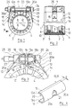
- the pipe coupling shown in Figures 1-3 has an annular housing 1, which is split in the direction of its longitudinal axis 1a.
- the housing 1 has a cylindrical casing 2 and inwardly curved side walls 3, 4.
- the housing gap 1b (FIG. 3) is bridged in a manner known per se by means of an insert plate 5.
- the housing 1 encloses an approximately C-shaped sealing sleeve 6 made of an elastomer, which is of a known type.
- This sealing sleeve 6 has a web 7 which bears against the casing 2 of the housing 1, from which project inwardly pointing and mutually extending sealing lips 8, 9 (FIG. 2). Laterally, the sealing sleeve 6 lies against a laminated anchoring ring 10, which is supported on the side walls 3, 4 of the housing 1.
- the housing 1 can be contracted by means of a clamping device 11 so as to reduce its diameter.
- This tensioning device 11 has two tensioning tabs 12, 13 arranged on the side of the housing gap 5, which are designed in the manner of loops.
- These tensioning straps 12, 13 are formed by a material section which is integral with the jacket 2 and bent back and which is welded to the jacket 2 at its end at the point designated by 14.
- Each clamping tab 12, 13 has an approximately radial, essentially flat wall section 12a or 13a. These two wall sections 12a, 13a lie opposite one another.
- Each clamping tab 12, 13 is provided with a through opening 15, which in the present embodiment is in the form of an elongated hole is formed (see Fig. 2).
- Each clamping bracket 12, 13 encloses a clamping member 16 or 17 with a U-shaped cross section, the legs 18, 19 of which are connected to one another via a curved part 20. In the end regions designated by c in FIG. 4, these legs 18 and 19 are essentially flat.
- the clamping members 16, 17 rest with the leg ends 18a, 19a on the flat wall sections 12a and 13a of the clamping members 12, 13, as can be clearly seen from FIGS. 1 and 3.
- a through hole 21 (FIG. 4) is formed in each clamping member 16, 17, through which the shaft 23 of a clamping screw 22 extends. This through hole 21 is at least in the circumferential direction of the corresponding clamping member 16, 17 larger than the outer diameter D (FIG. 3) of the screw shaft 23.
- the cylindrical screw head 24 in the present exemplary embodiment rests on the curved outer surface 20a of the clamping element 17, while a nut 25 screwed onto the screw shaft 23 is supported on the curved outer surface 20a of the opposite clamping element 16.
- the width a of the through opening 15 is preferably approximately equal to the width across flats b of the nut 25, so that the nut 25 is held in the opening 15 against rotation.
- the tightening screw 22 is tightened by means of a tool which can be inserted into a hexagon socket of the screw head 24, not shown in the figures.
- the sealing sleeve 6 has an excessive size compared to the outside diameter of the pipes to be coupled.
- the coupling is pushed onto the pipes in the pre-assembled state and pushed over a butt joint after laying the pipes.
- the housing 1 is contracted in the circumferential direction while reducing the diameter.
- the sealing sleeve 6, as is known in the case of such pipe couplings is pressed in a sealing manner against the outside of the pipes to be coupled.
- FIG. 1 the pipe coupling is shown in its open state, while Figure 3 shows the coupling housing 1 after assembly is complete.
- the clamping members 16, 17 are moved towards one another.
- the tensioning elements 16, 17 change their position with respect to the tensioning screw 22, as can easily be seen from a comparison of the two states shown in FIGS. 1 and 3.
- the relative movement that occurs between the clamping members 16, 17 and the screw shaft 23 is, as mentioned, not hindered because the screw shaft 23 is passed through the through holes 21 of the clamping members 16, 17 with play. Since both the screw head 24 and the nut 25 can roll on the curved outer surface 20a of the clamping members 16, 17, this adaptation movement between the screw shaft 23 and the supporting members 16, 17 is not impaired.
- the screw shaft 23 is essentially only subjected to tension and does not have to absorb any or only very slight bending forces. Accordingly, the screw shaft 23 can also be dimensioned less forcefully.
- the width of the housing gap 1b in the fully assembled state of the coupling can be kept smaller than in known pipe couplings of this type. This means that the insert plate 5 bridging the housing gap 1b can be dimensioned correspondingly weaker.
- the tensioning elements could also be designed as partial cylinders with a cylindrical surface serving as a support surface for the screw head 24 or the nut 25 and a flat surface which bears on the flat surfaces 12a, 13a of the clamping tabs 12, 13. It goes without saying that these partial cylinders would also have to be provided with a through opening for the screw shaft 23, which is larger than the outer diameter D of the screw shaft 23. However, such an embodiment has elements which are curved as U-shaped compared to the design of the clamping members 16, 17 shown the disadvantage that the force attack on the housing 1 is less favorable.
- the through hole for a given diameter D of the screw shaft 23 would have to be substantially larger than in the case of clamping members 16, 17 with a U-shaped cross section, by the same amount of relative mobility between screw shaft 23 and clamping members 16, 17 to enable.
- the width of the leg regions C By enlargement the width of the leg regions C, the bending stiffness of the U-shaped clamping members 16, 17 can be increased significantly.
Landscapes
- General Engineering & Computer Science (AREA)
- Engineering & Computer Science (AREA)
- Mechanical Engineering (AREA)
- Physics & Mathematics (AREA)
- Fluid Mechanics (AREA)
- Clamps And Clips (AREA)
- Joints Allowing Movement (AREA)
- Joints With Sleeves (AREA)
- Mechanical Coupling Of Light Guides (AREA)
- Optical Head (AREA)
- Semiconductor Lasers (AREA)
- Paper (AREA)
- Supports For Pipes And Cables (AREA)
- Mutual Connection Of Rods And Tubes (AREA)
- Preparation Of Compounds By Using Micro-Organisms (AREA)
- Meat, Egg Or Seafood Products (AREA)
- Non-Disconnectible Joints And Screw-Threaded Joints (AREA)
- Prostheses (AREA)
- Lasers (AREA)
- Flanged Joints, Insulating Joints, And Other Joints (AREA)
- Gasket Seals (AREA)
Abstract
Description
- Die vorliegende Erfindung betrifft eine Rohrkupplung gemäss Oberbegriff des Anspruches 1.
- Aus der DE-A-24 28 101 (bzw. der entsprechenden US-A-3,877,733) sowie der EP-A-0 447 955 (bzw. der entsprechenden US-A-5,137,305) sind Rohrkupplungen dieser Art bekannt, bei denen die Spannvorrichtung für das Gehäuse zwei zueinander parallele Gewindebolzen aufweist, die sich durch zwei zylindrische Spannbolzen hindurch erstrecken. Letztere verlaufen in Spannlaschen, die beidseits des durch eine Einlage überbrückten Gehäusespaltes am Gehäuse angebracht und mit Durchgangslöchern versehen sind, in deren Innengewinde die Gewindebolzen eingeschraubt sind. Die zylindrischen, mit einem Innensechskant versehenen Köpfe der Gewindebolzen kommen an einem Spannbolzen zur Auflage.
- Zum Zusammenziehen des Gehäuses, das ja das Andrücken der Dichtungsmanschette an die Rohrenden bewirkt, sind grosse Spannkräfte erforderlich. Zudem müssen bei der Montage der Rohrkupplung die Spannbolzen und damit auch die Spannlaschen einen verhältnismässig langen Weg aufeinander zu zurücklegen. Das hat zur Folge, dass über die Spannbolzen auf die in letztere eingeschraubten Gewindebolzen ganz erhebliche Biegekräfte übertragen werden, die zu einer Biegung der Gewindebolzen führen können. Beim Spannen treten dann nicht mehr nur in Umfangsrichtung des Gehäuses verlaufende Spannkräfte auf, sondern auch in radialer Richtung wirkende Kräfte, die ein einwandfreies Zusammenziehen des Gehäuses und damit ein gleichmässiges Anlegen der Dichtungsmanschette an die Rohrenden störend beeinflussen.
- In der DE-U-85 12 007 ist eine Rohrbruchschelle beschrieben, mit der eine die undichte Stelle einer Rohrleitung umfassende Dichtung dichtend an die Rohrleitung angelegt wird. Bei dieser bekannten Rohrbruchschelle sind am in Längsrichtung gespaltenen Gehäuse beidseits des Gehäusespaltes Laschen angebracht, durch die hindurch zylindrische Spannbolzen verlaufen. Letztere werden mit Spiel von Spannschrauben durchsetzt, die eine Mutter tragen, die sich am andern Spannbolzen abstützen. Der verhältnismässig grosse Gehäusespalt wird durch eine Einlage abgedeckt.
- Der vorliegenden Erfindung liegt nun die Aufgabe zugrunde, eine Rohrkupplung der eingangs genannten Art zu schaffen, bei der die Spannschraube möglichst frei von unerwünschten und störenden Biegekraft-Einwirkungen ist und bei der die auf das Gehäuse einwirkenden Spannkräfte im wesentlichen nur in Umfangsrichtung des Gehäuses wirken und möglichst nahe am Gehäuse eingeleitet werden können.
- Diese Aufgabe wird erfindungsgemäss durch die Merkmale des kennzeichnenden Teils des Anspruches 1 gelöst.
- Das Spiel zwischen dem Schaft der Spannschraube und den Spannorganen ermöglicht eine Relativbewegung zwischen letzteren und dem Schraubenschaft quer zur Spannrichtung, d.h. quer zur Schraubenlängsachse. Bei einer solchen Querbewegung, die beim Anziehen der Schraube und dem damit verursachten Zusammenbringen der Spannorgane auftritt, können sich sowohl der Schraubenkopf wie auch die Mutter auf der zugeordneten gewölbten Auflagefläche der im Querschnitt U-förmigen Spannorgane abwälzen. Diese besagte Querbewegung wird somit nicht durch die auf den Spannorganen aufliegenden Teile (Kopf und Mutter) der Spannschraube behindert. Die Spannschraube wird daher beim Spannen im wesentlichen nur auf Zug beansprucht. Das ermöglicht es, die Spannschraube und entsprechend auch die Spannorgane kleiner zu dimensionieren, wodurch Material und Gewicht eingespart werden können.
- Die beim Anziehen der Spannschraube im wesentlichen in Richtung deren Längsachse aufgebrachten Spannkräfte werden über die im Querschnitt U-förmigen Spannorgane so auf das Gehäuse übertragen, dass sie im wesentlichen in dessen Umfangsrichtung wirken und nahe am Umfang des Gehäuses eingeleitet werden. Letzteres wird besonders vorteilhaft bei der in den Ansprüchen 2 und 4 umschriebenen Ausführungsform erreicht.
- Im folgenden wird anhand der Zeichnung ein Ausführungbeispiel des Erfindungsgegenstandes näher erläutert. Es zeigt rein schematisch:
- Figur 1
- eine Rohrkupplung in Vorderansicht,
- Figur 2
- eine Ansicht der Kupplung gemäss Fig. 1 in Richtung des Pfeiles A, wobei die untere Kupplungshälfte im Schnitt dargestellt ist,
- Figur 3
- in einer der Fig. 1 entsprechenden Darstellung und in gegenüber letzterer vergrössertem Massstab den Bereich des Kupplungsgehäuses mit der Spanneinrichtung in verspanntem Zustand,
- Figur 4
- ein Spannorgan in perspektivischer Darstellung.
- Die in den Figuren 1-3 dargestellte Rohrkupplung weist ein ringförmiges Gehäuse 1 auf, das in Richtung seiner Längsachse 1a gespaltet ist. Das Gehäuse 1 besitzt einen zylindrischen Mantel 2 und einwärts gebogene Seitenwände 3, 4. Der Gehäusespalt 1b (Fig. 3) ist mittels eines Einlagebleches 5 in an sich bekannter Weise überbrückt.
- Das Gehäuse 1 umschliesst eine im Querschnitt etwa C-förmige Dichtungsmanschette 6 aus einem Elastomer, welche von bekannter Bauart ist. Diese Dichtungsmanschette 6 weist einen am Mantel 2 des Gehäuses 1 anliegenden Steg 7 auf, von dem nach innen weisende und sich gegeneinander erstreckende Dichtlippen 8, 9 (Fig. 2) abstehen. Seitlich liegt die Dichtungsmanschette 6 je an einem lamellierten Verankerungsring 10 an, der sich an den Seitenwänden 3, 4 des Gehäuses 1 abstützt.
- Das Gehäuse 1 lässt sich mittels einer Spanneinrichtung 11 zusammenziehen, um so dessen Durchmesser zu verkleinern. Diese Spanneinrichtung 11 weist zwei seitlich des Gehäusespaltes 5 angeordnete Spannlaschen 12, 13 auf, welche in der Art von Schlaufen ausgebildet sind. Diese Spannlaschen 12, 13 werden durch einen mit dem Mantel 2 einstückigen und zurückgebogenen Materialabschnitt gebildet, der an seinem Ende an der mit 14 bezeichneten Stelle mit dem Mantel 2 verschweisst ist. Jede Spannlasche 12, 13 weist einen etwa radial verlaufenden, im wesentlichen ebenen Wandabschnitt 12a bzw. 13a auf. Diese beiden Wandabschnitte 12a, 13a liegen sich gegenüber. Jede Spannlasche 12, 13 ist mit einer Durchgangsöffnung 15 versehen, die beim vorliegenden Ausführungsbeispiel in der Art eines Langloches ausgebildet ist (siehe Fig. 2). Jede Spannlasche 12, 13 umschliesst ein im Querschnitt U-förmiges Spannorgan 16 bzw. 17, dessen Schenkel 18, 19 über einen gewölbten Teil 20 miteinander verbunden sind. In den in Fig. 4 mit c bezeichneten Endbereichen sind diese Schenkel 18 und 19 im wesentlich eben. Die Spannorgane 16, 17 liegen mit den Schenkelenden 18a, 19a an den ebenen Wandabschnitten 12a bzw. 13a der Spannorgane 12, 13 auf, wie das aus den Figuren 1 und 3 deutlich hervorgeht. In jedem Spannorgan 16, 17 ist ein Durchgangsloch 21 (Fig. 4) ausgebildet, durch das sich der Schaft 23 einer Spannschraube 22 hindurcherstreckt. Dieses Durchgangsloch 21 ist dabei zumindest in Umfangsrichtung des entsprechenden Spannorganes 16,17 grösser als der Aussendurchmesser D (Fig. 3) des Schraubenschaftes 23. Dies bedeutet, dass der Schraubenschaft 23 diese Durchgangslöcher 21 mit radialem Spiel durchsetzt, so dass eine Relativbewegung zwischen Schraubenschaft 23 und den Spannorganen 16, 17 möglich ist. Der beim vorliegenden Ausführungsbeispiel zylindrische Schraubenkopf 24 liegt auf der gewölbten Aussenfläche 20a des Spannorganes 17 auf, während sich eine auf den Schraubenschaft 23 aufgeschraubte Mutter 25 auf der gewölbten Aussenfläche 20a des gegenüberliegenden Spannorganes 16 abstützt. Wie Fig. 2 zeigt, ist dabei vorzugsweise die Breite a der Durchgangsöffnung 15 etwa gleich der Schlüsselweite b der Mutter 25, so dass die Mutter 25 in der Oeffnung 15 gegen Verdrehung gehalten ist. Das Anziehen der Spannschraube 22 erfolgt mittels eines Werkzeuges, das in einen in den Figuren nicht dargestellten Innensechskant des Schraubenkopfes 24 eingeführt werden kann.
- Wie bekannt weist die Dichtungsmanschette 6 gegenüber dem Aussendurchmesser der zu kuppelnden Rohre ein Uebermass auf. Die Kupplung wird im vormontierten Zustand auf die Rohre aufgeschoben und nach dem Verlegen der Rohre über eine Stossfuge geschoben. Durch Drehen der Spannschraube 22 wird das Gehäuse 1 in Umfangsrichtung unter Verkleinerung des Durchmessers zusammengezogen. Dabei wird die Dichtungsmanschette 6, wie bei solchen Rohrkupplungen bekannt, dichtend an die Aussenseite der zu kuppelnden Rohre gepresst.
- In Fig. 1 ist die Rohrkupplung in ihrem geöffneten Zustand gezeigt, während die Figur 3 das Kupplungsgehäuse 1 nach beendigter Montage darstellt. Während des Zusammenziehens des Gehäuses 1 werden die Spannorgane 16, 17 aufeinander zu bewegt. Bei dieser Bewegung ändern die Spannorgane 16, 17 ihre Lage bezüglich der Spannschraube 22, wie sich das ohne weiteres aus einem Vergleich der beiden in den Figuren 1 und 3 dargestellten Zustände erkennen lässt. Die dabei auftretende Relativbewegung zwischen den Spannorganen 16, 17 und dem Schraubenschaft 23 wird, wie erwähnt, deswegen nicht behindert, weil der Schraubenschaft 23 mit Spiel durch die Durchgangslöcher 21 der Spannorgane 16, 17 hindurchgeführt ist. Da sich dabei sowohl der Schraubenkopf 24 wie auch die Mutter 25 auf der gekrümmten Aussenfläche 20a der Spannorgane 16, 17 abwälzen können, wird diese Anpassbewegung zwischen Schraubenschaft 23 und Stützorganen 16, 17 nicht beeinträchtigt. Der Schraubenschaft 23 wird im wesentlichen nur auf Zug beansprucht und muss keine oder nur sehr geringe Biegekräfte aufnehmen. Dementsprechend kann der Schraubenschaft 23 auch weniger kräftig bemessen werden.
- Die von Schraubenkopf 24 und Mutter 25 auf die zugeordneten Spannorgane 16, 17 ausgeübten Kräfte werden von letzteren auf die ebenen Wandabschnitte 12a, 13a der Spannlaschen 12, 13, die, wie erwähnt etwa radial verlaufen, übertragen. Dadurch wird erreicht, dass die Spannkräfte im wesentlichen in Umfangsrichtung des Gehäuses 1 wirken. Die Einleitung der Spannkräfte kann nahe am Umfang des Gehäuses 1 erfolgen.
- Die Breite des Gehäusespaltes 1b im fertigmontierten Zustand der Kupplung kann kleiner gehalten werden als bei bekannten Rohrkupplungen dieser Art. Dies bedeutet, dass das den Gehäusespalt 1b überbrückende Einlageblech 5 entsprechend schwächer dimensioniert werden kann.
- Die Spannorgane könnten auch als Teilzylinder mit einer als Stützfläche für den Schraubenkopf 24 bzw. die Mutter 25 dienenden zylindrischen Fläche und einer ebenen Fläche ausgebildet sein, die an den ebenen Flächen 12a, 13a der Spannlaschen 12, 13 anliegt. Es versteht sich, dass auch diese Teilzylinder mit einer Durchgangsöffnung für den Schraubenschaft 23 versehen sein müssten, welche grösser ist als der Aussendurchmesser D des Schraubenschaftes 23. Eine solche Ausführungsform hat jedoch gegenüber der gezeigten Ausbildung der Spannorgane 16, 17 als U-förmig gebogene Elemente den Nachteil, dass der Kraftangriff am Gehäuse 1 weniger günstig ist. Zudem müsste bei als Teil-, vorzugsweise Halbzylindern, ausgebildeten Spannorganen, das Durchgangsloch bei gegebenem Durchmesser D des Schraubenschaftes 23 wesentlich grösser sein als bei im Querschnitt U-förmigen Spannorganen 16, 17, um dasselbe Mass von Relativbeweglichkeit zwischen Schraubenschaft 23 und Spannorganen 16, 17 zu ermöglichen. Durch Vergrösserung der Breite der Schenkelbereiche C kann die Biegesteifigkeit der U-förmigen Spannorgane 16, 17 wesentlich erhöht werden.
Claims (6)
- Rohrkupplung mit einer vor der Montage gegenüber dem Aussendurchmesser der zu kuppelnden Rohre Uebermass aufweisenden Elastomer-Dichtungsmanschette (6), die von einem ringförmigen und in Richtung der Längsachse (1a) gespaltenen Gehäuse (1) umschlossen ist, das zum Anlegen der Dichtungsmanschette (6) an die Rohre mittels einer Spanneinrichtung (11) in Umfangsrichtung, zusammenziehbar ist, die wenigstens eine im wesentlichen tangential zum Gehäuse (1) verlaufende Spannschraube (22) aufweist, die sich durch zwei je auf einer Seite des Gehäusespaltes (1b) am Gehäuse (1) angreifende Spannorgane (16, 17) hindurch erstreckt und mit ihrem Kopf (24) an einer gewölbten Aussenfläche (20a) des einen Spannorganes (17) anliegt, dadurch gekennzeichnet, dass der Schaft (23) der Spannschraube (22) die Spannorgane (16, 17), die im Querschnitt im wesentlichen U-förmig ausgebildet sind, mit Spiel durchsetzt und eine Mutter (25) trägt, die sich an einer ebenfalls gewölbten Aussenfläche (20a) des anderen Spannorganes (16) abstützt.
- Rohrkupplung nach Anspruch 1, dadurch gekennzeichnet, dass am Gehäuse (1) beidseits des Gehäusespaltes (5) Spannlaschen (12, 13) angebracht sind, an denen die Spannorgane (16, 17) mit ihren Schenkelenden (18a, 19a) angreifen und die eine Durchgangsöffnung (15) für den Schaft (23) der Spannschraube (22) aufweisen.
- Rohrkupplung nach Anspruch 1 oder 2, dadurch gekennzeichnet, dass die Spannorgane (16, 17) wenigstens ein Durchgangsloch (21) aufweisen, dessen Innenabmessung in Umfangsrichtung der Spannorgane (16, 17) grösser ist als der Aussendurchmesser (D) des Spannschraubenschaftes (23).
- Rohrkupplung nach Anspruch 2 dadurch gekennzeichnet, dass die als Schlaufen ausgebildeten Spannlaschen (12, 13) einen dem Gehäusespalt (1b) zugekehrten Wandabschnitt (12a, 13a) aufweisen, der im wesentlichen eben ist, sich vorzugsweise etwa in radialer Richtung erstreckt und als Auflage für das jeweils zugeordnete Spannorgan (16, 17) dient.
- Rohrkupplung nach Anspruch 2, dadurch gekennzeichnet, dass die Breite (a) der Durchgangsöffnung (15) wenigstens einer Spannlasche (12) etwa gleich der Schlüsselweite (b) der Mutter (25) der Spannschraube (22) ist.
- Rohrkupplung nach Anspruch 1, dadurch gekennzeichnet, dass die Dichtmanschette (6) im Querschnitt etwa C-förmig ausgebildet ist und sich gegeneinander erstreckende Dichtlippen (8, 9) aufweist, die dichtend an jeweils einer der Rohrenden zur Anlage bringbar sind.
Applications Claiming Priority (2)
| Application Number | Priority Date | Filing Date | Title |
|---|---|---|---|
| CH1592 | 1992-01-07 | ||
| CH15/92 | 1992-01-07 |
Publications (2)
| Publication Number | Publication Date |
|---|---|
| EP0550813A1 true EP0550813A1 (de) | 1993-07-14 |
| EP0550813B1 EP0550813B1 (de) | 1997-02-12 |
Family
ID=4177472
Family Applications (1)
| Application Number | Title | Priority Date | Filing Date |
|---|---|---|---|
| EP92119104A Expired - Lifetime EP0550813B1 (de) | 1992-01-07 | 1992-11-07 | Rohrkupplung |
Country Status (17)
| Country | Link |
|---|---|
| US (1) | US5280970A (de) |
| EP (1) | EP0550813B1 (de) |
| JP (1) | JPH0811991B2 (de) |
| KR (1) | KR960006176B1 (de) |
| CN (1) | CN1030102C (de) |
| AT (1) | ATE148935T1 (de) |
| AU (1) | AU658464B2 (de) |
| BR (1) | BR9300007A (de) |
| CA (1) | CA2083902C (de) |
| DE (1) | DE59208039D1 (de) |
| DK (1) | DK0550813T3 (de) |
| ES (1) | ES2097264T3 (de) |
| FI (1) | FI102207B (de) |
| MX (1) | MX9207474A (de) |
| NO (1) | NO307148B1 (de) |
| RU (1) | RU2075001C1 (de) |
| ZA (1) | ZA929223B (de) |
Cited By (4)
| Publication number | Priority date | Publication date | Assignee | Title |
|---|---|---|---|---|
| WO1995011402A1 (en) * | 1993-10-22 | 1995-04-27 | Taylor Kerr (Couplings) Limited | Pipe coupling |
| DE19542463A1 (de) * | 1995-11-15 | 1997-05-28 | Mero Gmbh & Co Kg | Rohrkupplung |
| EP0989349A1 (de) | 1998-09-21 | 2000-03-29 | Straub Federnfabrik AG | Rohrkupplung |
| WO2012162456A1 (en) * | 2011-05-26 | 2012-11-29 | Eliezer Krausz Industries Development Ltd. | Clamp assembly with resilient band having notches |
Families Citing this family (47)
| Publication number | Priority date | Publication date | Assignee | Title |
|---|---|---|---|---|
| GB9611410D0 (en) | 1996-05-31 | 1996-08-07 | Taylor Kerr Couplings Ltd | Pipe coupling |
| RU2137012C1 (ru) * | 1998-06-11 | 1999-09-10 | Ларин Вячеслав Иванович | Трубная муфта |
| DE19901663C2 (de) * | 1999-01-18 | 2001-02-22 | Rasmussen Gmbh | Rohrkupplung |
| DE20108026U1 (de) * | 2001-05-13 | 2001-08-09 | Landwehr, Wilhelm, 26388 Wilhelmshaven | Klemmspaltmutter |
| ES2233811T3 (es) * | 2001-05-13 | 2005-06-16 | Wilhelm Landwehr | Tuerca de apriete con separacion. |
| US7004512B2 (en) * | 2002-06-19 | 2006-02-28 | Voss Industries, Inc. | Indented apex V-retainer coupling with cushion |
| RU2256841C2 (ru) * | 2003-08-28 | 2005-07-20 | Общество с ограниченной ответственностью "Севергазпром" | Трубная муфта и способ ее изготовления |
| US20050082831A1 (en) * | 2003-10-15 | 2005-04-21 | Borland Robin N. | Conduit coupling |
| RU2262030C1 (ru) * | 2004-03-30 | 2005-10-10 | Тверской государственный технический университет | Быстроразборная соединительная муфта для трубопроводов |
| US7712796B2 (en) * | 2004-05-14 | 2010-05-11 | Victaulic Company | Deformable mechanical pipe coupling |
| US7086131B2 (en) * | 2004-05-14 | 2006-08-08 | Victaulic Company | Deformable mechanical pipe coupling |
| US7422246B2 (en) * | 2004-08-26 | 2008-09-09 | Straub Tadco Inc. | Remote pipe coupling system |
| FR2884582B1 (fr) * | 2005-04-13 | 2010-01-08 | Caillau Ets | Dispositif pour l'accouplement etanche de deux tubes lisses |
| FR2884563B1 (fr) * | 2005-04-13 | 2011-03-18 | Caillau Ets | Dispositif de serrage a oreilles de serrage renforcees |
| IL174110A0 (en) * | 2006-03-05 | 2006-08-01 | Krausz Metal Ind Ltd | Pipes coupling with integrated grip |
| US7726703B2 (en) * | 2006-06-07 | 2010-06-01 | Victaulic Company | Deformable pipe coupling having multiple radii of curvature |
| JP2008045598A (ja) * | 2006-08-11 | 2008-02-28 | Toa Kokyu Pipe Fitting & Valve Mfg Co Ltd | 管継手 |
| DE102007010342B4 (de) * | 2007-03-03 | 2019-10-02 | Man Energy Solutions Se | Rohrkupplung |
| RU2330207C1 (ru) * | 2007-03-26 | 2008-07-27 | Государственное образовательное учреждение высшего профессионального образования Саратовский государственный технический университет | Трубная муфта |
| FR2915537B1 (fr) * | 2007-04-24 | 2012-07-20 | Caillau Ets | Dispositif de serrage |
| US8282136B2 (en) | 2008-06-30 | 2012-10-09 | Mueller International, Llc | Slip on groove coupling with multiple sealing gasket |
| JP5175007B2 (ja) * | 2008-07-01 | 2013-04-03 | 株式会社リケン | ハウジング形管継手 |
| FR2933756B1 (fr) * | 2008-07-10 | 2013-06-14 | Caillau Ets | Dispositif de serrage comprenant un collier |
| DK200900718A (en) | 2009-06-08 | 2010-12-09 | Coloplast As | Anatomical augmentation device |
| KR101040685B1 (ko) * | 2011-03-07 | 2011-06-13 | 벽진산업 주식회사 | 관 고정용 환봉 연결구 |
| USD696751S1 (en) | 2011-10-27 | 2013-12-31 | Mueller International, Llc | Slip-on gasket |
| USD680630S1 (en) | 2011-11-21 | 2013-04-23 | Mueller International, Llc | Slip-on coupling assembly |
| US9395024B2 (en) | 2011-11-21 | 2016-07-19 | Victaulic Company | Coupling having gasket pocket of varying depth |
| USD680629S1 (en) | 2011-11-21 | 2013-04-23 | Mueller International, Llc | Slip-on coupling segment |
| US9039046B2 (en) | 2012-01-20 | 2015-05-26 | Mueller International, Llc | Coupling with tongue and groove |
| US9194516B2 (en) | 2012-01-20 | 2015-11-24 | Mueller International, Llc | Slip-on coupling |
| US9500307B2 (en) | 2012-01-20 | 2016-11-22 | Mueller International, Llc | Slip-on coupling gasket |
| US9534715B2 (en) | 2012-01-20 | 2017-01-03 | Mueller International, Llc | Coupling gasket with multiple sealing surfaces |
| US8820795B2 (en) | 2012-02-02 | 2014-09-02 | Victaulic Company | Fitting for joining pipe elements |
| US9182058B2 (en) | 2012-02-08 | 2015-11-10 | Victaulic Company | Fitting having receptacle of varying depth |
| US8894100B2 (en) | 2012-03-16 | 2014-11-25 | Romac Industries, Inc. | Fitting with draw mechanism |
| US9168585B2 (en) | 2012-11-02 | 2015-10-27 | Mueller International, Llc | Coupling with extending parting line |
| US10578234B2 (en) | 2013-05-02 | 2020-03-03 | Victaulic Company | Coupling having arcuate stiffness ribs |
| CN105473923B (zh) | 2013-07-17 | 2018-01-19 | 维克托里克公司 | 具有拱形刚度肋的配件 |
| DK3397884T3 (da) | 2015-12-28 | 2020-08-03 | Victaulic Co Of America | Adapterkobling |
| US10859190B2 (en) | 2016-05-16 | 2020-12-08 | Victaulic Company | Sprung coupling |
| US10533688B2 (en) | 2016-05-16 | 2020-01-14 | Victaulic Company | Coupling having tabbed retainer |
| US10605394B2 (en) | 2016-05-16 | 2020-03-31 | Victaulic Company | Fitting having tabbed retainer and observation apertures |
| RU182503U1 (ru) * | 2017-12-05 | 2018-08-21 | Вячеслав Алексеевич Медведев | Устройство для ремонта трубопровода |
| CN108397621B (zh) * | 2018-03-15 | 2019-08-06 | 安徽江淮汽车集团股份有限公司 | 一种弹性卡箍总成 |
| US11781683B2 (en) | 2019-11-15 | 2023-10-10 | Victaulic Company | Shrouded coupling |
| RU209374U1 (ru) * | 2021-07-13 | 2022-03-15 | Общество с ограниченной ответственностью "МУФТЫ НСК" | Трубная муфта |
Citations (5)
| Publication number | Priority date | Publication date | Assignee | Title |
|---|---|---|---|---|
| GB573695A (en) * | 1943-08-17 | 1945-12-03 | Robert Cuthbert Scott Jamie | Improvements in or relating to metal hose clips |
| GB573698A (en) * | 1943-08-17 | 1945-12-03 | Robert Cuthbert Scott Jamie | Improvements in or relating to screw mechanism for tightening metal band clips |
| GB573696A (en) * | 1943-08-17 | 1945-12-03 | Robert Cuthbert Scott Jamie | Improvements in or relating to multiple metal hose clips |
| EP0079457A1 (de) * | 1981-11-05 | 1983-05-25 | Immanuel Straub | Rohrkupplung sowie Verwendung derselben |
| DE8512007U1 (de) * | 1985-04-23 | 1985-06-05 | Huckenbeck, Friedrich Wilhelm, 5828 Ennepetal | Rohrbruchschelle |
Family Cites Families (11)
| Publication number | Priority date | Publication date | Assignee | Title |
|---|---|---|---|---|
| US2073294A (en) * | 1935-01-17 | 1937-03-09 | Caillau Marcel Urbain | Hose clamp |
| US3199835A (en) * | 1961-08-31 | 1965-08-10 | Duriron Co | Sleeve lined plug valves |
| US3507314A (en) * | 1968-10-18 | 1970-04-21 | Aeroquip Corp | Self-locking barrel nut |
| US3877733A (en) * | 1973-06-14 | 1975-04-15 | Immanuel Straub | Pipe coupling |
| US3861723A (en) * | 1973-08-28 | 1975-01-21 | Us Air Force | V-band coupling |
| DE3570114D1 (en) * | 1984-09-27 | 1989-06-15 | Mage Ag | Tension collar with tension screw |
| CH666949A5 (de) * | 1985-08-09 | 1988-08-31 | Immanuel Straub | Rohrkupplung. |
| FR2613786B1 (fr) * | 1987-04-09 | 1990-11-30 | Pont A Mousson | Collier a vis de serrage pivotante |
| JPS6454600A (en) * | 1987-08-25 | 1989-03-02 | Nec Corp | Transmitting equipment for guard information |
| JP2754016B2 (ja) * | 1988-08-11 | 1998-05-20 | カヤバ工業株式会社 | パワーステアリング装置 |
| CH681318A5 (de) * | 1990-03-20 | 1993-02-26 | Straub Federnfabrik |
-
1992
- 1992-11-07 DK DK92119104.5T patent/DK0550813T3/da active
- 1992-11-07 AT AT92119104T patent/ATE148935T1/de not_active IP Right Cessation
- 1992-11-07 EP EP92119104A patent/EP0550813B1/de not_active Expired - Lifetime
- 1992-11-07 DE DE59208039T patent/DE59208039D1/de not_active Expired - Fee Related
- 1992-11-07 ES ES92119104T patent/ES2097264T3/es not_active Expired - Lifetime
- 1992-11-27 CA CA002083902A patent/CA2083902C/en not_active Expired - Fee Related
- 1992-11-27 ZA ZA929223A patent/ZA929223B/xx unknown
- 1992-12-07 AU AU29939/92A patent/AU658464B2/en not_active Ceased
- 1992-12-09 JP JP4352028A patent/JPH0811991B2/ja not_active Expired - Fee Related
- 1992-12-10 US US07/988,721 patent/US5280970A/en not_active Expired - Fee Related
- 1992-12-21 MX MX9207474A patent/MX9207474A/es not_active IP Right Cessation
- 1992-12-24 RU RU9292016266A patent/RU2075001C1/ru active
- 1992-12-30 KR KR1019920026688A patent/KR960006176B1/ko not_active Expired - Fee Related
-
1993
- 1993-01-05 FI FI930037A patent/FI102207B/fi active
- 1993-01-05 BR BR9300007A patent/BR9300007A/pt not_active IP Right Cessation
- 1993-01-06 NO NO930030A patent/NO307148B1/no unknown
- 1993-01-07 CN CN93100162A patent/CN1030102C/zh not_active Expired - Lifetime
Patent Citations (5)
| Publication number | Priority date | Publication date | Assignee | Title |
|---|---|---|---|---|
| GB573695A (en) * | 1943-08-17 | 1945-12-03 | Robert Cuthbert Scott Jamie | Improvements in or relating to metal hose clips |
| GB573698A (en) * | 1943-08-17 | 1945-12-03 | Robert Cuthbert Scott Jamie | Improvements in or relating to screw mechanism for tightening metal band clips |
| GB573696A (en) * | 1943-08-17 | 1945-12-03 | Robert Cuthbert Scott Jamie | Improvements in or relating to multiple metal hose clips |
| EP0079457A1 (de) * | 1981-11-05 | 1983-05-25 | Immanuel Straub | Rohrkupplung sowie Verwendung derselben |
| DE8512007U1 (de) * | 1985-04-23 | 1985-06-05 | Huckenbeck, Friedrich Wilhelm, 5828 Ennepetal | Rohrbruchschelle |
Cited By (7)
| Publication number | Priority date | Publication date | Assignee | Title |
|---|---|---|---|---|
| WO1995011402A1 (en) * | 1993-10-22 | 1995-04-27 | Taylor Kerr (Couplings) Limited | Pipe coupling |
| DE19542463A1 (de) * | 1995-11-15 | 1997-05-28 | Mero Gmbh & Co Kg | Rohrkupplung |
| DE19542463B4 (de) * | 1995-11-15 | 2004-05-27 | J. Van Walraven B.V. | Rohrkupplung |
| EP0989349A1 (de) | 1998-09-21 | 2000-03-29 | Straub Federnfabrik AG | Rohrkupplung |
| WO2000017558A1 (de) | 1998-09-21 | 2000-03-30 | Wantoch, Manfred | Rohrkupplung oder rohrschelle |
| WO2012162456A1 (en) * | 2011-05-26 | 2012-11-29 | Eliezer Krausz Industries Development Ltd. | Clamp assembly with resilient band having notches |
| US9249908B2 (en) | 2011-05-26 | 2016-02-02 | Krausz Industries Development Ltd. | Clamp assembly with resilient band having notches |
Also Published As
| Publication number | Publication date |
|---|---|
| CN1074285A (zh) | 1993-07-14 |
| KR960006176B1 (ko) | 1996-05-09 |
| FI930037A0 (fi) | 1993-01-05 |
| KR930016705A (ko) | 1993-08-26 |
| ES2097264T3 (es) | 1997-04-01 |
| MX9207474A (es) | 1993-11-01 |
| NO307148B1 (no) | 2000-02-14 |
| NO930030L (no) | 1993-07-08 |
| FI102207B1 (fi) | 1998-10-30 |
| DE59208039D1 (de) | 1997-03-27 |
| ZA929223B (en) | 1993-05-26 |
| ATE148935T1 (de) | 1997-02-15 |
| DK0550813T3 (da) | 1997-03-10 |
| AU658464B2 (en) | 1995-04-13 |
| JPH0811991B2 (ja) | 1996-02-07 |
| FI102207B (fi) | 1998-10-30 |
| AU2993992A (en) | 1993-07-08 |
| JPH05248574A (ja) | 1993-09-24 |
| BR9300007A (pt) | 1993-07-13 |
| US5280970A (en) | 1994-01-25 |
| NO930030D0 (no) | 1993-01-06 |
| FI930037L (fi) | 1993-07-08 |
| RU2075001C1 (ru) | 1997-03-10 |
| EP0550813B1 (de) | 1997-02-12 |
| CA2083902C (en) | 1996-03-19 |
| CN1030102C (zh) | 1995-10-18 |
| CA2083902A1 (en) | 1993-07-08 |
Similar Documents
| Publication | Publication Date | Title |
|---|---|---|
| EP0550813B1 (de) | Rohrkupplung | |
| DE3781891T2 (de) | Bandschelle mit uebergrossen spannschraubenloechern. | |
| DE69411935T2 (de) | Schlauchschelle | |
| DE69614141T2 (de) | Anschlussvorrichtung für rohre | |
| DE2731464A1 (de) | Rohrkupplung | |
| DE2802937A1 (de) | Anordnung zur schubsicherung fuer eine muffenrohrverbindung | |
| DE69724392T2 (de) | Verfahren zum Verbinden von Rohren | |
| EP0079457A1 (de) | Rohrkupplung sowie Verwendung derselben | |
| DE2541980A1 (de) | Rohrschelle | |
| DE2112591A1 (de) | Aufweitbare Befestigungsvorrichtung | |
| DE1625917A1 (de) | Schlauchverbindung | |
| CH622597A5 (en) | Socket connection for pipes or pipe fittings | |
| EP0846908A1 (de) | Verbindung zwischen einem Rohr und einem Formteil | |
| EP0889271B1 (de) | Rohrverbindung zweier sich überlappender Rohre | |
| WO2016120223A1 (de) | Profilschelle | |
| DE60107110T2 (de) | Sicherheitskupplung | |
| DE2501889C3 (de) | RohrdichtscheUe | |
| DE3926432A1 (de) | Rohrkupplung | |
| DE4103701C1 (de) | ||
| DE10217750B4 (de) | Schelle mit geschlitzten Bandschlaufen zum Einhängen eines Verschlusses | |
| DE19638029A1 (de) | Rohrverbindung mit Spannring | |
| DE3908060A1 (de) | Rohrverbindung | |
| DE19939562C1 (de) | Spannbare Schelle | |
| EP0184783B1 (de) | Vorrichtung zum abgedichteten Verbinden der glattzylindrischen Enden zweier Rohre | |
| DE3301229A1 (de) | Breitbandschelle zum abgedichteten verbinden von glattzylindrischen rohrenden, insbesondere von abwasserrohren mittels eines dichtungselements |
Legal Events
| Date | Code | Title | Description |
|---|---|---|---|
| PUAI | Public reference made under article 153(3) epc to a published international application that has entered the european phase |
Free format text: ORIGINAL CODE: 0009012 |
|
| AK | Designated contracting states |
Kind code of ref document: A1 Designated state(s): AT BE CH DE DK ES FR GB IT LI NL SE |
|
| 17P | Request for examination filed |
Effective date: 19930623 |
|
| 17Q | First examination report despatched |
Effective date: 19950123 |
|
| GRAG | Despatch of communication of intention to grant |
Free format text: ORIGINAL CODE: EPIDOS AGRA |
|
| GRAH | Despatch of communication of intention to grant a patent |
Free format text: ORIGINAL CODE: EPIDOS IGRA |
|
| GRAH | Despatch of communication of intention to grant a patent |
Free format text: ORIGINAL CODE: EPIDOS IGRA |
|
| GRAA | (expected) grant |
Free format text: ORIGINAL CODE: 0009210 |
|
| ITF | It: translation for a ep patent filed | ||
| AK | Designated contracting states |
Kind code of ref document: B1 Designated state(s): AT BE CH DE DK ES FR GB IT LI NL SE |
|
| REF | Corresponds to: |
Ref document number: 148935 Country of ref document: AT Date of ref document: 19970215 Kind code of ref document: T |
|
| REG | Reference to a national code |
Ref country code: CH Ref legal event code: EP Ref country code: CH Ref legal event code: NV Representative=s name: PATENTANWAELTE SCHAAD, BALASS, MENZL & PARTNER AG |
|
| ET | Fr: translation filed | ||
| REG | Reference to a national code |
Ref country code: DK Ref legal event code: T3 |
|
| GBT | Gb: translation of ep patent filed (gb section 77(6)(a)/1977) |
Effective date: 19970214 |
|
| REF | Corresponds to: |
Ref document number: 59208039 Country of ref document: DE Date of ref document: 19970327 |
|
| REG | Reference to a national code |
Ref country code: ES Ref legal event code: FG2A Ref document number: 2097264 Country of ref document: ES Kind code of ref document: T3 |
|
| PLBE | No opposition filed within time limit |
Free format text: ORIGINAL CODE: 0009261 |
|
| STAA | Information on the status of an ep patent application or granted ep patent |
Free format text: STATUS: NO OPPOSITION FILED WITHIN TIME LIMIT |
|
| 26N | No opposition filed | ||
| PGFP | Annual fee paid to national office [announced via postgrant information from national office to epo] |
Ref country code: ES Payment date: 20001114 Year of fee payment: 9 |
|
| PGFP | Annual fee paid to national office [announced via postgrant information from national office to epo] |
Ref country code: FR Payment date: 20001121 Year of fee payment: 9 |
|
| PGFP | Annual fee paid to national office [announced via postgrant information from national office to epo] |
Ref country code: AT Payment date: 20001122 Year of fee payment: 9 Ref country code: DK Payment date: 20001122 Year of fee payment: 9 |
|
| PGFP | Annual fee paid to national office [announced via postgrant information from national office to epo] |
Ref country code: BE Payment date: 20001123 Year of fee payment: 9 Ref country code: NL Payment date: 20001123 Year of fee payment: 9 |
|
| PGFP | Annual fee paid to national office [announced via postgrant information from national office to epo] |
Ref country code: SE Payment date: 20001124 Year of fee payment: 9 |
|
| PGFP | Annual fee paid to national office [announced via postgrant information from national office to epo] |
Ref country code: CH Payment date: 20001128 Year of fee payment: 9 |
|
| PG25 | Lapsed in a contracting state [announced via postgrant information from national office to epo] |
Ref country code: DK Free format text: LAPSE BECAUSE OF NON-PAYMENT OF DUE FEES Effective date: 20011107 Ref country code: AT Free format text: LAPSE BECAUSE OF NON-PAYMENT OF DUE FEES Effective date: 20011107 |
|
| PG25 | Lapsed in a contracting state [announced via postgrant information from national office to epo] |
Ref country code: SE Free format text: LAPSE BECAUSE OF NON-PAYMENT OF DUE FEES Effective date: 20011108 Ref country code: ES Free format text: LAPSE BECAUSE OF NON-PAYMENT OF DUE FEES Effective date: 20011108 |
|
| PG25 | Lapsed in a contracting state [announced via postgrant information from national office to epo] |
Ref country code: LI Free format text: LAPSE BECAUSE OF NON-PAYMENT OF DUE FEES Effective date: 20011130 Ref country code: BE Free format text: LAPSE BECAUSE OF NON-PAYMENT OF DUE FEES Effective date: 20011130 Ref country code: CH Free format text: LAPSE BECAUSE OF NON-PAYMENT OF DUE FEES Effective date: 20011130 |
|
| REG | Reference to a national code |
Ref country code: GB Ref legal event code: IF02 |
|
| BERE | Be: lapsed |
Owner name: STRAUB FEDERNFABRIK A.G. Effective date: 20011130 |
|
| PG25 | Lapsed in a contracting state [announced via postgrant information from national office to epo] |
Ref country code: NL Free format text: LAPSE BECAUSE OF NON-PAYMENT OF DUE FEES Effective date: 20020601 |
|
| EUG | Se: european patent has lapsed |
Ref document number: 92119104.5 |
|
| REG | Reference to a national code |
Ref country code: CH Ref legal event code: PL |
|
| REG | Reference to a national code |
Ref country code: DK Ref legal event code: EBP |
|
| PG25 | Lapsed in a contracting state [announced via postgrant information from national office to epo] |
Ref country code: FR Free format text: LAPSE BECAUSE OF NON-PAYMENT OF DUE FEES Effective date: 20020730 |
|
| NLV4 | Nl: lapsed or anulled due to non-payment of the annual fee |
Effective date: 20020601 |
|
| REG | Reference to a national code |
Ref country code: FR Ref legal event code: ST |
|
| REG | Reference to a national code |
Ref country code: FR Ref legal event code: ST |
|
| REG | Reference to a national code |
Ref country code: ES Ref legal event code: FD2A Effective date: 20021213 |
|
| PG25 | Lapsed in a contracting state [announced via postgrant information from national office to epo] |
Ref country code: IT Free format text: LAPSE BECAUSE OF NON-PAYMENT OF DUE FEES;WARNING: LAPSES OF ITALIAN PATENTS WITH EFFECTIVE DATE BEFORE 2007 MAY HAVE OCCURRED AT ANY TIME BEFORE 2007. THE CORRECT EFFECTIVE DATE MAY BE DIFFERENT FROM THE ONE RECORDED. Effective date: 20051107 |
|
| PGFP | Annual fee paid to national office [announced via postgrant information from national office to epo] |
Ref country code: DE Payment date: 20081210 Year of fee payment: 17 |
|
| PGFP | Annual fee paid to national office [announced via postgrant information from national office to epo] |
Ref country code: GB Payment date: 20081119 Year of fee payment: 17 |
|
| GBPC | Gb: european patent ceased through non-payment of renewal fee |
Effective date: 20091107 |
|
| PG25 | Lapsed in a contracting state [announced via postgrant information from national office to epo] |
Ref country code: DE Free format text: LAPSE BECAUSE OF NON-PAYMENT OF DUE FEES Effective date: 20100601 |
|
| PG25 | Lapsed in a contracting state [announced via postgrant information from national office to epo] |
Ref country code: GB Free format text: LAPSE BECAUSE OF NON-PAYMENT OF DUE FEES Effective date: 20091107 |