EP0550841B1 - Fassadenkonstruktion - Google Patents
Fassadenkonstruktion Download PDFInfo
- Publication number
- EP0550841B1 EP0550841B1 EP92120993A EP92120993A EP0550841B1 EP 0550841 B1 EP0550841 B1 EP 0550841B1 EP 92120993 A EP92120993 A EP 92120993A EP 92120993 A EP92120993 A EP 92120993A EP 0550841 B1 EP0550841 B1 EP 0550841B1
- Authority
- EP
- European Patent Office
- Prior art keywords
- structure according
- facade
- facade structure
- cover
- main support
- Prior art date
- Legal status (The legal status is an assumption and is not a legal conclusion. Google has not performed a legal analysis and makes no representation as to the accuracy of the status listed.)
- Expired - Lifetime
Links
- 238000009413 insulation Methods 0.000 claims abstract description 55
- 229920003023 plastic Polymers 0.000 claims description 17
- 239000004033 plastic Substances 0.000 claims description 17
- 238000007789 sealing Methods 0.000 claims description 16
- 238000000926 separation method Methods 0.000 claims description 16
- 125000006850 spacer group Chemical group 0.000 claims description 10
- 239000000463 material Substances 0.000 claims description 3
- 238000004040 coloring Methods 0.000 claims description 2
- 239000002470 thermal conductor Substances 0.000 claims 9
- 229910000831 Steel Inorganic materials 0.000 claims 2
- 239000010959 steel Substances 0.000 claims 2
- 238000005192 partition Methods 0.000 abstract 2
- 238000010276 construction Methods 0.000 description 32
- 230000003068 static effect Effects 0.000 description 7
- 230000000694 effects Effects 0.000 description 6
- 229910052782 aluminium Inorganic materials 0.000 description 4
- XAGFODPZIPBFFR-UHFFFAOYSA-N aluminium Chemical compound [Al] XAGFODPZIPBFFR-UHFFFAOYSA-N 0.000 description 4
- 229910001220 stainless steel Inorganic materials 0.000 description 4
- 239000010935 stainless steel Substances 0.000 description 4
- 239000004020 conductor Substances 0.000 description 3
- 230000000717 retained effect Effects 0.000 description 3
- 239000000853 adhesive Substances 0.000 description 2
- 230000001070 adhesive effect Effects 0.000 description 2
- 230000004888 barrier function Effects 0.000 description 2
- 229910052751 metal Inorganic materials 0.000 description 2
- 239000002184 metal Substances 0.000 description 2
- 230000015572 biosynthetic process Effects 0.000 description 1
- 238000005253 cladding Methods 0.000 description 1
- 238000009833 condensation Methods 0.000 description 1
- 230000005494 condensation Effects 0.000 description 1
- 238000000605 extraction Methods 0.000 description 1
- 239000003517 fume Substances 0.000 description 1
- 239000011521 glass Substances 0.000 description 1
- 238000004519 manufacturing process Methods 0.000 description 1
- 238000000034 method Methods 0.000 description 1
- XLYOFNOQVPJJNP-UHFFFAOYSA-N water Substances O XLYOFNOQVPJJNP-UHFFFAOYSA-N 0.000 description 1
Images


Classifications
-
- E—FIXED CONSTRUCTIONS
- E04—BUILDING
- E04B—GENERAL BUILDING CONSTRUCTIONS; WALLS, e.g. PARTITIONS; ROOFS; FLOORS; CEILINGS; INSULATION OR OTHER PROTECTION OF BUILDINGS
- E04B2/00—Walls, e.g. partitions, for buildings; Wall construction with regard to insulation; Connections specially adapted to walls
- E04B2/88—Curtain walls
- E04B2/96—Curtain walls comprising panels attached to the structure through mullions or transoms
- E04B2/967—Details of the cross-section of the mullions or transoms
-
- E—FIXED CONSTRUCTIONS
- E04—BUILDING
- E04B—GENERAL BUILDING CONSTRUCTIONS; WALLS, e.g. PARTITIONS; ROOFS; FLOORS; CEILINGS; INSULATION OR OTHER PROTECTION OF BUILDINGS
- E04B2/00—Walls, e.g. partitions, for buildings; Wall construction with regard to insulation; Connections specially adapted to walls
- E04B2/02—Walls, e.g. partitions, for buildings; Wall construction with regard to insulation; Connections specially adapted to walls built-up from layers of building elements
- E04B2/28—Walls having cavities between, but not in, the elements; Walls of elements each consisting of two or more parts kept in distance by means of spacers, all parts being solid
- E04B2/36—Walls having cavities between, but not in, the elements; Walls of elements each consisting of two or more parts kept in distance by means of spacers, all parts being solid using elements having a general shape differing from that of a parallelepiped
-
- E—FIXED CONSTRUCTIONS
- E06—DOORS, WINDOWS, SHUTTERS, OR ROLLER BLINDS IN GENERAL; LADDERS
- E06B—FIXED OR MOVABLE CLOSURES FOR OPENINGS IN BUILDINGS, VEHICLES, FENCES OR LIKE ENCLOSURES IN GENERAL, e.g. DOORS, WINDOWS, BLINDS, GATES
- E06B3/00—Window sashes, door leaves, or like elements for closing wall or like openings; Layout of fixed or moving closures, e.g. windows in wall or like openings; Features of rigidly-mounted outer frames relating to the mounting of wing frames
- E06B3/54—Fixing of glass panes or like plates
- E06B3/58—Fixing of glass panes or like plates by means of borders, cleats, or the like
- E06B3/62—Fixing of glass panes or like plates by means of borders, cleats, or the like of rubber-like elastic cleats
-
- E—FIXED CONSTRUCTIONS
- E06—DOORS, WINDOWS, SHUTTERS, OR ROLLER BLINDS IN GENERAL; LADDERS
- E06B—FIXED OR MOVABLE CLOSURES FOR OPENINGS IN BUILDINGS, VEHICLES, FENCES OR LIKE ENCLOSURES IN GENERAL, e.g. DOORS, WINDOWS, BLINDS, GATES
- E06B3/00—Window sashes, door leaves, or like elements for closing wall or like openings; Layout of fixed or moving closures, e.g. windows in wall or like openings; Features of rigidly-mounted outer frames relating to the mounting of wing frames
- E06B3/54—Fixing of glass panes or like plates
- E06B3/58—Fixing of glass panes or like plates by means of borders, cleats, or the like
- E06B3/62—Fixing of glass panes or like plates by means of borders, cleats, or the like of rubber-like elastic cleats
- E06B2003/6208—Fixing of glass panes or like plates by means of borders, cleats, or the like of rubber-like elastic cleats with adjustable dimensions
-
- E—FIXED CONSTRUCTIONS
- E06—DOORS, WINDOWS, SHUTTERS, OR ROLLER BLINDS IN GENERAL; LADDERS
- E06B—FIXED OR MOVABLE CLOSURES FOR OPENINGS IN BUILDINGS, VEHICLES, FENCES OR LIKE ENCLOSURES IN GENERAL, e.g. DOORS, WINDOWS, BLINDS, GATES
- E06B3/00—Window sashes, door leaves, or like elements for closing wall or like openings; Layout of fixed or moving closures, e.g. windows in wall or like openings; Features of rigidly-mounted outer frames relating to the mounting of wing frames
- E06B3/54—Fixing of glass panes or like plates
- E06B3/58—Fixing of glass panes or like plates by means of borders, cleats, or the like
- E06B3/62—Fixing of glass panes or like plates by means of borders, cleats, or the like of rubber-like elastic cleats
- E06B2003/6217—Fixing of glass panes or like plates by means of borders, cleats, or the like of rubber-like elastic cleats with specific fixing means
- E06B2003/6223—Fixing of glass panes or like plates by means of borders, cleats, or the like of rubber-like elastic cleats with specific fixing means with protruding parts anchored in grooves
-
- E—FIXED CONSTRUCTIONS
- E06—DOORS, WINDOWS, SHUTTERS, OR ROLLER BLINDS IN GENERAL; LADDERS
- E06B—FIXED OR MOVABLE CLOSURES FOR OPENINGS IN BUILDINGS, VEHICLES, FENCES OR LIKE ENCLOSURES IN GENERAL, e.g. DOORS, WINDOWS, BLINDS, GATES
- E06B3/00—Window sashes, door leaves, or like elements for closing wall or like openings; Layout of fixed or moving closures, e.g. windows in wall or like openings; Features of rigidly-mounted outer frames relating to the mounting of wing frames
- E06B3/54—Fixing of glass panes or like plates
- E06B3/58—Fixing of glass panes or like plates by means of borders, cleats, or the like
- E06B3/62—Fixing of glass panes or like plates by means of borders, cleats, or the like of rubber-like elastic cleats
- E06B2003/625—Specific form characteristics
- E06B2003/6267—Specific form characteristics consisting of several separate parts
Definitions
- the invention relates to a facade construction as described in claim 1.
- the outer cover or the outer shell is connected to the supporting profiles of the facade by means of a poorly heat-conducting construction to avoid heat loss.
- the outer cover can be, among other things, glazing or other elements that are common for facades, such as single or insulating glazing or panels.
- the poorly heat-conducting construction between the cover and the supporting profiles of the facade prevents it from occurring a cold bridge.
- the area of the poorly heat-conducting construction is also referred to as the first insulation zone.
- a second insulation zone results from the arrangement of thermal insulation in the area of the parapets.
- the thermal insulation is interrupted by the metal supporting profiles of the facade, which often consist of hollow aluminum profiles.
- the room-side termination of the support profiles is usually flush with the room-side covering of the thermal insulation.
- the thermal insulation is also referred to as a second insulation zone in such facade constructions.
- DE 35 09 466 A1 proposes to subdivide the main supporting elements of the facade into three independent individual elements, these individual elements being connected to one another via poorly heat-conducting connections.
- the interruption of the main load-bearing elements of the facade is also intended to create a second insulation zone in the area of these elements.
- the first thermal separation consists either of a roller shutter with lateral grooves, which are guided on webs of the outer individual element, or a flap, which rests on a seal held on the web.
- the second thermal separation consists of double glazing.
- the thermal insulation in the first insulation zone lies directly on the cover.
- DE 18 15 528 A1 shows a curtain wall construction with a simpler structure in terms of thermal insulation compared to the aforementioned publications with an insulating zone in which the thermal insulation of the weather-side cover is applied directly.
- the profile of the support members is designed so that condensation moisture is fed to an extraction system on the back of the cover, with which it is transported to the outside of the facade.
- a wall element is attached on the weather side in front of a continuous open slot which is open at the bottom and has a web pointing obliquely to the cover.
- the open lower side of the wall element prevents water from accumulating or entering the space between the wall element and the cover.
- this has open Construction has a pressure equalizing effect on the air within this room.
- the basic idea of the invention is to further optimize the design and the arrangement of the insulation zones relative to one another, as a result of which the heat transfer from the weather side to the room side of the facade construction is further reduced as a result of the insulating effect of the air layer between the insulation zones. This is achieved without making the main load-bearing elements of the facade more complex and thus more expensive to manufacture.
- the pressure-relieved formation of the air gap only small areas, for example in the area of the seals, are cut out and small channels are formed in the process. If the air gap represents the first thermal separation, the pressure-relieved design must not have a significantly negative influence on the heat-insulating effect of the air gap, which can be achieved through the aforementioned small channels.
- At least one individual element of the main support member must be designed to absorb or transfer force, ie, act statically, in the sense of a main support member.
- the further individual element or elements can either also have a static effect or not absorbing or absorbing force be trained.
- the connection between the individual elements can then be designed according to the requirements, namely acting as a force transfer or non-transfer.
- the thermal insulation only has to have a cover on the room side.
- the cover can be made of sheet metal or similar materials and represents the vapor barrier or vapor barrier.
- conventional thermal insulation in the form of panels which usually have two cover shells or covers and are designed as self-supporting elements, this is only necessary with the present facade construction the room-side cover of the thermal insulation.
- the room-side cover of the thermal insulation is connected to the individual element of the main support element for holding it. This ensures that the cover is not connected to that associated with the first thermal separation Individual element has a contact and so would negatively affect the thermal insulation of the proposed facade construction.
- the cover of the thermal insulation is expediently designed to be flush with the individual element of the main support member on the room side.
- a continuous surface or level can thus be created on the room side. Individual elements protruding into the room from the thermal insulation or individual elements springing back from the thermal insulation can thus be avoided, in particular for aesthetic reasons.
- the poorly heat-conducting connection between the individual elements can preferably be designed as a web-like or also as a punctiform connection.
- the choice of the appropriate connection depends, among other things, on whether, for example, the individual element on the room side should also be designed to absorb or transfer force or whether a static connection is not provided in the area of the poorly heat-conducting connection.
- the poorly heat-conducting connection preferably consists of at least one insulating web or an insulating rail.
- the insulating web can be made of plastic or other poorly heat-conducting materials.
- the insulating web with its free edges engages in a form-fitting manner in undercuts formed on the individual elements in a shear-resistant or sliding manner and, for this purpose, preferably has a dovetail-shaped cross section in the free edge regions.
- the corresponding undercuts on the individual elements are particularly easy to produce if the individual elements are extruded from aluminum profiles.
- the individual elements will usually be hollow-profile-like elements.
- the advantage of the shear-resistant design is the higher rigidity of the entire main support member.
- the disadvantage may be the so-called bimetallic effect, since the room-side and the weather-side individual element heat up differently, in particular at low outside temperatures, and thus expand differently, and bends in the main support element can then occur.
- Such a bimetallic effect does not occur with the sliding design, whereby here the main support element has a lower rigidity because, for example, only the single element arranged on the weather side is designed to absorb or transfer force, since the individual element on the room side then makes no contribution to the load-bearing effect.
- the poorly heat-conducting construction via which the corresponding cover can be connected to the main support members, can preferably be designed as a point connection. Several such spaced-apart, point-like connections are then present over the length of the corresponding main support member.
- the poorly heat-conducting construction preferably consists essentially of holding the weather-side cover on the main support member, in particular in the form of a screw made of preferably stainless steel, and sealing and plastic profiles or plastic spacer profiles arranged between the weather-side cover and the main support member.
- a connection between the weather-side cover and the main support member there is a connection between the weather-side cover and the main support member.
- the poor heat-conducting properties of the stainless steel screws and the profiles used, as well as the air between the weather-side cover and the main support element represent the area of the first thermal separation in a sufficient manner.
- the area of the poorly heat-conducting connection between the individual elements is not designed to be visible on the room side. This is achieved in the parapet area by the flush design of the room-side individual element with the thermal insulation. In the visible area, however, there is no thermal insulation or insulating glazing on the room side, so that the area of the connections between the individual elements would be visible.
- the area of the connection between the individual elements can preferably have a cover profile.
- Such a cover profile can be arranged laterally in the area of the connection between the individual elements, in particular be clipped on, and in particular be flush with the corresponding surfaces of the individual elements.
- cover profile can also completely cover or cover the individual element visible on the room side and the connection area itself.
- Such a cover profile would then be U-shaped in cross section, for example, and can be clipped or pushed onto the individual element on the room side in a simple manner.
- the proposed cover profiles expediently consist of plastic.
- the desired thermal separation is therefore retained.
- the cover profiles can also be adapted to the color of the individual elements or the cladding of the thermal insulation. Color requests can thus be taken into account in the broadest sense.
- the weather-side cover is preferably held on the main support members by means of retaining strips which extend over its edge regions and have sealing profiles arranged thereon.
- poorly heat-conducting spacers with sealing profiles arranged on them are preferably provided.
- the spacers are expediently made of plastic or other poorly heat-conducting materials.
- the retaining strip itself is preferably attached to the main supporting elements of the facade using stainless steel screws.
- the weather-side cover clamped between the retaining strip and the spacers via the sealing profiles can thus be held securely on the main supporting members of the facade.
- the retaining strip to the main supporting elements of the facade via a poorly heat-conducting web-like part, in particular an insulating web or an insulating rail.
- the insulating web is again a special design in the edge areas, e.g. have a dovetail shape.
- Corresponding undercuts are then provided on the retaining strip and the opposite main support members of the facade.
- the cover can also be arranged on the corresponding main support member via load-bearing bonds.
- the adhesive instead of the spacers is poorly heat-conducting due to its material.
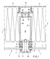
- Fig. 1 shows the cross section of a facade construction in the parapet area.
- a weather-side cover 2 of the facade consists of individual panes 4, the mutually facing free edges of which are spaced apart. Arranged at a distance from the cover 2 and thus forming an air gap, which can be closed or ventilated, is thermal insulation 6.
- This basic arrangement creates a ventilated or pressure-relieved facade construction in the parapet area.
- a holding strip 8 is provided on the outside, ie on the weather side, and sealing profiles 10 are arranged at the free ends thereof.
- the retaining strip 8 overlaps with the sealing profiles 10 the outer edge region of the individual panes 4.
- sealing profiles 12 are again provided for each side region of the individual panes 4, which are held in undercuts by plastic profiles 14.
- the end of the plastic profiles 14 facing away from the individual panes 4 is dovetail-shaped and in corresponding undercuts one Post 16 arranged.
- the spacing of the individual panes 4 from the thermal insulation 6 is accordingly determined by the arrangement of the plastic profiles 14 with the sealing profiles 12.
- the retaining strip 8 is held together with the individual disks 4, the sealing profiles 10, 12 and the plastic profiles 14 by means of a screw 18 on the post 16.
- the screw 18 is preferably made of poorly heat-conducting material, such as stainless steel. Several screws 18 are arranged in a point shape - as seen over the longitudinal extent of the post 16.
- the retaining strip 8 For receiving the screw 18, the retaining strip 8 has a corresponding bore, which is preferably designed such that the head of the screw 18 is flush with the outer surface of the retaining strip 8.
- a corresponding thread is provided in the side wall of the post 16, into which the screw 18 is screwed.
- the area between the holding strip 8 or the cover 2 and the subsequent thermal insulation 6 and the post 16 is also the first, i.e. weather-related thermal separation called.
- the post 16 is designed as a hollow profile with a rectangular cross section and can be made of aluminum, for example.
- the thermal insulation 6 directly adjoins the side walls 20, 22 of the post 16.
- the post 16 is not guided up to the room-side, ie inner termination of the thermal insulation 6, which is formed by a room-side cover 24. Rather, the post 16 already ends within the thermal insulation 6.
- the area up to the end of the thermal insulation 6 is filled by a single element 26.
- the connection between the individual element 26 and the post 16 is poorly heat-conducting and, according to the embodiment shown in FIG. 1, takes place via two insulating webs 28.
- the insulating webs 28 are preferably made of plastic.
- the single element 26 is - like the post 16 - a hollow section with a rectangular cross section, which can also be extruded from aluminum.
- the insulating webs 28 have a dovetail configuration at their edge regions 30 facing the individual element 26 or the post 16.
- the corresponding side walls of the individual element 26 or of the post 16, on which the insulating webs 28 are arranged, have corresponding undercuts.
- the supporting element of the facade or the main supporting element of the facade is consequently divided into two individual elements, namely the post 16 and the individual element 26.
- the post 16 is designed as a force-absorbing or transferring element with a static function, the connection via the insulating webs 28 to the individual element 26, as mentioned, need not constitute a static bond. If this is desired for static or other reasons, however, a static bond can be formed in the aforementioned area.
- the side wall of the individual element 26 facing the room side runs flush with the cover 24 of the thermal insulation 6 in order to form a continuous parapet area on the room side.
- the area of the entire thermal insulation is called the second, ie room-side thermal separation.
- This second thermal separation is not interrupted by the proposed poorly heat-conducting connection between the post 16 and the individual element 26 via the insulating webs 28.
- the thermal insulation properties of the facade construction shown in FIG. 1 and the following figures can thus be significantly improved.
- the cover 24 of the thermal insulation 6 arranged on the room side is bent at right angles in the area of the individual element 26 in the direction of the cover 2 and thus comes into contact with the side walls of the individual element 26. With this configuration, the second thermal separation is retained in this area or the second thermal separation is not interrupted.
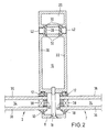
- FIG. 2 shows a further cross section of the facade construction according to Fig. 1, but in the so-called visible area, i.e. 1.
- the parts identical in FIGS. 1 and 2 have identical reference numerals.
- the weather-side cover 2 consists of double glazing 34 in the visible region.
- the individual panes 36 of the double glazing 34 are spaced apart from one another by spacers 38, the adhesive 40 of the double glazing 34 being shown on the outer edge region of the double glazing 34.
- the mutually facing edge regions of the double glazing 34 are spaced apart from one another, the double glazing 34 being arranged - like the individual panes 4 according to FIG. 1 - via the retaining strip 8, the sealing profiles 10, 12 and the screw 18 on the post 16.
- the thickness of the double glazing 34 corresponds to the thickness of the single pane 4 and that of the plastic profile 14 according to FIG. 1.
- the thermal insulation 6 according to FIG. 1 is missing, so that the side areas of the post 16 and of the individual element 26 are visible from the room side.
- the poorly heat-conducting connection between the post 16 and the individual element 26 consisting of the insulating webs 28 is also visible from the room side.
- two cover profiles 42 are clipped in the area of the connection between the post 16 and the individual element 26.
- the space for the cover profiles 42 is created in that the insulating webs 28 are not arranged in the outer edge area, but at a distance therefrom.
- the cover profiles 42 are designed such that, after they have been clipped in, they run flush with the side walls 20, 22 of the post 16 and those of the individual element 26, both of which have the same width.
- the cover profiles 42 are preferably made of plastic and can be adapted to the color of the post 16 or the individual element 26.
- the individual element 26 will not have any load-bearing properties, so that the area of the connection between the post 16 and the individual element 26 does not have to represent a static bond. In this respect, the individual element 26 could also be omitted in the visible area. Then, however, there would be a crack or a tapering visible from the room side in the area of the post 16, which is generally not desired for aesthetic reasons.
- These additional insulating glazing would preferably be arranged on the individual elements 26 by means of conventional holding structures with sealing profiles.
- the individual element 26 could, for example, have projecting brackets running parallel to the planes of the individual disks 36, the free end regions of which are designed to accommodate the corresponding seals.
- These additional insulating glazing, not shown, could on the one hand be arranged in the visible area of the facade. Such an arrangement would also be conceivable in the parapet area, in which case the insulating glazing (not shown) would then replace the thermal insulation 6 shown in FIG.
- the resulting facade construction would then correspond in an identical manner to the facade construction described in the main claim, whereby only the thermal insulation 6 would be replaced by the insulating glazing, not shown, which is mentioned here.
- the second thermal separation would then be the insulating glazing (not shown), the thermal insulation of such a facade construction being additionally influenced by the air cushion then created between the weather-side double glazing 34 and the insulating glazing, not shown.
- the design of the main support members, ie the posts 16 and the individual elements 26, would in principle be retained in this alternative design of the facade construction as it has been described for FIGS. 1 and 2 or for the following figures.
- the insulating glazing could be fixed, ie immovable, on the individual elements 26 or also openable, so that easy access to the weather-side double glazing 34 could be created.
- this proposed alternative facade construction can also be used in the parapet area. If, as is generally desired, the parapet area should continue to be opaque, this can be done by coloring the glass panes of the insulating glazing, not shown here, for example.
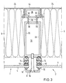
- the cover profile 44 is U-shaped in cross section and is pushed onto the individual element 26 from the room side or attached, so that the room side facing side wall and the side walls of the individual element 26 facing the thermal insulation 6 are covered.
- the outer dimensions - seen in the direction of the thermal insulation 6 - are made narrower than the corresponding dimensions of the post 16 by twice the thickness of the webs of the cover profile 44.
- FIG. 4 shows the cross section corresponding to FIG. 3, but not - as in FIG. 3 - in the parapet area but in the visible area.
- identical parts are provided with identical reference numbers.
- cover profile 44 While it is not necessary in the parapet area for the free ends of the cover profile 44 to extend to the post 16, this is desirable in the visible area in order to cover or cover the area of the connection between the post 16 and the individual element 26. However, it is also possible to design the cover profile 44 in the parapet area with longer webs, as shown in FIG. 4.
- the cover profile 44 can in turn be made of plastic and the color of the post 16 can be adapted.
- FIG. 5 shows a cross section through a further embodiment of a facade construction, which essentially corresponds to the facade construction according to FIG. 1. Identical parts are again identified with identical train numbers.
- FIG. 5 Different from FIG. 5 is the fastening of the retaining strip 8 to the corresponding side wall of the post 16. It is not carried out — as in FIG. 1 — via a screw 18, but via an insulating web 46.
- the insulating web 46 has - like the insulating webs 28 -
- the post 16 or the retaining strip 8 facing, dovetail-shaped edge regions 48.
- there are 16 undercuts in the retaining strip 8 and the corresponding side wall of the post provided for receiving the edge regions 48 of the insulating web 46.
Landscapes
- Engineering & Computer Science (AREA)
- Architecture (AREA)
- Civil Engineering (AREA)
- Structural Engineering (AREA)
- Physics & Mathematics (AREA)
- Electromagnetism (AREA)
- Building Environments (AREA)
- Soil Working Implements (AREA)
- Curtains And Furnishings For Windows Or Doors (AREA)
- Details Of Television Scanning (AREA)
- Liquid Crystal (AREA)
Description
- Die Erfindung betrifft eine Fassadenkonstruktion wie sie im Anspruch 1 beschrieben ist.
- Bei Fassadenkonstruktionen von Gebäuden mit metallischen Tragprofilen wird zur Vermeidung von Wärmeverlusten die äußere Abdeckung bzw. die Außenschale über eine schlecht wärmeleitende Konstruktion mit den Tragprofilen der Fassade haltend verbunden. Bei der äußeren Abdeckung kann es sich unter anderem um eine Verglasung oder auch andere für Fassaden übliche Elemente, wie eine Einfach- oder Isolierverglasung oder Paneele, handeln. Die schlecht wärmeleitende Konstruktion zwischen der Abdeckung und den Tragprofilen der Fassade verhindert dabei das Entstehen einer Kältebrücke. Der Bereich der schlecht wärmeleitenden Konstruktion wird auch als erste Dämmzone bezeichnet. Eine zweite Dämmzone ergibt sich im Bereich der Brüstungen durch die Anordnung einer Wärmedämmung. Die Wärmedämmung wird durch die metallischen Tragprofile der Fassade jedoch unterbrochen, die häufig aus Aluminium-Hohlprofilen bestehen. Der raumseitige Abschluß der Tragprofile verläuft im Regefall bündig zur raumseitigen Abdeckung der Wärmedämmung. Die Wärmedämmung wird bei solchen Fassadenkonstruktionen auch als zweite Dämmzone bezeichnet.
- Bei diesen bekannten Fassadenkonstruktionen besteht somit der Nachteil, daß die zweite Dämmzone im Bereich der tragenden Elemente der Fassade unterbrochen wird und demzufolge im Verlauf der zweiten Dämmzone eine Unterbrechung bzw. ein Sprung in der Wärmedämmebene entsteht.
- Zur Vermeidung dieses Nachteils schlägt die DE 35 09 466 A1 vor, die Haupttragglieder der Fassade in drei voneinander unabhängige Einzelelemente zu unterteilen, wobei diese Einzelelemente über schlecht wärmeleitende Verbindungen miteinander verbunden sind. Die Unterbrechung der Haupttragglieder der Fassade, soll eine zweite Dämmzone auch im Bereich dieser Elemente schaffen. Im Bereich zwischen den Haupttraggliedern der Fassade besteht die erste thermische Trennung entweder aus einem Rolladen mit seitlichen Nuten, die auf Stegen des äußeren Einzelelements geführt sind, oder einer Klappe, die einer an dem Steg gehaltenen Dichtung anliegt. Die zweite thermische Trennung besteht aus einer Isolierverglasung. Bei dieser bekannten Fassadenkonstruktion läßt sich zeitweilig die ununterbrochene Anordnung zweier hintereinander liegender thermischer Trennungen herstellen, nämlich bei geschlossener Klappe oder geschlossenen Rolladen.
- Die Wärmedämmung in der ersten Dämmzone liegt dabei unmittelbar der Abdeckung an.
- Aus der W0/03 733 ist es gleichfalls bekannt, zur Verbesserung der Wärmedämmung bei einer Fassadenkonstruktion die Haupttragglieder mehrteilig auszuführen, wobei diese durch schlecht wärmeleitende Isolierstege verbunden sind. Der Aufbau einer ersten und zweiten Dämmzone im Brüstungsbereich zwischen den Haupttraggliedern ist nicht vorgesehen.
- Die DE 18 15 528 A1 zeigt eine Blendwandkonstruktion mit hinsichtlich der Wärmedämmung gegenüber den vorgenannten Druckschriften einfacherem Aufbau mit einer Dämmzone, in der die Wärmedämmung der wetterseitigen Abdeckung unmittelbar anliegt. Das Profil der Tragglieder ist dabei so gestaltet, an der Rückseite der Abdeckung kondensierende Feuchtigkeit einem Abzugssystem zugeführt wird, mit dem diese auf die Außenseite der Fassade transportiert wird. Um zu verhindern, daß bei hohem Winddruck und starkem Regen von außen Feuchtigkeit in das Abzugssystem eingedrückt werden kann, ist wetterseitig vor einem fortlaufenden offenen Schlitz ein Wandelement angebracht, daß nach unten offen ist und einen schräg zur Abdeckung weisenden Steg aufweist. Die offene untere Seite des Wandelements verhindert, daß sich Wasser ansammelt oder in den Raum zwischen das Wandelement und der Abdeckung eindringen kann. Darüberhinaus hat diese offene Konstruktion eine druckausgleichende Wirkung auf die Luft innerhalb dieses Raumes.
- Es ist Aufgabe der vorliegenden Erfindung, die Wärmedämmungseigenschaften von Fassaden, insbesondere im Bereich der Brüstung, weiter zu verbessern.
- Die Aufgabe wird durch die im Anspruch 1 angegebenen Merkmale gelöst.
- Der Grundgedanke der Erfindung besteht in der weiteren Optimierung der Ausbildung und der Anordnung der Dämmzonen relativ zueinander, wodurch der Wärmeübergang von der Wetterseite zur Raumseite der Fassadenkonstruktion infolge der isolierenden Wirkung der Luftschicht zwischen den Dämmzonen weiter verringert ist. Dies wird erreicht, ohne die Haupttragglieder der Fassade aufwendiger, und damit in der Herstellung kostenintensiver zu gestalten. Bei der druckentspannten Ausbildung des Luftspaltes werden lediglich kleine Bereiche, beispielsweise im Bereich der Dichtungen, ausgeschnitten und dabei kleine Kanäle gebildet. Sofern die Luftspalte die erste thermische Trennung darstellt, darf durch die druckentspannte Ausbildung die wärmedämmende Wirkung des Luftspaltes nicht erheblich negativ beeinflußt werden, was durch die vorgenannten kleinen Kanäle erreicht werden kann.
- Zumindest ein Einzelelement des Haupttraggliedes muß kräfteaufnehmend bzw. -abtragend, d. h. statisch wirkend, im Sinne eines Haupttraggliedes ausgebildet sein. Abhängig von dem jeweiligen Erfordernis können das bzw. die weiteren Einzelelemente entweder ebenfalls statisch wirkend oder nicht kräfteaufnehmend bzw. kräfteabtragend ausgebildet sein. Die Verbindung zwischen den Einzelelementen kann dann den Erfordernissen entsprechend ausgelegt werden, nämlich ggf. kräfteübertragend oder nichtübertragend wirken.
- Bei der vorgeschlagenen Fassadenkonstruktion ist es insbesondere vorteilhaft, daß die Wärmedämmung lediglich eine raumseitige Abdeckung aufweisen muß. Die Abdeckung kann aus Blech oder ähnlichen Materialien bestehen und stellt die Dampfsperre bzw. Dampfbremse dar. Anders als bei üblichen Wärmedämmungen in Form von Paneelen, die üblicherweise zwei Deckschalen bzw. Abdeckungen aufweisen und als selbsttragende Elemente ausgebildet sind, bedarf es bei der vorliegenden Fassadenkonstruktion nur der raumseitigen Abdeckung der Wärmedämmung.
- Zur weiteren Optimierung der wärmedämmenden Eigenschaften der zweiten thermischen Trennung ist die raumseitige Abdeckung der Wärmedämmung, zu deren Halterung an dem raumseitigen Einzelelement des Haupttraggliedes angeschlossen. Somit wird sichergestellt, daß die Abdeckung nicht etwa mit dem, mit der ersten thermischen Trennung in Verbindung stehenden Einzelelement einen Kontakt aufweist und so die Wärmedämmung der vorgschlagenen Fassadenkonstruktion negativ beeinflussen würde.
- Zweckmäßigerweise ist die Abdeckung der Wärmedämmung mit dem raumseitigen Einzelelement des Haupttragglieds fluchtend ausgebildet. Es kann somit raumseitig eine durchgehende Fläche bzw. Ebene erzeugt werden. Von der Wärmedämmung aus in den Raum hineinragende Einzelelemente oder von der Wärmedämmung nach außen gesehen zurückspringende Einzelelemente können somit, insbesondere aus ästethischen Gründen, vermieden werden.
- Die schlecht wärmeleitende Verbindung zwischen den Einzelelementen kann vorzugsweise als stegartige oder auch als punktförmige Anbindung ausgebildet sein. Die Wahl der entsprechenden Anbindung hängt unter anderem davon ab, ob spielsweise auch das raumseitige Einzelelement kräfteaufnehmend bzw. -abtragend ausgebildet sein soll oder ob ein statischer Verbund im Bereich der schlecht wärmeleitenden Verbindung nicht vorgesehen ist.
- Sofern eine stegartige Anbindung gewählt wird, besteht die schlecht wärmeleitende Verbindung vorzugsweise aus wenigstens einem Isoliersteg bzw. einer Isolierschiene. Dabei kann der Isoliersteg aus Kunststoff oder anderen schlecht wärmeleitenden Materialien hergestellt sein.
- Vorzugsweise wird der Isoliersteg mit seinen freien Rändern formschlüssig in an den Einzelelementen ausgebildete Hinterschneidungen schubfest oder gleitend eingreifen und dazu vorzugsweise einen schwalbenschwanzförmigem Querschnitt in den freien Randbereichen aufweisen. Die entsprechenden Hinterschneidungen an den Einzelelementen sind insbesondere dann leicht herstellbar, wenn die Einzelemente aus Aluminiumprofilen stranggepreßt werden. Üblicherweise wird es sich bei den Einzelelementen um hohlprofilartige Elemente handeln. Bei der schubfesten Ausbildung besteht der Vorteil in der höheren Steifigkeit des gesamten Haupttraggliedes. Der Nachteil kann unter Umständen in dem sog. Bimetalleffekt liegen, da sich das raumseitige sowie das wetterseitige Einzelelement insbesondere bei niedrigen Außentemperaturen, unterschiedlich erwärmen und somit unterschiedlich ausdehnen und sich dann Verbiegungen des Haupttraggliedes einstellen können. Bei der gleitenden Ausbildung entsteht teilhafterweise ein solcher Bimetalleffekt nicht, wobei hier das Haupttragglied dafür eine geringere Steifigkeit aufweist, da beispielsweise nur das wetterseitig angeordnete Einzelelement kräfteaufnehmend bzw. -abtragend ausgebildet ist, da das raumseitige Einzelelement dann keinen Beitrag zur Tragwirkung leistet.
- Die schlecht wärmeleitende Konstruktion, über welche die entsprechende Abdeckung mit den Haupttragglieden verbindbar ist, kann vorzugsweise als punktförmige Anbindung ausgebildet sein. Über die Länge des entsprechenden Hauptraggliedes sind dann mehrere solche, voneinander beabstandeter punktförmiger Anbindungen vorhanden.
- Sofern die punktförmige Anbindung gewählt wird, besteht die schlecht wärmeleitende Konstruktion vorzugsweise im wesentlichen aus der Halterung der wetterseitigen Abdeckung an dem Haupttragglied, insbesondere in Form einer Schraube aus vorzugsweise Edelstahl, sowie zwischen der wetterseitigen Abdeckung und dem Haupttragglied angeordneten Dichtungs- und Kunststoffprofilen oder Kunststoffdistanzprofilen. Somit besteht zwar eine Verbindung zwischen der wetterseitigen Abdeckung und dem Haupttragglied. Die schlecht wärmeleitenden Eigenschaften der Edelstahlschrauben sowie der verwendeten Profile sowie die zwischen wetterseitiger Abdeckung und Haupttragglied vorhandene Luft stellen jedoch in ausreichender Weise den Bereich der ersten thermischen Trennung dar.
- Sofern Schrauben verwendet werden, ist es zweckmäßig, das entsprechende Einzelelement zur Anordnung der Schraube mit Durchgängen oder Bohrungen zu versehen bzw. Gewinde oder Gewindehülsen bei dem Einzelelement vorzusehen.
- Vor allem auch aus ästhetischen Gründen ist der Bereich der schlecht wärmeleitenden Verbindung zwischen den Einzelelementen raumseitig nicht einsehbar ausgebildet. Dies wird im Brüstungsbereich durch die bündige Ausgestaltung des raumseitigen Einzelelements mit der Wärmedämmung erreicht. Im sichtbaren Bereich ist jedoch eine Wärmedämmung bzw. eine raumseitige Isolierverglasung nicht vorhanden, so daß der Bereich der Verbindungen zwischen den Einzelelementen sichtbar wäre.
- Um diese raumseitige Nichteinsehbarkeit zu ereichen, kann der Bereich der Verbindung zwischen den Einzelelementen vorzugsweise ein Abdeckprofil aufweisen.
- Ein solches Abdeckprofil kann seitlich in dem Bereich der Verbindung zwischen den Einzelelementen angeordnet, insbesondere eingeclipst sein und dabei insbesondere mit den entsprechenden Flächen der Einzelemente bündig verlaufen.
- Das Abdeckprofil kann jedoch auch das raumseitig sichtbare Einzelelement sowie den Verbindungsbereich an sich vollständig überdecken bzw. abdecken. Ein solches Abdeckprofil würde dann beispielsweise im Querschnitt U-förmig ausgebildet sein und kann auf das raumseitige Einzelelement in einfacher Weise aufgeclips bzw. aufgeschoben werden.
- Die vorgeschlagenen Abdeckprofile bestehen Zweckmäßigerweise aus Kunststoff. Die angestrebte thermische Trennung bleibt somit erhalten. Die Abdeckprofile können auch an die farbliche Ausgestaltung der Einzelelemente oder der Verkleidung der Wärmedämmung angepaßt sein. Farbwünsche können im weitesten Sinn somit Berücksichtigung finden.
- Die wetterseitige Abdeckung ist vorzugsweise über ihre Randbereiche übergreifende Halteleisten mit an diesen angeordneten Dichtungsprofilen an den Haupttraggliedern gehalten.
- Zwischen der wetterseitigen Abdeckung und den Haupttraggliedern sind vorzugsweise schlecht wärmeleitende Abstandhalter mit an diesen angeordneten Dichtungsprofilen vorgesehen. Die Abstandhalter sind dabei zweckmäßigerweise aus Kunststoff oder anderen schlecht wärmeleitenden Materialien hergestellt.
- Die Halteleiste selbst ist vorzugsweise über Edelstahlschrauben an den Haupttraggliedern der Fassade befestigt. Die zwischen der Halteleiste und den Abstandhaltern über die Dichtungsprofile eingeklemmte wetterseitige Abdeckung kann somit sicher an den Haupttraggliedern der Fassade gehalten werden.
- Es ist allerdings auch möglich, die Halteleiste über ein schlecht wärmeleitendes stegartiges Teil, insbesondere einen Isoliersteg oder eine Isolierschiene, an den Haupttraggliedern der Fassade zu befestigen. Dazu wird der Isoliersteg wiederum eine besondere Ausgestaltung in den Randbereichen, z.B. eine schwalbenschwanzförmige Ausgestaltung, aufweisen. An der Halteleiste und den gegenüberliegenden Haupttraggliedern der Fassade sind dann entsprechende Hinterschneidungen vorgesehen. Die Abdeckung kann alternativ auch über tragende Verklebungen an dem entsprechenden Haupttragglied angeordnet sein. Die anstelle der Abstandhalter dann vorgesehene Verklebung ist aufgrund ihres Materials schlecht wärmeleitend.
- Nachfolgend soll die Erfindung in beispielhafter Weise anhand einiger bevorzugter Ausführungsbeispiele erläutert werden. Es zeigen dabei:
- Fig. 1:
- einen Querschnitt durch eine Fassadenkonstruktion im Brüstungsbereich,
- Fig. 2:
- einen Querschnitt entsprechend Fig. 1 im sichtbaren Bereich,
- Fig. 3:
- einen Querschnitt durch eine andere Ausgestaltung der Fassadenkonstruktion im Brüstungsbereich,
- Fig. 4:
- einen Querschnitt entsprechend Fig. 3 im sichtbaren Bereich und
- Fig. 5:
- einen Querschnitt durch eine weitere Fassadenkonstruktion im Brüstungsbereich.
- Fig. 1 zeigt den Querschnitt einer Fassadenkonstruktion im Brüstungsbereich. Eine wetterseitige Abdeckung 2 der Fassade besteht aus Einzelscheiben 4, deren einander zugewandte freie Ränder voneinander beabstandet sind. Von der Abdeckung 2 beabstandet angeordnet und somit einen Luftspalt, der abgeschlossen oder belüftet sein kann, bildend ist eine Wärmedämmung 6. Durch diese grundlegende Anordnung wird eine hinterlüftete oder druckentspannte Fassadenkonstruktion im Brüstungsbereich geschaffen. Im Bereich der freien Ränder der Einzelscheiben 4 ist außen, d.h. auf der Wetterseite, eine Halteleiste 8 vorgesehen, an deren freien Enden Dichtungsprofile 10 angeordnet sind. Die Halteleiste 8 übergreift mit den Dichtungsprofilen 10 den äußeren Randbereich der Einzelscheiben 4. Auf der Innenseite der Einzelscheiben 4, d.h. auf der Raumseite, sind für jeden Seitenbereich der Einzelscheiben 4 wiederum Dichtungsprofile 12 vorgesehen, die in Hinterschneidungen von Kunststoffprofilen 14 gehalten sind. Das den Einzelscheiben 4 abgewandte Ende der Kunststoffprofile 14 ist schwalbenschwanzförmig ausgebildet und in entsprechenden Hinterschneidungen eines Pfostens 16 angeordnet. Die Beabstandung der Einzelscheiben 4 von der Wärmedämmung 6 wird demnach durch die Anordnung der Kunststoffprofile 14 mit den Dichtungsprofilen 12 festgelegt. Die Halteleiste 8 wird zusammen mit den Einzelscheiben 4, den Dichtungsprofilen 10, 12 sowie den Kusntstoffprofilen 14 über eine Schraube 18 am Pfosten 16 gehalten. Die Schraube 18 besteht vorzugsweise aus schlecht wärmeleitendem Material, wie beispielsweise Edelstahl. Mehrere Schrauben 18 sind punktförmig - über die Längserstreckung des Pfostens 16 gesehen - angeordnet. Zur Aufnahme der Schraube 18 weist die Halteleiste 8 eine entsprechende Bohrung auf, die vorzugsweise so ausgestaltet ist, daß der Kopf der Schraube 18 bündig mit der Außenfläche der Halteleiste 8 verläuft. In der Seitenwand des Pfostens 16, in welcher die Schraube 18 eingeschraubt ist, ist ein entsprechendes Gewinde vorgesehen.
- Der Bereich zwischen der Halteleiste 8 bzw. der Abdeckung 2 und der anschließenden Wärmedämmung 6 und dem Pfosten 16 wird auch als erste, d.h. wetterseitige thermische Trennung bezeichnet.
- Der Pfosten 16 ist als Hohlprofil mit rechteckigem Querschnitt ausgebildet und kann bespielsweise aus Aluminium bestehen. An den Seitenwänden 20, 22 des Pfostens 16 schließt sich direkt die Wärmedämmung 6 an. Der Pfosten 16 ist jedoch nicht bis zum raumseitigen, d.h. inneren Abschluß der Wärmedämmung 6 geführt, der durch eine raumseitige Abdeckung 24 gebildet wird. Vielmehr endet der Pfosten 16 bereits innerhalb der Wärmedämmung 6. Der Bereich bis zum Abschluß der Wärmedämmung 6 wird von einem Einzelelement 26 ausgefüllt. Die Verbindung zwischen dem Einzelelement 26 und dem Pfosten 16 ist schlecht wärmeleitend ausgebildet und erfolgt gemäß der in Fig. 1 vorliegenden Ausführungsform über zwei Isolierstege 28. Die Isolierstege 28 sind vorzugsweise aus Kunststoff hergestellt. Bei dem Einzelelement 26 handelt es sich - wie bei dem Pfosten 16 - um ein im Querschnitt rechteckiges Hohlprofil, welches ebenfalls aus Aluminium stranggepreßt sein kann. Die Isolierstege 28 weisen an ihren, dem Einzelelement 26 bzw. dem Pfosten 16 zugewandten Randbereichen 30 eine schwalbenschwanzförmige Konfiguration auf. Die entsprechenden Seitenwandungen des Einzelelements 26 bzw. des Pfostens 16, an denen die Isolierstege 28 angeordnet sind, weisen entsprechende Hinterschneidungen auf. Das tragende Element der Fassade bzw. das Haupttragglied der Fassade ist folglich in zwei Einzelelemente, nämlich den Pfosten 16 und das Einzelelement 26, aufgeteilt.
- Fig. 1 zeigt, daß das Einzelelement 26 und der Pfosten 16 voneinander beabstandet angeordnet sind, wobei durch die Isolierstege 28 eine schubfeste oder gleitende Verbindung hergestellt werden kann. Der Pfosten 16 ist als kräfteaufnehmendes bzw. -abtragendes Element mit statischer Funktion ausgebildet, wobei die Verbindung über die Isolierstege 28 an das Einzelelement 26, wie erwähnt, keinen statischen Verbund darstellen muß. Falls dies aus statischen oder anderen Gründen jedoch gewünscht ist, kann jedoch ein statischer Verbund in dem vorgenannten Bereich ausgebildet werden. Die der Raumseite zugewandte Seitenwandung des Einzelelements 26 verläuft bündig mit der Abdeckung 24 der Wärmedämmung 6, um einen durchgehenden Brüstungsbereich auf der Raumseite zu bilden.
- Der Bereich der gesamten Wärmedämmung wird als zweite , d.h. raumseitige thermische Trennung bezeichnet. Diese zweite thermische Trennung wird durch die vorgeschlagene schlecht wärmeleitende Verbindung zwischen dem Pfosten 16 und dem Einzelement 26 über die Isolierstege 28 nicht unterbrochen. Die wärmedämmenden Eigenschaften der in Fig. 1 und den folgenden Figuren gezeigten Fassadenkonstruktion können somit wesentlich verbessert werden.
- Die auf der Raumseite angeordnete Abdeckung 24 der Wärmedämmung 6 ist im Bereich des Einzelelements 26 rechtwinklig in Richtung auf die Abdeckung 2 hin abgebogen und kommt somit an den Seitenwandungen des Einzelelements 26 zur Anlage. Durch diese Ausgestaltung bleibt die zweite thermische Trennung in diesem Bereich erhalten bzw. wird die zweite thermische Trennung nicht unterbrochen.
- Fig. 2 zeigt einen weiteren Querschnitt der Fassadenkonstruktion gemäß Fig. 1, jedoch im sogenannten sichtbaren Bereich, d.h. oberhalb des Brüstungsbereiches gemäß Fig. 1. Die in den Fig. 1 und 2 identischen Teile weisen identische Bezugsziffern auf.
- Die wetterseitige Abdeckung 2 besteht im sichtbaren Bereich aus einer Doppelverglasung 34. Die Einzelscheiben 36 der Doppelverglasung 34 sind über Abstandhalter 38 voneinander beabstandet, wobei am äußeren Randbereich der Doppelverglasungen 34 die Verklebung 40 der Doppelverglasung 34 gezeigt ist. Die einander zugewandten Randbereiche der Doppelverglasung 34 sind voneinander beabstandet, wobei die Doppelverglasung 34 im übrigen - wie die Einzelscheiben 4 gemäß Fig. 1 - über die Halteleiste 8, die Dichtungsprofile 10, 12 und die Schraube 18 am Pfosten 16 angeordnet sind. Die Dicke der Doppelverglasung 34 entspricht in ihrem Betrag der Dicke der Einzelscheibe 4 sowie der des Kunststoffprofils 14 gemäß Fig. 1.
- Im sichtbaren Bereich fehlt die Wärmedämmung 6 gemäß Fig. 1, so daß die Seitenbereiche des Pfostens 16 sowie des Einzelelements 26 von der Raumseite her sichtbar sind. Damit ist allerdings auch die aus den Isolierstegen 28 bestehende schlecht wärmeleitende Verbindung zwischen dem Pfosten 16 und dem Einzelelement 26 von der Raumseite her sichtbar. Da dies aus ästhetischen Gründen im Regelfall nicht gewünscht ist, sind zwei Abdeckprofile 42 in dem Bereich der Verbindung zwischen dem Pfosten 16 und dem Einzelelement 26 eingeclipst. Der Raum für die Abdeckprofile 42 wird dadurch geschaffen, daß die Isolierstege 28 nicht im äußeren Randbereich, sondern von diesem beabstandet angeordnet sind. Die Abdeckprofile 42 sind so ausgebildet, daß sie nach dem Einclipsen bündig mit den Seitenwänden 20, 22 des Pfostens 16 sowie denen des Einzelelements 26 verlaufen, die beide die gleiche Breite aufweisen. Die Abdeckprofile 42 bestehen vorzugsweise aus Kunststoff und können an die farbliche Ausgestaltung des Pfostens 16 bzw. des Einzelelements 26 angepaßt werden.
- Im Regelfall wird das Einzelelement 26 keine tragenden Eigenschaften aufweisen, so daß der Bereich der Verbindung zwischen dem Pfosten 16 und dem Einzelelement 26 keinen statischen Verbund darstellen muß. Insoweit könnte das Einzelelement 26 im sichtbaren Bereich auch weggelassen werden. Dann würde jedoch ein von der Raumseite her sichtbarer Sprung bzw. eine Verjüngung im Bereich des Pfostens 16 auftreten, was aus ästhetischen Gründen im Regelfall nicht gewünscht ist.
- Eine nicht dargestellt Alternative besteht in der Anordnung von weiteren raumseitigen Isolierverglasungen im Bereich zwischen den Hauptträgern, d.h. zwischen den Pfosten 16 sowie den Einzelelementen 26. Vorzugsweise wären diese weiteren Isolierverglasungen an den Einzelelementen 26 mittels üblicher Haltekonstruktionen mit Dichtprofilen angeordnet. Dazu könnte das Einzelelement 26 beispielsweise parallel zu den Ebenen der Einzelscheiben 36 verlaufende, auskragende Halterungen aufweisen, deren freie Endbereiche zur Aufnahme der entsprechenden Dichtungen ausgebildet sind. Diese zusätzlichen, nicht dargestellten Isolierverglasungen könnten einerseits im sichtbaren Bereich der Fassade angeordnet werden. Aber auch im Brüstungsbereich wäre eine solche Anordnung denkbar, wobei diese nicht dargestellten Isolierverglasungen dann die in Figur 1 gezeigte Wärmedämmung 6 ersetzen würde. Die somit entstehende Fassadenkonstruktion würde dann in identischer Weise der im Hauptansruch beschriebenen Fassadenkonstruktion entsprechen, wobei lediglich die Wärmedämmung 6 durch die hier angesprochenen, nicht dargestellten Isolierverglasungen ersetzt werden würde. Die zweite thermische Trennung wäre dann die nicht dargestellte Isolierverglasung, wobei die Wärmedämmung einer solchen Fassadenkonstruktion noch zusätzlich durch das dann entstehende Luftpolster zwischen der wetterseitigen Doppelverglasung 34 und der nicht dargestellten Isolierverglasung positiv beeinflußt wird. Die Ausgestaltung der Haupttragglieder, d.h. der Pfosten 16 sowie der Einzelelemente 26, würde bei dieser alternativen Ausgestaltungsform der Fassadenkonstruktion grundsätzlich so beibehalten werden, wie sie zu Figur 1 und 2 beschrieben worden ist bzw. zu den nachfolgenden Figuren beschrieben wird. Die nicht dargestellten Isolierverglasungen könnten fest d.h. unbeweglich an den Einzelelementen 26 angeordnet sein oder auch öffenbar, so daß ein leichter Zugang zu den wetterseitigen Doppelverglasungen 34 geschaffen werden könnte. Diese vorgeschlagene alternative Fassadenkonstruktion kann, wie erwähnt, ebenfalls im Brüstungsbereich eingesetzt werden. Sofern, wie es im Regelfall gewünscht sein wird, der Brüstungsbereich weiterhin undurchsichtig ausgebildet werden soll, kann dies durch entsprechende Einfärbung beispielsweise der Glasscheiben der hier nicht dargestellten Isolierverglasung erfolgen.
- Fig. 3 entspricht grundlegend dem Querschnitt gemäß Fig.1. Identische Teile sind wiederum mit identischen Bezugsziffern versehen.
- Unterschiedlich ist lediglich die Anordnung eines anderen Abdeckprofils 44 im Bereich des Einzelelements 26 bzw. der Verbindung zwischen dem Einzelelement 26 und dem Pfosten 16. Das Abdeckprofil 44 ist im Querschnitt U-förmig ausgebildet und wird von der Raumseite her auf das Einzelelement 26 aufgeschoben bzw. aufgesteckt, so daß die der Raumseite zugewandte Seitenwandung sowie die der Wärmedämmung 6 zugewandten Seitenwandungen des Einzelelements 26 abgedeckt sind. Dazu sind die Außenabmessungen - in Richtung der Wärmedämmungen 6 gesehen - um die doppelte Stärke der Stege des Abdeckprofils 44 schmäler ausgebildet als die entsprechenden Abmessungen des Pfostens 16.
- Fig. 4 stellt den der Fig. 3 entsprechenden Querschnitt dar, jedoch nicht - wie bei Fig. 3 - im Brüstungsbereich sondern im sichtbaren Bereich. Identische Teile sind auch hier mit identischen Bezugsziffern versehen.
- Während es im Brüstungsbereich nicht erforderlich ist, daß sich die freien Enden des Abdeckprofils 44 bis zum Pfosten 16 erstrecken, ist dies im sichtbaren Bereich gewünscht, um den Bereich der Verbindung zwischen dem Pfosten 16 und dem Einzelelement 26 zu verdecken bzw. abzudecken. Es ist jedoch auch möglich, das Abdeckprofil 44 im Brüstungsbereich mit längeren Stegen - wie in Fig. 4 gezeigt - auszubilden. Das Abdeckprofil 44 kann wiederum aus Kunststoff hergestellt und in seiner farblichen Ausgestaltung dem Pfosten 16 angepaßt sein.
- Schließlich zeigt Fig. 5 einen Querschnitt durch eine weitere Ausführungsform einer Fassadenkonstruktion, die im wesentlichen der Fassadenkonstruktion gemäß Fig. 1 entspricht. Identische Teile sind wiederum mit identischen zugsziffern bezeichnet.
- Unterschiedlich in Fig. 5 ist die Befestigung der Halteleiste 8 an der entsprechenden Seitenwand des Pfostens 16. Sie erfolgt nicht - wie in Fig. 1 - über eine Schraube 18, sondern über einen Isoliersteg 46. Der Isoliersteg 46 weist - wie auch die Isolierstege 28 - dem Pfosten 16 bzw. der Halteleiste 8 zugewandte, schwalbenschwanzförmig ausgebildete Randbereiche 48 auf. Entsprechend sind in der Halteleiste 8 sowie der entsprechenden Seitenwandung des Pfostens 16 Hinterschneidungen zur Aufnahme der Randbereiche 48 des Isolierstegs 46 vorgesehen.
-
- 2
- wetterseitige Abdeckung
- 4
- Einzelscheibe
- 6
- Wärmedämmung
- 8
- Halteleiste
- 10
- Dichtungsprofil
- 12
- Dichtungsprofil
- 14
- Kunststoffprofil
- 16
- Pfosten
- 18
- Schraube
- 20
- Seitenwand
- 22
- Seitenwand
- 24
- raumseitige Abdeckung
- 26
- Einzelelement
- 28
- Isoliersteg
- 30
- Randbereich
- 34
- Doppelverglasung
- 36
- Einzelscheibe
- 38
- Abstandhalter
- 40
- Verklebung
- 42
- Abdeckprofil
- 44
- Abdeckprofil
- 46
- Isoliersteg
- 48
- Randbereich
Claims (21)
- Fassadenkonstruktion, bei welcher ununterbrochen im gesamten Brüstungsbereich, insbesondere auch zwischen den tragenden Elementen der Fassade bzw. den Haupttraggliedern, wie beispielsweise den Pfosten (16) oder Riegeln, eine erste außenliegende, d. h. wetterseitige thermische Trennung sowie eine zweite innenliegende, d. h. raumseitige thermische Trennung angeordnet ist, wobei zwischen den Haupttraggliedern wetterseitig eine Abdeckung (2) oder eine isolierende Abdeckung oder eine Isolierverglasung, jeweils mit anschließendem Luftspalt, der abgeschlossen oder druckentspannt ist, sowie raumseitig eine Wärmedämmung (6) mit Abdeckung (24) oder eine Isolierverglasung angeordnet ist und die Haupttragglieder wetterseitig über eine schlecht wärmeleitende Konstruktion (18, 12, 14) mit der entsprechenden Abdeckung (2) verbindbar sind und aus wenigstens zwei voneinander beabstandeten Einzelelementen (16, 26) bestehen, die über weitere schlecht wärmeleitende Verbindungen (28) miteinander verbunden sind.
- Fassadenkonstruktion nach Anspruch 1, bei welcher wenigstens ein Einzelelement (16) im Sinne eines Haupttraggliedes kräfteaufnehmend bzw. kräfteabtragend ausgebildet ist.
- Fassadenkonstruktion nach Anspruch 1, bei welcher die Wärmedämmung (6) lediglich eine raumseitige Abdeckung (24) aufweist.
- Fassadenkonstruktion nach Anspruch 1 oder 3, bei welcher die raumseitige Abdeckung (24) der Wärmedämmung (6) zu deren Halterung an dem raumseitigen Einzelelement (26) des Haupttraggliedes angeschlossen ist.
- Fassadenkonstruktion nach einem der Ansprüche 3 oder 4, bei welcher die Abdeckung (24) der Wärmedämmung (6) mit dem raumseitigen Einzelelement (26) des Haupttragglieds fluchtend ausgebildet ist.
- Fassadenkonstruktion nach Anspruch 1, bei welcher die schlecht wärmeleitende Verbindung als stegartige Anbindung ausgebildet ist.
- Fassadenkonstruktion nach Anspruch 1 oder 6, bei welcher die schlecht wärmeleitende Verbindung aus wenigstens einem Isoliersteg (28) bzw. einer Isolierschiene besteht.
- Fassadenkonstruktion nach Anspruch 7, bei welcher der Isoliersteg (28) mit seinen freien Rändern formschlüssig in an den Einzelelementen (16, 26) ausgebildete Hinterschneidungen schubfest oder gleitend eingreift.
- Fassadenkonstruktion nach Anspruch 1, bei welcher die schlecht wärmeleitende Konstruktion als punktförmige Anbindung ausgebildet ist.
- Fassadenkonstruktion nach Anspruch 1 oder 9, bei welcher die schlecht wärmeleitende Konstruktion aus der Halterung der wetterseitigen Abdeckung (2) an dem Hauptragglied, insbesondere in Form einer Schraube (18) vorzugsweise aus Edelstahl, sowie zwischen der wetterseitigen Abdeckung (2) und dem Haupttragglied angeordneten Dichtungs- (12) und Kunststoffprofilen (14) oder Kunststoffdistanzprofilen besteht.
- Fassadenkonstruktion nach Anspruch 10, bei welcher das entsprechende Einzelelement (16) zur Anordnung der Schraube (18) Durchgänge bzw. Gewinde oder Gewindehülsen aufweist.
- Fassadenkonstruktion nach Anspruch 1, bei welcher die schlecht wärmeleitende Verbindung zwischen den Einzelelementen (16, 26) von der Raumseite her nicht einsehbar ausgebildet ist.
- Fassadenkonstruktion nach Anspruch 14, bei welcher der Bereich der Verbindung ein Abdeckprofil (42; 44) aufweist.
- Fassadenkonstruktion nach Anspruch 12 oder 13, bei welcher das Abdeckprofil (42) seitlich in dem Bereich der Verbindung angeordnet ist und insbesondere mit den entsprechenden Flächen der Einzelelemente (16, 26) bündig verläuft.
- Fassadenkonstruktion nach Anspruch 13 oder 14, bei welcher das Abdeckprofil (44) das raumseitig sichtbare Einzelelement (26) sowie den Bereich der Verbindung an sich vollständig überdeckt bzw. abdeckt.
- Fassadenkonstruktion nach einem der Ansprüche 13 bis 15, bei welcher die Abdeckprofile (42; 44) aus Kunststoff bestehen.
- Fassadenkonstruktion nach einem der Ansprüche 13 bis 16, bei welcher die Abdeckprofile (42; 44) der farblichen Ausgestaltung der Einzelelemente (16, 26) oder der raumseitigen Abdeckung (24) der Wärmedämmung (6) angepaßt sind.
- Fassadenkonstruktion nach einem der Ansprüche 1 bis 17, bei welcher die wetterseitige Abdeckung (2) über ihre Randbereiche übergreifende Halteleisten (8) mit an diesen angeordneten Dichtungsprofilen (10) an den Haupttraggliedern gehalten sind.
- Fassadenkonstruktion nach einem der Ansprüche 1 bis 18, bei welcher zwischen der wetterseitigen Abdeckung (2) und den Haupttraggliedern schlecht wärmeleitende Abstandhalter (14) mit an diesen angeordneten Dichtungsprofilen (12) angeordnet sind.
- Fassadenkonstruktion nach Anspruch 18, bei welcher die Halteleiste über Edelstahlschrauben (18) an den Haupttraggliedern angeordnet sind.
- Fassadenkonstruktion nach Anspruch 18, bei welcher die Halteleiste (8) über ein schlecht wärmeleitendes stegartiges Teil, insbesondere einen Isoliersteag (46) bzw. eine Isolierschiene, an den Haupttraggliedern der Fassade angeordnet ist.
Applications Claiming Priority (2)
| Application Number | Priority Date | Filing Date | Title |
|---|---|---|---|
| DE4140538 | 1991-12-09 | ||
| DE4140538 | 1991-12-09 |
Publications (3)
| Publication Number | Publication Date |
|---|---|
| EP0550841A2 EP0550841A2 (de) | 1993-07-14 |
| EP0550841A3 EP0550841A3 (en) | 1995-03-22 |
| EP0550841B1 true EP0550841B1 (de) | 1997-09-03 |
Family
ID=6446616
Family Applications (1)
| Application Number | Title | Priority Date | Filing Date |
|---|---|---|---|
| EP92120993A Expired - Lifetime EP0550841B1 (de) | 1991-12-09 | 1992-12-09 | Fassadenkonstruktion |
Country Status (4)
| Country | Link |
|---|---|
| EP (1) | EP0550841B1 (de) |
| AT (1) | ATE157728T1 (de) |
| DE (2) | DE4241477A1 (de) |
| DK (1) | DK0550841T3 (de) |
Cited By (2)
| Publication number | Priority date | Publication date | Assignee | Title |
|---|---|---|---|---|
| DE202012104584U1 (de) * | 2012-11-26 | 2014-02-27 | SCHÜCO International KG | Fassadenkonstruktion mit einer Ausfachung mit einem Dämmelement |
| US8826611B2 (en) | 2010-12-23 | 2014-09-09 | Saint-Gobain Performance Plastics Corporation | Structural glazing spacer |
Families Citing this family (4)
| Publication number | Priority date | Publication date | Assignee | Title |
|---|---|---|---|---|
| DE4407284A1 (de) * | 1994-03-04 | 1995-09-14 | Manfred Woschko | Dichtungsanordnung für Fassaden |
| DE10347698A1 (de) * | 2003-10-14 | 2005-06-09 | Unilux Ag | Gebäudefassade mit Fenster |
| DE102015108011A1 (de) * | 2015-05-20 | 2016-11-24 | SCHÜCO International KG | Konstruktion |
| CN110118009B (zh) * | 2019-05-30 | 2024-08-16 | 苏州柯利达装饰股份有限公司 | 一种带灯光的外挑装饰线系统 |
Family Cites Families (5)
| Publication number | Priority date | Publication date | Assignee | Title |
|---|---|---|---|---|
| US3509672A (en) * | 1967-12-21 | 1970-05-05 | Ppg Industries Inc | Curtain wall construction |
| DE3406722A1 (de) * | 1984-02-24 | 1985-09-12 | Manfred 4972 Löhne Mühle | Mehrteiliges waermegedaemmtes metallprofil fuer fassaden- oder dachkonstruktionen |
| DE3509466A1 (de) * | 1985-02-11 | 1986-08-14 | Josef Gartner & Co, 8883 Gundelfingen | Fassadenkonstruktion |
| DE3642964A1 (de) * | 1986-12-16 | 1988-07-28 | Goetz Entwicklungs U Lizenz Gm | Metallfassadenkonstruktion |
| DE3811997A1 (de) * | 1988-04-11 | 1989-10-19 | Gartner & Co J | Vorrichtung zur befestigung von fassadenelementen |
-
1992
- 1992-12-09 DK DK92120993.8T patent/DK0550841T3/da active
- 1992-12-09 DE DE4241477A patent/DE4241477A1/de not_active Withdrawn
- 1992-12-09 DE DE59208861T patent/DE59208861D1/de not_active Expired - Fee Related
- 1992-12-09 EP EP92120993A patent/EP0550841B1/de not_active Expired - Lifetime
- 1992-12-09 AT AT92120993T patent/ATE157728T1/de not_active IP Right Cessation
Cited By (3)
| Publication number | Priority date | Publication date | Assignee | Title |
|---|---|---|---|---|
| US8826611B2 (en) | 2010-12-23 | 2014-09-09 | Saint-Gobain Performance Plastics Corporation | Structural glazing spacer |
| US9272499B2 (en) | 2010-12-23 | 2016-03-01 | Saint-Gobain Performance Plastics Corporation | Structural glazing spacer |
| DE202012104584U1 (de) * | 2012-11-26 | 2014-02-27 | SCHÜCO International KG | Fassadenkonstruktion mit einer Ausfachung mit einem Dämmelement |
Also Published As
| Publication number | Publication date |
|---|---|
| ATE157728T1 (de) | 1997-09-15 |
| EP0550841A3 (en) | 1995-03-22 |
| DE4241477A1 (en) | 1993-06-17 |
| DK0550841T3 (da) | 1998-04-14 |
| EP0550841A2 (de) | 1993-07-14 |
| DE59208861D1 (de) | 1997-10-09 |
Similar Documents
| Publication | Publication Date | Title |
|---|---|---|
| DE19805348A1 (de) | Abstandhalterprofil für Isolierscheibeneinheit | |
| DE102014106226A1 (de) | Verbundprofil für Türen, Fenster oder Fassadenelemente | |
| DE10034764A1 (de) | Paneel | |
| EP2666948B1 (de) | Rahmenanordnung für ein Sektionaltorpaneel | |
| EP2372032B1 (de) | Trennwand aus transparenten Wandelementen | |
| EP0674081A2 (de) | Fenster | |
| DE3509466C2 (de) | ||
| DE202014010902U1 (de) | Isolierelement für Fassaden- oder Lichtdachkonstruktionen | |
| DE2748487A1 (de) | Verbundfenster oder -tuer | |
| EP1127990A2 (de) | Rahmenkonstruktion mit verbesserter Wärmedämmung | |
| AT392311B (de) | Rahmenkonstruktion in pfosten-riegel-bauweise, insbesondere fuer fassaden, daecher, fensterwaende od. dgl. | |
| EP0550841A2 (de) | Fassadenkonstruktion | |
| EP0528354B1 (de) | Beschusshemmendes Isolierglaselement | |
| EP0750089B1 (de) | Fenster mit Blendrahmen | |
| DE19707624C2 (de) | Dämmprofil für Befestigungsprofile für Fassadenplatten | |
| AT397977B (de) | Verglasungssystem einer gebäudefassade | |
| DE102021105839A1 (de) | Fassadenkonstruktion | |
| DE19544077C2 (de) | Gegen Hitzeeinwirkung widerstandsfähige Verglasung | |
| EP0780525B1 (de) | Fassadenprofilkonstruktion | |
| EP1099807B1 (de) | Fassadenelement | |
| DE29811431U1 (de) | Fenster, Tür, Fassadenelement o.dgl. | |
| CH686970A5 (de) | Fensterrahmen-Verkleidung. | |
| DE7508011U (de) | Fenster mit einem vom Fensterfutter nach außen verdeckten Flügelrahmen aus Metall | |
| DE19750202A1 (de) | Randprofil für Isolierglasscheiben | |
| CH656180A5 (de) | Aus profilen zusammengesetzter beschusshemmender rahmen. |
Legal Events
| Date | Code | Title | Description |
|---|---|---|---|
| PUAI | Public reference made under article 153(3) epc to a published international application that has entered the european phase |
Free format text: ORIGINAL CODE: 0009012 |
|
| AK | Designated contracting states |
Kind code of ref document: A2 Designated state(s): AT BE CH DE DK ES FR GB GR IE IT LI LU MC NL PT SE |
|
| RBV | Designated contracting states (corrected) |
Designated state(s): AT BE CH DE DK ES FR GB GR IT LI LU MC NL PT SE |
|
| RBV | Designated contracting states (corrected) |
Designated state(s): AT BE CH DE DK FR GB IT LI LU MC NL PT SE |
|
| RBV | Designated contracting states (corrected) |
Designated state(s): AT BE CH DE DK FR GB LI NL SE |
|
| PUAL | Search report despatched |
Free format text: ORIGINAL CODE: 0009013 |
|
| AK | Designated contracting states |
Kind code of ref document: A3 Designated state(s): AT BE CH DE DK FR GB LI NL SE |
|
| 17P | Request for examination filed |
Effective date: 19950401 |
|
| 17Q | First examination report despatched |
Effective date: 19960709 |
|
| GRAG | Despatch of communication of intention to grant |
Free format text: ORIGINAL CODE: EPIDOS AGRA |
|
| GRAH | Despatch of communication of intention to grant a patent |
Free format text: ORIGINAL CODE: EPIDOS IGRA |
|
| GRAH | Despatch of communication of intention to grant a patent |
Free format text: ORIGINAL CODE: EPIDOS IGRA |
|
| GRAA | (expected) grant |
Free format text: ORIGINAL CODE: 0009210 |
|
| AK | Designated contracting states |
Kind code of ref document: B1 Designated state(s): AT BE CH DE DK FR GB LI NL SE |
|
| REF | Corresponds to: |
Ref document number: 157728 Country of ref document: AT Date of ref document: 19970915 Kind code of ref document: T |
|
| REG | Reference to a national code |
Ref country code: CH Ref legal event code: NV Representative=s name: ISLER & PEDRAZZINI AG Ref country code: CH Ref legal event code: EP |
|
| ET | Fr: translation filed | ||
| REF | Corresponds to: |
Ref document number: 59208861 Country of ref document: DE Date of ref document: 19971009 |
|
| GBT | Gb: translation of ep patent filed (gb section 77(6)(a)/1977) |
Effective date: 19971128 |
|
| REG | Reference to a national code |
Ref country code: DK Ref legal event code: T3 |
|
| PLBE | No opposition filed within time limit |
Free format text: ORIGINAL CODE: 0009261 |
|
| STAA | Information on the status of an ep patent application or granted ep patent |
Free format text: STATUS: NO OPPOSITION FILED WITHIN TIME LIMIT |
|
| 26N | No opposition filed | ||
| PGFP | Annual fee paid to national office [announced via postgrant information from national office to epo] |
Ref country code: GB Payment date: 19991126 Year of fee payment: 8 |
|
| PGFP | Annual fee paid to national office [announced via postgrant information from national office to epo] |
Ref country code: DK Payment date: 19991228 Year of fee payment: 8 |
|
| PG25 | Lapsed in a contracting state [announced via postgrant information from national office to epo] |
Ref country code: GB Free format text: LAPSE BECAUSE OF NON-PAYMENT OF DUE FEES Effective date: 20001209 Ref country code: DK Free format text: LAPSE BECAUSE OF NON-PAYMENT OF DUE FEES Effective date: 20001209 |
|
| PGFP | Annual fee paid to national office [announced via postgrant information from national office to epo] |
Ref country code: BE Payment date: 20001213 Year of fee payment: 9 Ref country code: FR Payment date: 20001213 Year of fee payment: 9 |
|
| GBPC | Gb: european patent ceased through non-payment of renewal fee |
Effective date: 20001209 |
|
| REG | Reference to a national code |
Ref country code: DK Ref legal event code: EBP |
|
| PGFP | Annual fee paid to national office [announced via postgrant information from national office to epo] |
Ref country code: AT Payment date: 20011212 Year of fee payment: 10 |
|
| PGFP | Annual fee paid to national office [announced via postgrant information from national office to epo] |
Ref country code: NL Payment date: 20011228 Year of fee payment: 10 |
|
| PG25 | Lapsed in a contracting state [announced via postgrant information from national office to epo] |
Ref country code: BE Free format text: LAPSE BECAUSE OF NON-PAYMENT OF DUE FEES Effective date: 20011231 |
|
| PGFP | Annual fee paid to national office [announced via postgrant information from national office to epo] |
Ref country code: CH Payment date: 20020104 Year of fee payment: 10 |
|
| PGFP | Annual fee paid to national office [announced via postgrant information from national office to epo] |
Ref country code: SE Payment date: 20020121 Year of fee payment: 10 |
|
| BERE | Be: lapsed |
Owner name: WICONA BAUSYSTEME G.M.B.H. & CO. K.G. Effective date: 20011231 |
|
| PG25 | Lapsed in a contracting state [announced via postgrant information from national office to epo] |
Ref country code: FR Free format text: LAPSE BECAUSE OF NON-PAYMENT OF DUE FEES Effective date: 20020830 |
|
| REG | Reference to a national code |
Ref country code: FR Ref legal event code: ST |
|
| PG25 | Lapsed in a contracting state [announced via postgrant information from national office to epo] |
Ref country code: AT Free format text: LAPSE BECAUSE OF NON-PAYMENT OF DUE FEES Effective date: 20021209 |
|
| PG25 | Lapsed in a contracting state [announced via postgrant information from national office to epo] |
Ref country code: SE Free format text: LAPSE BECAUSE OF NON-PAYMENT OF DUE FEES Effective date: 20021210 |
|
| PG25 | Lapsed in a contracting state [announced via postgrant information from national office to epo] |
Ref country code: LI Free format text: LAPSE BECAUSE OF NON-PAYMENT OF DUE FEES Effective date: 20021231 Ref country code: CH Free format text: LAPSE BECAUSE OF NON-PAYMENT OF DUE FEES Effective date: 20021231 |
|
| PG25 | Lapsed in a contracting state [announced via postgrant information from national office to epo] |
Ref country code: NL Free format text: LAPSE BECAUSE OF NON-PAYMENT OF DUE FEES Effective date: 20030701 |
|
| EUG | Se: european patent has lapsed | ||
| REG | Reference to a national code |
Ref country code: CH Ref legal event code: PL |
|
| NLV4 | Nl: lapsed or anulled due to non-payment of the annual fee |
Effective date: 20030701 |
|
| PGFP | Annual fee paid to national office [announced via postgrant information from national office to epo] |
Ref country code: DE Payment date: 20081217 Year of fee payment: 17 |
|
| PG25 | Lapsed in a contracting state [announced via postgrant information from national office to epo] |
Ref country code: DE Free format text: LAPSE BECAUSE OF NON-PAYMENT OF DUE FEES Effective date: 20100701 |