EP0551113A2 - Method to manufacture a wiring board for a motor-driven actuator, and motor-driven actuator - Google Patents
Method to manufacture a wiring board for a motor-driven actuator, and motor-driven actuator Download PDFInfo
- Publication number
- EP0551113A2 EP0551113A2 EP93100162A EP93100162A EP0551113A2 EP 0551113 A2 EP0551113 A2 EP 0551113A2 EP 93100162 A EP93100162 A EP 93100162A EP 93100162 A EP93100162 A EP 93100162A EP 0551113 A2 EP0551113 A2 EP 0551113A2
- Authority
- EP
- European Patent Office
- Prior art keywords
- connector
- wiring board
- motor
- housing
- conductive pattern
- Prior art date
- Legal status (The legal status is an assumption and is not a legal conclusion. Google has not performed a legal analysis and makes no representation as to the accuracy of the status listed.)
- Granted
Links
Images

Classifications
-
- H—ELECTRICITY
- H02—GENERATION; CONVERSION OR DISTRIBUTION OF ELECTRIC POWER
- H02K—DYNAMO-ELECTRIC MACHINES
- H02K5/00—Casings; Enclosures; Supports
- H02K5/04—Casings or enclosures characterised by the shape, form or construction thereof
- H02K5/22—Auxiliary parts of casings not covered by groups H02K5/06-H02K5/20, e.g. shaped to form connection boxes or terminal boxes
- H02K5/225—Terminal boxes or connection arrangements
-
- H—ELECTRICITY
- H02—GENERATION; CONVERSION OR DISTRIBUTION OF ELECTRIC POWER
- H02K—DYNAMO-ELECTRIC MACHINES
- H02K7/00—Arrangements for handling mechanical energy structurally associated with dynamo-electric machines, e.g. structural association with mechanical driving motors or auxiliary dynamo-electric machines
- H02K7/10—Structural association with clutches, brakes, gears, pulleys or mechanical starters
- H02K7/116—Structural association with clutches, brakes, gears, pulleys or mechanical starters with gears
- H02K7/1163—Structural association with clutches, brakes, gears, pulleys or mechanical starters with gears where at least two gears have non-parallel axes without having orbital motion
- H02K7/1166—Structural association with clutches, brakes, gears, pulleys or mechanical starters with gears where at least two gears have non-parallel axes without having orbital motion comprising worm and worm-wheel
-
- H—ELECTRICITY
- H02—GENERATION; CONVERSION OR DISTRIBUTION OF ELECTRIC POWER
- H02K—DYNAMO-ELECTRIC MACHINES
- H02K11/00—Structural association of dynamo-electric machines with electric components or with devices for shielding, monitoring or protection
-
- H—ELECTRICITY
- H02—GENERATION; CONVERSION OR DISTRIBUTION OF ELECTRIC POWER
- H02K—DYNAMO-ELECTRIC MACHINES
- H02K2211/00—Specific aspects not provided for in the other groups of this subclass relating to measuring or protective devices or electric components
- H02K2211/03—Machines characterised by circuit boards, e.g. pcb
Definitions
- the invention relates to a method according to the preamble part of claim 1 and to a motor-driven actuator according to the preamble parts of independent claims 7, 10 and 19.
- the actuator preferably is employed for adjusting the position of a ventilation flap in an automobile air conditioning system and/or a heating system and/or a ventilating system, and under the control of a supervising control unit.
- the bearing hole and the conductive pattern are integrally molded to the wiring board, the bearing hole and the conductive pattern can be manufactured without any displacement or within a very small range of displacement. Therefore, it is possible to avoid a dislocation or to make a dislocation very small for the contact positional relation between the conductive brush rotating together with the output shaft and the conductive pattern on the wiring board.
- the housing of the actuator can be shared.
- the connector passing opening size is sufficiently large in order to allow the use of any type of connector.
- the gap between the connector being used and the connector passing opening does not remain open, but is closed by the cover thus preventing dust and humidity from entering into the housing.
- actuators In cars, actuators often serve to adjust moveable parts, e.g a flap in an air conditioning system or in a heating or ventilating system, supervised by an exterior control system. Particularly, the opening angle or the like of the flap is to be accurately controlled.
- the content of the control differs with the manufacturer and the vehicle model. It thus becomes necessary to change the electric circuit in the housing as well as the connector of the actuator if the actuator is intended to be used in another vehicle model or for another manufacturer.
- the motor, the reduction gear mechanism and the like can be shared, even if the content of the control varies.
- the housing of the actuator usually is manufactured by injection molding of plastics or the like. However, due to the various sizes and shapes of the connector, depending from the automobile, manufacturer and the vehicle model, until now, it is necessary to manufacture differently sized housings or housing parts in respectively sized injection molds. This considerably increases the manufacturing costs for the actuators.
- upper and lower housings 1 and 2 made of plastic are formed by injection molding, e.g. in an electrically insulated plastic mold, and are secured with each other by passing fixing screws (not shown) through threaded holes 3 and 4.
- a motor mounting plate 5 is secured to a motor 7 with mounting screws 6, and its foot is inserted into a slit 8 formed in the floor portion of the lower housing 2 to the thereby secured to the lower housing 2.
- a worm gear 9 is mounted to a rotatable shaft 7a of the motor 7, and a supporting plate 11 to be inserted in the lower housing 2 is pressed against the tip of the worm gear 9.
- a reduction gear group 12 reduces the rotating speed of the motor 7 for transmission, and is rotatably fitted in shafts 13 vertically provided on the lower housing 2.
- the output shaft 15 is integrally formed so that the rotation of the motor 7 drives the output shaft 15 through the reduction gear group 12 for rotation.
- the tip of the output shaft 15 projects outside through a hole 16 drilled in the upper housing 1 to be connected to a link (not shown) in order to drive a body to be driven such as an air conditioning door for an automobile.
- a conductive brush 17 On the underside of the output gear 14, there is secured a conductive brush 17, which is rotated around the output shaft 15 together therewith.
- a control circuit to control the operation of the motor 7 On a wiring board 20, a control circuit to control the operation of the motor 7 is provided.
- a conductive pattern 22 formed of highly electrically-conductive metallic plate is formed on a concentric circle to come into contact with the rotating conductive brush 17.
- a diode 23 is connected in the control circuit.
- the shape of the conductive pattern 22 is schematically shown in Fig. 1.
- a bearing hole 25 in which the lower end of the output shaft 15 is rotatably fitted is formed in the wiring board 20 so that the conductive brush 17 is rotated around the bearing hole 25.
- the wiring board 20 is a plate-shaped body molded using electrically-insulated plastic material, and during molding, the conductive pattern 22 is inserted and integrally molded to the wiring board 20, and the bearing hole 25 is formed by the molding at the same time.
- the conductive pattern 22 and the bearing hole 25 are integrally molded when the wiring board 20 is molded, and the conductive pattern 22 and the bearing hole 25 can be manufactured within a very small range of displacement.
- connecting terminals 26 for connecting to an external control circuit and power supply terminals 27 for connecting to a power terminal 7a of the motor 7.
- the power supply terminals 27 are bent after molding.
- Connecting terminals 26 are disposed in a connector 28 which has been plastic molded integrally with the wiring board 20.
- a connector 28 which has been plastic molded integrally with the wiring board 20.
- the wiring board 20 and the connector 28 which are thus integrally formed can be freely replaced in accordance with the specification of an automotive air conditioner for which the motor actuator is used. Therefore, the shape and the like of the conductive pattern 22 vary depending on the type of the wiring board 20, and the conductive brush 17 may be changed accordingly.
- the number of the connecting terminals 26 within the connector 28 is various: from 2 pieces to ten pieces, and the shape and the size of the connector 28 become different respectively.
- the connector 28 is disposed to project outside from the housings 1 and 2.
- the connector through-holes 29 are formed to a sufficient size to allow the largest connector 28 for use with a motor actuator of the present embodiment to pass through. Therefore, even if any wiring board 20 and connector 28 are used, the connector 28 can pass through the connector through-holes 29, and therefore there is no need for replacing the upper and lower housings 1 and 2.
- the size of the connector through-hole 29 is too large for the connector 28 is almost all cases, and there will be a gap between the connector 28 and the connector through-hole 29.
- a plate-shaped cover 30 to fill up the gap between the connector 28 and the connector through-hole 29 is integrally formed with the connector 28 or the like to project sideways.
- the cover 30 is disposed so that its outer edge portion adheres closely to the inner surface side of the both housings 1 and 2 to completely fill up the gap between the connector 28 and the connector through-hole 29.
- Fig. 2 illustrates a second embodiment according to the present invention, in which the wiring board 20 is formed of the so-called printed board, and is separated from the connector 28 and the like.
- therminals 31 formed in the wiring board 20 and terminals 32 projectingly provided on the rear surface of the connector 28 are connected together by soldering, and the wiring board 20 and the connector 28 can be replaced as a unit.
- a motor actuator of the present invention by replacing only the electric circuit and the connector, it is possible to cope with various different specifications, particularly to share a housing even if the specification of the motor actuator is different. Therefore, there is no need for preparing any plastic molding die for the housing for each specification, thus greatly reducing the manufacturing cost.
- Fig. 3 shows a third embodiment according to the present invention, in which the connector 28 is formed on the upper surface side of the upper housing 1, and the connecting terminals 26 are bent upward after molding to be positioned within the connector 28.
- the wiring board 20 is individually formed separately from the connector 28, and if the shape of the connector 28 is changed, it is necessary to change the upper housing 1. Also, on a staged portion 2a formed on the upper end edge of the lower housing 2, the wiring board 20 is placed, and the motor 7 and the reduction gear group 12 are disposed under the wiring board 20.
- a shaft 13 for supporting gear 10 of the reduction gear group 12 is integrally and vertically provided on the lower housing 2, and its upper end engages with a receiver 33 formed in the underside of the wiring board 20.
Landscapes
- Engineering & Computer Science (AREA)
- Power Engineering (AREA)
- Air-Conditioning For Vehicles (AREA)
- Motor Or Generator Frames (AREA)
- Connection Of Motors, Electrical Generators, Mechanical Devices, And The Like (AREA)
Abstract
Description
- The invention relates to a method according to the preamble part of
claim 1 and to a motor-driven actuator according to the preamble parts ofindependent claims - The actuator preferably is employed for adjusting the position of a ventilation flap in an automobile air conditioning system and/or a heating system and/or a ventilating system, and under the control of a supervising control unit.
- In an actuator as it is already used in practice, the wiring board is a printed board on which the conductive pattern is formed by etching or printing or the like. The bearing hole for the output shaft is formed in the wiring board by press working or the like. The formation of the conductive pattern and the formation of the bearing hole are carried out in quite different manufacturing processes or different working steps. For this reason, a variation or displacement between the relative positons of the bearing hole and the conductive pattern inevitably occurs causing a dislocation in the contact positional relation between the conductive brush and the conductive pattern. Such dislocation possibly prevents the accurate control of the position of the body e.g. ventilating flap, to be driven and adjusted.
- It is an object of the present invention to provide a method for manufacturing a wiring board for a motor actuator for that type or to provide a motor actuator allowing it to accurately control the stop angle position of the output shaft and to eliminate any dislocation to the contact positional relation between the conductive brush and the conductive pattern.
- This can be achieved with the method as described in
claim 1 and with the actuator as described inindependent claim 7. - Since the bearing hole and the conductive pattern are integrally molded to the wiring board, the bearing hole and the conductive pattern can be manufactured without any displacement or within a very small range of displacement. Therefore, it is possible to avoid a dislocation or to make a dislocation very small for the contact positional relation between the conductive brush rotating together with the output shaft and the conductive pattern on the wiring board.
- The depending claims refer to preferred embodiments of the method and the actuator as disclosed.
- It is a further object of the present invention to provide a motor-driven actuator as disclosed, the housing of which can be shared in plural types of motor actuators which are different from one another, e.g. in relation to size and shape of the connector used. The connector serves to connect the electric circuit in the housing to an external circuit. In practice, when an opening angle or the like of an automotive air-conditioning flap connected to the output shaft has to be controlled, the content of the control frequently differs with the manufacturer and the vehicle model in which the actuator is installed. Due to these differences, it is necessary to change, e.g. the electric circuit in the housing which is used to control the operation of the motor as well as the connector which connects the circuit to an external circuit and the like. In many cases, the motor, the reduction gear mechanism and the like, can be kept even if the content of the control varies. Since in almost all cases, the connector projectingly provided in the housing differs in size and shape depending on the automobile manufacturer and the vehicle model, it is difficult in practice to share the housing. Consequently, it is necessary to prepare different injection molds for manufacturing the housings for each motor actuator which mainly increases the manufacturing costs. It is a task to create a motor-driven actuator of the type disclosed being capable of sharing the housing among plural types of motor-driven actuators having at least connectors different from one another in size and shape.
- This can be achieved with the features as contained in
independent claim 10. - According to that solution, whenever the electric circuit and/or the connector has to be replaced in view to the requirements in another vehicle model or manufacturer, the housing of the actuator can be shared. The connector passing opening size is sufficiently large in order to allow the use of any type of connector. However, the gap between the connector being used and the connector passing opening does not remain open, but is closed by the cover thus preventing dust and humidity from entering into the housing.
- Dependent claims 11 to 18 refer to preferred embodiments of the invention.
- In cars, actuators often serve to adjust moveable parts, e.g a flap in an air conditioning system or in a heating or ventilating system, supervised by an exterior control system. Particularly, the opening angle or the like of the flap is to be accurately controlled. The content of the control differs with the manufacturer and the vehicle model. It thus becomes necessary to change the electric circuit in the housing as well as the connector of the actuator if the actuator is intended to be used in another vehicle model or for another manufacturer. In many cases, the motor, the reduction gear mechanism and the like can be shared, even if the content of the control varies. The housing of the actuator usually is manufactured by injection molding of plastics or the like. However, due to the various sizes and shapes of the connector, depending from the automobile, manufacturer and the vehicle model, until now, it is necessary to manufacture differently sized housings or housing parts in respectively sized injection molds. This considerably increases the manufacturing costs for the actuators.
- It is a further task of the invention to provide a motor-driven actuator as disclosed, of which as many parts as possible can be used for actuators for different vehicle models of the same manufacturer or of different automobile manufacturers in order to reduce the manufacturing costs.
- This can be achieved with an actuator as disclosed in independent claim 19.
- Whenever the shape of the connector and/or the wiring board has to be changed according to the requirements of different vehicle models or automotive manufacturers, it is only necessary to change the upper housing part. The lower housing part as well as other components of the actuator can be shared. The manufacturing costs for actuators for different vehicle models or different car manufacturers can thus be reduced.
- Preferred embodiments can be found in
dependent claims 20 to 25. - Embodiments of the invention will be described with the help of the accompanying drawing. The drawing shows:
- Figure 1:
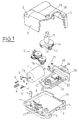
- an exploded perspective view of a first embodiment of an actuator,
- Figure 2:
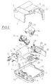
- an exploded perspective view of a second embodiment,
- Figure 3:
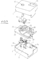
- a third embodiment,
- Figure 4:
- a cross section of a structural detail.
- In Fig. 1, upper and
lower housings holes motor 7 withmounting screws 6, and its foot is inserted into aslit 8 formed in the floor portion of thelower housing 2 to the thereby secured to thelower housing 2. - A worm gear 9 is mounted to a
rotatable shaft 7a of themotor 7, and a supportingplate 11 to be inserted in thelower housing 2 is pressed against the tip of the worm gear 9.
Areduction gear group 12 reduces the rotating speed of themotor 7 for transmission, and is rotatably fitted inshafts 13 vertically provided on thelower housing 2. - At an
output gear 14 which meshes with the final gear of thereduction gear group 12, theoutput shaft 15 is integrally formed so that the rotation of themotor 7 drives theoutput shaft 15 through thereduction gear group 12 for rotation. - The tip of the
output shaft 15 projects outside through ahole 16 drilled in theupper housing 1 to be connected to a link (not shown) in order to drive a body to be driven such as an air conditioning door for an automobile. - On the underside of the
output gear 14, there is secured aconductive brush 17, which is rotated around theoutput shaft 15 together therewith.
On awiring board 20, a control circuit to control the operation of themotor 7 is provided. On the surface of thewiring board 20, aconductive pattern 22 formed of highly electrically-conductive metallic plate is formed on a concentric circle to come into contact with the rotatingconductive brush 17. Adiode 23 is connected in the control circuit. In this respect, the shape of theconductive pattern 22 is schematically shown in Fig. 1. - Also, at the center position of the
conductive pattern 22, abearing hole 25 in which the lower end of theoutput shaft 15 is rotatably fitted is formed in thewiring board 20 so that theconductive brush 17 is rotated around thebearing hole 25. - The
wiring board 20 is a plate-shaped body molded using electrically-insulated plastic material, and during molding, theconductive pattern 22 is inserted and integrally molded to thewiring board 20, and thebearing hole 25 is formed by the molding at the same time. - Accordingly, the
conductive pattern 22 and thebearing hole 25 are integrally molded when thewiring board 20 is molded, and theconductive pattern 22 and thebearing hole 25 can be manufactured within a very small range of displacement. - As a result, a variation or a displacement occuring in the contact positional relation between the
conductive brush 17 which is rotated together with theoutput shaft 15 fitted in thebearing hole 25 and theconductive pattern 22 becomes very small, and the rotation and stop of themotor 7 are controlled in accordance with the contact relation between theconductive brush 17 and theconductive pattern 22, thus enabling the accurate control of the stop angle position of theoutput shaft 15. - On the
conductive pattern 22, there are continuously formed connectingterminals 26 for connecting to an external control circuit andpower supply terminals 27 for connecting to apower terminal 7a of themotor 7. Thepower supply terminals 27 are bent after molding. - Connecting
terminals 26 are disposed in aconnector 28 which has been plastic molded integrally with thewiring board 20.
With such a structure, to control the rotation stop position of theoutput shaft 15, the rotation and stop of themotor 7 are controlled in accordance with the contact relation between theconductive brush 17 and theconductive pattern 22.
In this respect, since a conventional circuit can be used for the control circuit to be connected to theconnector 28, the illustration and description thereof is omitted. - The
wiring board 20 and theconnector 28 which are thus integrally formed can be freely replaced in accordance with the specification of an automotive air conditioner for which the motor actuator is used. Therefore, the shape and the like of theconductive pattern 22 vary depending on the type of thewiring board 20, and theconductive brush 17 may be changed accordingly. - Also, depending on the control circuit formed in the
wiring board 20, the number of the connectingterminals 26 within theconnector 28 is various: from 2 pieces to ten pieces, and the shape and the size of theconnector 28 become different respectively. - The
connector 28 is disposed to project outside from thehousings lower housings holes 29 through which theconnector 28 passes. - However, the connector through-
holes 29 are formed to a sufficient size to allow thelargest connector 28 for use with a motor actuator of the present embodiment to pass through. Therefore, even if anywiring board 20 andconnector 28 are used, theconnector 28 can pass through the connector through-holes 29, and therefore there is no need for replacing the upper andlower housings - However, with the above-mentioned size, the size of the connector through-
hole 29 is too large for theconnector 28 is almost all cases, and there will be a gap between theconnector 28 and the connector through-hole 29. - At the rear end portion of the
connector 28, a plate-shapedcover 30 to fill up the gap between theconnector 28 and the connector through-hole 29 is integrally formed with theconnector 28 or the like to project sideways. Thecover 30 is disposed so that its outer edge portion adheres closely to the inner surface side of the bothhousings connector 28 and the connector through-hole 29. - Fig. 2 illustrates a second embodiment according to the present invention, in which the
wiring board 20 is formed of the so-called printed board, and is separated from theconnector 28 and the like. In this case, therminals 31 formed in thewiring board 20 andterminals 32 projectingly provided on the rear surface of theconnector 28 are connected together by soldering, and thewiring board 20 and theconnector 28 can be replaced as a unit. - Since other portions are the same as in the first embodiment as previously described, like reference numerals or symbols are attached to like portions and the explanation will be omitted.
- According to a motor actuator of the present invention, by replacing only the electric circuit and the connector, it is possible to cope with various different specifications, particularly to share a housing even if the specification of the motor actuator is different. Therefore, there is no need for preparing any plastic molding die for the housing for each specification, thus greatly reducing the manufacturing cost.
- Fig. 3 shows a third embodiment according to the present invention, in which the
connector 28 is formed on the upper surface side of theupper housing 1, and the connectingterminals 26 are bent upward after molding to be positioned within theconnector 28. - Therefore, in the present embodiment, the
wiring board 20 is individually formed separately from theconnector 28, and if the shape of theconnector 28 is changed, it is necessary to change theupper housing 1.
Also, on a stagedportion 2a formed on the upper end edge of thelower housing 2, thewiring board 20 is placed, and themotor 7 and thereduction gear group 12 are disposed under thewiring board 20. - As shown in Fig. 4 a
shaft 13 for supportinggear 10 of thereduction gear group 12 is integrally and vertically provided on thelower housing 2, and its upper end engages with areceiver 33 formed in the underside of thewiring board 20. - Since other portions are basically the same as in the first embodiment as previously described, like reference numerals or symbols are attached to like portions and the explanation will be omitted.
Claims (25)
- Method for manufacturing a wiring board (20) for a motor-driven actuator, particularly for positioning a fluid-flow control member of an automobile air conditioning - and/or heating - and/or ventilating system, the acuator comprising an output shaft (15) rotatably driven by a motor (7), a conductive brush (17) secured to the output shaft (15), the wiring board (20) being provided with a conductive pattern (22) cooperating with the conductive brush (17) in order to control the rotation and stop of the motor (7) and the stop angle position of the output shaft (15), the wiring board (20) containing at least one bearing hole (25) for the output shaft (15),
characterised in that
the relative positions of the bearing hole (25) and the conductive pattern (22) of the wiring board (20) are mutually aligned by integrally molding the bearing hole (25) and the conductive pattern (22) in the wiring board (20). - Method as in claim 1, characterised in that the conductive pattern (22) and the bearing hole (25) are integrally molded into the wiring board (20) when the wiring board is molded.
- Method according to at least one of claims 1 and 2, characterised in that the wiring board (20) is molded as a plate-shaped body of electrically insulating plastic material, that the conductive pattern (22) is inserted into the body, and that the bearing hole (25) is integrally molded into said body, preferably simultaneously, when the conductive pattern (22) is inserted into said body.
- Method according to at least one of claims 1 to 3, characterised in that the conductive pattern (22) is composed of a highly electrically conductive metallic plate, that the metallic plate is inserted into the plate-shaped body or embedded into the plastic material in order to be integrally molded with the wiring board (20) when molding said plate-shaped body, and that the bearing hole (25) is integrally molded into said body at the same time.
- Method according to at least one of claims 1 to 4 characterised in that the output shaft (15) is rotatably fitted into the bearing hole (25) by matching the diameter of the bearing hole (25) to the outer diameter of the output shaft (15).
- Method according to at least one of claims 1 to 5, characterised in that a surface irregularity (9) is integrally molded on at least one surface of the plate-shaped body, preferably when the bearing hole (25) and the conductive pattern (22) are integrally molded in the body.
- A motor-driven actuator, particularly for positioning a fluid-flow control member of an automobile air conditioning - and/or heating - and/or ventilating system, comprising an output shaft (15) rotatably driven by a motor (7), a conductive brush (17) secured to the output shaft (15), and a wiring board (20) being provided with a conductive pattern (22) for cooperation with the conductive brush (17) to control the rotation and stop of the motor (7) and the stop angle position of the output shaft (15), the wiring board (20) further being formed with at least one bearing hole (25) for the output shaft (15),
characterised in that
the bearing hole (25) and the conductive pattern (22) are integrally and simultaneously molded in a plate-shaped body of insulating plastic material with mutually aligned relative positions. - Actuator according to claim 7, characterised in that the conductive pattern (22) is a highly electrically conductive metallic plate with a plurality of concentric circular conductors, that the metallic plate is inserted into the plate-shaped body by integrally molding it with the bearing hole (25) into the plate-shaped body in order to position the conductors in coaxial relationship with the bearing hole (25).
- Actuator according to at least one of claims 7 and 8, characterised in that at least one surface irregularity (33) is molded on at least one surface of the plate-shaped body, the surface irregularity (33) being shaped as a receiving socket for a structural axis (13) for a gear (10) belonging to a reduction gear mechanism (12) interconnecting the motor (7) and the output shaft (15).
- A motor-driven actuator, particularly for positioning a fluid flow control member of an automobile air conditioning - and/or heating - and/or ventilating system, the actuator comprising
a motor (7) for rotating and stopping an output shaft (15) in predetermined angular positions, preferably via a reduction gear mechanism (12), further comprising an electric circuit, preferably containing a conductive pattern (22) on a wiring board (20), to control the operation of the motor (7), at least one connector (28) connecting the electric circuit to an external circuit, and a housing for receiving the motor (7), the reduction gear mechanism (12) and the electric circuit,
characterised in that
at least the connector (28) is replaceably received in the housing (1,2), that a wall portion of the housing (1,2) is provided with a connector passing opening shaped as a connector through hole (29) with a sufficiently large size to allow the largest sized connector (28) among a series of connectors differently sized in accordance with the type of the internal electric circuit to pass through, so that the connector (28) projects from the housing (1,2) for disposition, and that a cover (10) is provided projecting sidewards from the connector (28) for filling a gap between the through hole (29) and the connector (28). - Actuator according to claim 10, characterised in that the housing (1,2) consists of two housing parts having mutually inter-engaging wall portions, and that connector through holes (29) are provided in the mutually inter-engaging housing part wall portions to commonly define the connector passing opening.
- Actuator according to claims 10 and 11, characterised in that the gap between the connector (28) and the passing opening is filled from the inner side of the housing (1,2) by means of the cover (30) adhering with its outer edge portion closely to the inner surface of the housing (1,2).
- Actuator according to at least one of claims 10 to 12, characterised in that the cover (30) is a collar-like plate integrally formed with the connector (28) so that it extends in lateral direction from the connector (28) and projects beyond the periphery of the connector (28).
- Actuator according to claims 10 to 13, characterised in that the electric circuit, namely the wiring board (20), is exchangeably received in the housing (1,2).
- Actuator according to claims 10 to 14, characterised by injection molded plastic housing parts.
- Actuator according to claims 10 to 14, characterised in that the wiring board (20) is molded integrally with the connector (28), and preferably with the cover (30), from plastic material, the wiring board (20) being provided with a plurality of conductors and the connector (28) containing a plurality of conductive terminals (26).
- Actuator according to claims 10 to 14, characterised in that the wiring board (20) is a printed conductor board with accessible terminals (30), that the connector (28) is provided on its rear surface with projecting terminals (32) and that the terminals (30,32) are inter-connected, e.g. by soldering, to create a replaceable wiring board/connector unit.
- Actuator according to claims 16 and 17, characterised in that the wiring board (20) is provided with additional power supply terminals (27) for connection with power terminals (7a,7b) of the motor (7).
- A motor-driven actuator, particularly for positioning a fluid-flow control member in an automobile air conditioning - and/or heating - and/or ventilating system, the actuator comprising a motor (7) for rotating and stopping an output shaft (15), preferably via a reduction gear mechanism (12), further comprising an electric circuit, preferably containing a conductive pattern (22) on a wiring board (20), to control the operation of the motor (7), at least one connector (28) connecting the circuit to an external circuit, and further comprising a housing consisting of an upper and a lower housing part (1,2) for receiving the motor (7), the reduction gear mechanism (12) and the electric circuit,
characterised in that
the connector (28) is structurally provided in one of the housing parts (1,2), that the wiring board (20) is individually formed separately from the connector (28), and that connecting terminals (26) of the wiring board (20) which is received on the lower housing part (2) are positioned within the connector (28). - Actuator according to claim 19, characterised in that the connector (28) is structurally provided, preferably integrally molded, in the upper surface side of the upper housing part (1), and that both housing parts (1,2) are injection molded from plastic material.
- Actuator according to at least one of claims 19 and 20, characterised in that the connector (28) is a connector socket having outer and inner access openings, that the outer access is flush with the upper surface side of the upper housing part (1), and that the connector socket extends inwardly and encircles upwardly bent connecting terminals (26) of the wiring board (20).
- Actuator according to at least one of claims 19 to 21, characterised by a series of upper housing parts (1) differing from another by the shape and/or size of the inbuilt connector (28), and further characterised by one type of a lower housing part (2) compatible with each respective upper housing part (1) of the series to confine the closed housing of the actuator.
- Actuator according to claim 19, characterised in that the lower housing part (2) has a staged portion (2a) on its upper edge for replaceably receiving a selected wiring board (20) of a series of wiring boards differing from each other at least in the number and/or arrangement of the connecting terminals (26).
- Actuator according to at least one of claims 19 to 23, characterised in that the motor (7) and the reduction gear mechanism (12) are mounted into the lower housing parts (2) and below the wiring board (20).
- Actuator according to at least one of claims 19 to 24, characterised in that at least one vertical pin (13) supporting a gear (10) of the reduction gear mechanism (12) is structurally integrated, preferably integrally molded, into the lower housing part (2), and that the upper end of the pin (13) engage a receiving socket (33) integrally formed in the lower surface of the wiring board (20) which is positioned in the lower housing part (2) by the engagement of pin (13) and in the staged portion (2a).
Applications Claiming Priority (6)
| Application Number | Priority Date | Filing Date | Title |
|---|---|---|---|
| JP205/92 | 1992-01-06 | ||
| JP20592 | 1992-01-06 | ||
| JP25622792A JPH06113504A (en) | 1992-09-25 | 1992-09-25 | Motor actuator |
| JP256227/92 | 1992-09-25 | ||
| JP258029/92 | 1992-09-28 | ||
| JP4258029A JP2977388B2 (en) | 1992-01-06 | 1992-09-28 | Motor actuator |
Publications (3)
| Publication Number | Publication Date |
|---|---|
| EP0551113A2 true EP0551113A2 (en) | 1993-07-14 |
| EP0551113A3 EP0551113A3 (en) | 1994-02-09 |
| EP0551113B1 EP0551113B1 (en) | 1996-09-11 |
Family
ID=27274346
Family Applications (1)
| Application Number | Title | Priority Date | Filing Date |
|---|---|---|---|
| EP93100162A Expired - Lifetime EP0551113B1 (en) | 1992-01-06 | 1993-01-07 | Method to manufacture a wiring board for a motor-driven actuator, and motor-driven actuator |
Country Status (3)
| Country | Link |
|---|---|
| EP (1) | EP0551113B1 (en) |
| DE (1) | DE69304552T2 (en) |
| ES (1) | ES2094941T3 (en) |
Cited By (13)
| Publication number | Priority date | Publication date | Assignee | Title |
|---|---|---|---|---|
| EP0639884A1 (en) * | 1993-08-17 | 1995-02-22 | Bayerische Motoren Werke Aktiengesellschaft | Electrical control unit |
| EP0681359A1 (en) * | 1994-05-05 | 1995-11-08 | BITRON S.p.A. | An electromechanical actuator having a supporting and containing housing |
| FR2750542A1 (en) * | 1996-06-27 | 1998-01-02 | Ecia Equip Composants Ind Auto | ELECTRICAL CONNECTION DEVICE FOR DIRECT CURRENT MOTOR |
| WO2000049634A1 (en) * | 1999-02-20 | 2000-08-24 | Robert Bosch Gmbh | Circuit module and control motor with circuit module |
| EP1130742A1 (en) * | 2000-03-03 | 2001-09-05 | Molon Motor & Coil Corporation | Miniaturized motor with gearbox |
| EP1168579A1 (en) * | 2000-06-23 | 2002-01-02 | SAIA-Burgess Electronics AG | Electric motor assembly with at least one connector |
| EP1633033A1 (en) * | 2004-09-06 | 2006-03-08 | Delta Electronics, Inc. | Connector module and motor utilizing the same |
| EP1196980A4 (en) * | 1999-05-21 | 2006-03-15 | Molon Motor & Coil Corp | Compact miniature motor |
| US7270577B2 (en) | 2004-08-18 | 2007-09-18 | Delta Electronics, Inc. | Connector module and motor utilizing the same |
| FR2923893A1 (en) * | 2007-11-19 | 2009-05-22 | Fagorbrandt Sas Soc Par Action | Gas burner securing device for e.g. gas cooktop, has electrically conducting element rotatably driven by motor of gas stop valve around rotational axis and contacting with printed-circuit board |
| US8201478B2 (en) | 2009-04-29 | 2012-06-19 | Molon Motor And Coil Corp. | Gear box for ice dispenser |
| CN107528426A (en) * | 2016-06-17 | 2017-12-29 | 美蓓亚三美株式会社 | Rotating device and vehicle equipped with air conditioning system having the rotating device |
| US10190810B2 (en) | 2014-05-28 | 2019-01-29 | Molon Motor & Coil Corporation | Miniaturized motor assembly |
Families Citing this family (1)
| Publication number | Priority date | Publication date | Assignee | Title |
|---|---|---|---|---|
| DE102024209715A1 (en) * | 2024-10-04 | 2026-04-09 | Robert Bosch Gesellschaft mit beschränkter Haftung | Electric motor-gearbox assembly |
Family Cites Families (3)
| Publication number | Priority date | Publication date | Assignee | Title |
|---|---|---|---|---|
| US4795867A (en) * | 1986-01-17 | 1989-01-03 | Diesel Kiki Co., Ltd. | Motor actuator for air conditioning system |
| US4879803A (en) * | 1987-08-14 | 1989-11-14 | Asmo Co., Ltd. | Method for mounting a plurality of brushes |
| GB8821103D0 (en) * | 1988-09-08 | 1988-10-05 | Lucas Ind Plc | Electrical circuit element |
-
1993
- 1993-01-07 EP EP93100162A patent/EP0551113B1/en not_active Expired - Lifetime
- 1993-01-07 ES ES93100162T patent/ES2094941T3/en not_active Expired - Lifetime
- 1993-01-07 DE DE69304552T patent/DE69304552T2/en not_active Expired - Fee Related
Cited By (20)
| Publication number | Priority date | Publication date | Assignee | Title |
|---|---|---|---|---|
| EP0639884A1 (en) * | 1993-08-17 | 1995-02-22 | Bayerische Motoren Werke Aktiengesellschaft | Electrical control unit |
| EP0681359A1 (en) * | 1994-05-05 | 1995-11-08 | BITRON S.p.A. | An electromechanical actuator having a supporting and containing housing |
| FR2750542A1 (en) * | 1996-06-27 | 1998-01-02 | Ecia Equip Composants Ind Auto | ELECTRICAL CONNECTION DEVICE FOR DIRECT CURRENT MOTOR |
| WO2000049634A1 (en) * | 1999-02-20 | 2000-08-24 | Robert Bosch Gmbh | Circuit module and control motor with circuit module |
| US6465915B1 (en) | 1999-05-21 | 2002-10-15 | Molon Motor & Coil Corporation | Miniaturized motor |
| EP1196980A4 (en) * | 1999-05-21 | 2006-03-15 | Molon Motor & Coil Corp | Compact miniature motor |
| EP1130742A1 (en) * | 2000-03-03 | 2001-09-05 | Molon Motor & Coil Corporation | Miniaturized motor with gearbox |
| EP1168579A1 (en) * | 2000-06-23 | 2002-01-02 | SAIA-Burgess Electronics AG | Electric motor assembly with at least one connector |
| US7270577B2 (en) | 2004-08-18 | 2007-09-18 | Delta Electronics, Inc. | Connector module and motor utilizing the same |
| EP1633033A1 (en) * | 2004-09-06 | 2006-03-08 | Delta Electronics, Inc. | Connector module and motor utilizing the same |
| FR2923893A1 (en) * | 2007-11-19 | 2009-05-22 | Fagorbrandt Sas Soc Par Action | Gas burner securing device for e.g. gas cooktop, has electrically conducting element rotatably driven by motor of gas stop valve around rotational axis and contacting with printed-circuit board |
| US8201478B2 (en) | 2009-04-29 | 2012-06-19 | Molon Motor And Coil Corp. | Gear box for ice dispenser |
| US10190810B2 (en) | 2014-05-28 | 2019-01-29 | Molon Motor & Coil Corporation | Miniaturized motor assembly |
| CN107528426A (en) * | 2016-06-17 | 2017-12-29 | 美蓓亚三美株式会社 | Rotating device and vehicle equipped with air conditioning system having the rotating device |
| US10770951B2 (en) | 2016-06-17 | 2020-09-08 | Minebea Mitsumi Inc. | Rotary apparatus and vehicle having air conditioning system including the rotating apparatus |
| CN107528426B (en) * | 2016-06-17 | 2021-07-13 | 美蓓亚三美株式会社 | Rotating device and vehicle equipped with air-conditioning system having the same |
| CN113270975A (en) * | 2016-06-17 | 2021-08-17 | 美蓓亚三美株式会社 | Rotary position sensor, rotary device and vehicle |
| US11689078B2 (en) | 2016-06-17 | 2023-06-27 | Minebea Mitsumi Inc. | Rotary apparatus and vehicle having air conditioning system including the rotating apparatus |
| US12057758B2 (en) | 2016-06-17 | 2024-08-06 | Minebea Mitsumi Inc. | Rotary apparatus and vehicle having air conditioning system including the rotating apparatus |
| CN113270975B (en) * | 2016-06-17 | 2025-01-24 | 美蓓亚三美株式会社 | Rotary position sensor, rotating device, and vehicle |
Also Published As
| Publication number | Publication date |
|---|---|
| EP0551113B1 (en) | 1996-09-11 |
| EP0551113A3 (en) | 1994-02-09 |
| ES2094941T3 (en) | 1997-02-01 |
| DE69304552D1 (en) | 1996-10-17 |
| DE69304552T2 (en) | 1997-01-23 |
Similar Documents
| Publication | Publication Date | Title |
|---|---|---|
| EP0577201B1 (en) | A control interface device for an electric motor and method of manufacturing the same | |
| EP0551113B1 (en) | Method to manufacture a wiring board for a motor-driven actuator, and motor-driven actuator | |
| DE60032682T2 (en) | Air conditioning with an arrangement of an electrical element | |
| US5777410A (en) | Motor actuator and method of making the same | |
| US20150381016A1 (en) | Motor actuator | |
| US20040253849A1 (en) | Electrical connector | |
| JP2842907B2 (en) | Method of manufacturing wiring for motor actuator | |
| JPH06113504A (en) | Motor actuator | |
| US20030048010A1 (en) | Housing for use in a vehicle to accommodate a printed circuit board containing electronic components | |
| US6919221B2 (en) | Electronic module having a plastic housing with conductive tracks and method of its production | |
| EP1271749B1 (en) | Electric motor | |
| US20070202793A1 (en) | Air Discharging Device For Motor Vehicles | |
| US20070082538A1 (en) | Connector for electrically contacting consumers | |
| JP2977388B2 (en) | Motor actuator | |
| JP3961810B2 (en) | External connector, vehicle actuator device, and vehicle air conditioner device | |
| JP3947341B2 (en) | Manufacturing method of motor actuator wiring | |
| EP1323589B1 (en) | Heating or cooling device for a vehicle with flexible flat cable | |
| CN215435910U (en) | Driver of automobile heating ventilation air conditioner | |
| CN212178004U (en) | Control device and electrically operated valve | |
| EP1633033B1 (en) | Connector module and motor utilizing the same | |
| DE102018211393B4 (en) | ELECTRONIC CONTROL UNIT | |
| CN207354761U (en) | The shell of electronic control unit | |
| WO2015032993A1 (en) | Printed circuit board arrangement, method for manufacturing a printed circuit board arrangement and cooling fan module | |
| DE19719192A1 (en) | Setting drive for motor vehicle rear view mirror | |
| JPH03167774A (en) | Connector assembly method for motor actuator |
Legal Events
| Date | Code | Title | Description |
|---|---|---|---|
| PUAI | Public reference made under article 153(3) epc to a published international application that has entered the european phase |
Free format text: ORIGINAL CODE: 0009012 |
|
| AK | Designated contracting states |
Kind code of ref document: A2 Designated state(s): BE DE ES FR GB IT MC NL PT SE |
|
| RHK1 | Main classification (correction) |
Ipc: H01H 11/06 |
|
| 17P | Request for examination filed |
Effective date: 19930913 |
|
| PUAL | Search report despatched |
Free format text: ORIGINAL CODE: 0009013 |
|
| AK | Designated contracting states |
Kind code of ref document: A3 Designated state(s): BE DE ES FR GB IT MC NL PT SE |
|
| 17Q | First examination report despatched |
Effective date: 19950309 |
|
| GRAH | Despatch of communication of intention to grant a patent |
Free format text: ORIGINAL CODE: EPIDOS IGRA |
|
| GRAH | Despatch of communication of intention to grant a patent |
Free format text: ORIGINAL CODE: EPIDOS IGRA |
|
| GRAA | (expected) grant |
Free format text: ORIGINAL CODE: 0009210 |
|
| AK | Designated contracting states |
Kind code of ref document: B1 Designated state(s): BE DE ES FR GB IT MC NL PT SE |
|
| REF | Corresponds to: |
Ref document number: 69304552 Country of ref document: DE Date of ref document: 19961017 |
|
| ITF | It: translation for a ep patent filed | ||
| ET | Fr: translation filed | ||
| REG | Reference to a national code |
Ref country code: PT Ref legal event code: SC4A Free format text: AVAILABILITY OF NATIONAL TRANSLATION Effective date: 19961016 |
|
| REG | Reference to a national code |
Ref country code: ES Ref legal event code: FG2A Ref document number: 2094941 Country of ref document: ES Kind code of ref document: T3 |
|
| PLBE | No opposition filed within time limit |
Free format text: ORIGINAL CODE: 0009261 |
|
| STAA | Information on the status of an ep patent application or granted ep patent |
Free format text: STATUS: NO OPPOSITION FILED WITHIN TIME LIMIT |
|
| PG25 | Lapsed in a contracting state [announced via postgrant information from national office to epo] |
Ref country code: MC Effective date: 19970731 |
|
| 26N | No opposition filed | ||
| PGFP | Annual fee paid to national office [announced via postgrant information from national office to epo] |
Ref country code: PT Payment date: 19980106 Year of fee payment: 6 |
|
| PGFP | Annual fee paid to national office [announced via postgrant information from national office to epo] |
Ref country code: SE Payment date: 19980123 Year of fee payment: 6 Ref country code: BE Payment date: 19980123 Year of fee payment: 6 |
|
| PGFP | Annual fee paid to national office [announced via postgrant information from national office to epo] |
Ref country code: NL Payment date: 19980127 Year of fee payment: 6 |
|
| PG25 | Lapsed in a contracting state [announced via postgrant information from national office to epo] |
Ref country code: SE Free format text: LAPSE BECAUSE OF NON-PAYMENT OF DUE FEES Effective date: 19990108 |
|
| PG25 | Lapsed in a contracting state [announced via postgrant information from national office to epo] |
Ref country code: BE Free format text: LAPSE BECAUSE OF NON-PAYMENT OF DUE FEES Effective date: 19990131 |
|
| BERE | Be: lapsed |
Owner name: S.K.G. ITALIANA S.R.L. Effective date: 19990131 Owner name: TGK CO. LTD Effective date: 19990131 |
|
| PG25 | Lapsed in a contracting state [announced via postgrant information from national office to epo] |
Ref country code: PT Free format text: LAPSE BECAUSE OF NON-PAYMENT OF DUE FEES Effective date: 19990731 |
|
| PG25 | Lapsed in a contracting state [announced via postgrant information from national office to epo] |
Ref country code: NL Free format text: LAPSE BECAUSE OF NON-PAYMENT OF DUE FEES Effective date: 19990801 |
|
| REG | Reference to a national code |
Ref country code: PT Ref legal event code: MM4A Free format text: LAPSE DUE TO NON-PAYMENT OF FEES Effective date: 19990731 |
|
| REG | Reference to a national code |
Ref country code: GB Ref legal event code: IF02 |
|
| PGFP | Annual fee paid to national office [announced via postgrant information from national office to epo] |
Ref country code: IT Payment date: 20060131 Year of fee payment: 14 |
|
| PGFP | Annual fee paid to national office [announced via postgrant information from national office to epo] |
Ref country code: GB Payment date: 20070109 Year of fee payment: 15 |
|
| PGFP | Annual fee paid to national office [announced via postgrant information from national office to epo] |
Ref country code: ES Payment date: 20070115 Year of fee payment: 15 |
|
| PGFP | Annual fee paid to national office [announced via postgrant information from national office to epo] |
Ref country code: DE Payment date: 20070227 Year of fee payment: 15 |
|
| PGFP | Annual fee paid to national office [announced via postgrant information from national office to epo] |
Ref country code: FR Payment date: 20070105 Year of fee payment: 15 |
|
| GBPC | Gb: european patent ceased through non-payment of renewal fee |
Effective date: 20080107 |
|
| PG25 | Lapsed in a contracting state [announced via postgrant information from national office to epo] |
Ref country code: DE Free format text: LAPSE BECAUSE OF NON-PAYMENT OF DUE FEES Effective date: 20080801 |
|
| REG | Reference to a national code |
Ref country code: FR Ref legal event code: ST Effective date: 20081029 |
|
| PG25 | Lapsed in a contracting state [announced via postgrant information from national office to epo] |
Ref country code: GB Free format text: LAPSE BECAUSE OF NON-PAYMENT OF DUE FEES Effective date: 20080107 |
|
| REG | Reference to a national code |
Ref country code: ES Ref legal event code: FD2A Effective date: 20080108 |
|
| PG25 | Lapsed in a contracting state [announced via postgrant information from national office to epo] |
Ref country code: FR Free format text: LAPSE BECAUSE OF NON-PAYMENT OF DUE FEES Effective date: 20080131 |
|
| PG25 | Lapsed in a contracting state [announced via postgrant information from national office to epo] |
Ref country code: ES Free format text: LAPSE BECAUSE OF NON-PAYMENT OF DUE FEES Effective date: 20080108 |
|
| PG25 | Lapsed in a contracting state [announced via postgrant information from national office to epo] |
Ref country code: IT Free format text: LAPSE BECAUSE OF NON-PAYMENT OF DUE FEES Effective date: 20070107 |