EP0551167B1 - Condenseur de vapeur - Google Patents
Condenseur de vapeur Download PDFInfo
- Publication number
- EP0551167B1 EP0551167B1 EP93300001A EP93300001A EP0551167B1 EP 0551167 B1 EP0551167 B1 EP 0551167B1 EP 93300001 A EP93300001 A EP 93300001A EP 93300001 A EP93300001 A EP 93300001A EP 0551167 B1 EP0551167 B1 EP 0551167B1
- Authority
- EP
- European Patent Office
- Prior art keywords
- condenser
- heating control
- control means
- electrically heated
- steam condenser
- Prior art date
- Legal status (The legal status is an assumption and is not a legal conclusion. Google has not performed a legal analysis and makes no representation as to the accuracy of the status listed.)
- Expired - Lifetime
Links
Images



Classifications
-
- F—MECHANICAL ENGINEERING; LIGHTING; HEATING; WEAPONS; BLASTING
- F28—HEAT EXCHANGE IN GENERAL
- F28B—STEAM OR VAPOUR CONDENSERS
- F28B1/00—Condensers in which the steam or vapour is separate from the cooling medium by walls, e.g. surface condenser
- F28B1/06—Condensers in which the steam or vapour is separate from the cooling medium by walls, e.g. surface condenser using air or other gas as the cooling medium
-
- F—MECHANICAL ENGINEERING; LIGHTING; HEATING; WEAPONS; BLASTING
- F28—HEAT EXCHANGE IN GENERAL
- F28B—STEAM OR VAPOUR CONDENSERS
- F28B11/00—Controlling arrangements with features specially adapted for condensers
-
- Y—GENERAL TAGGING OF NEW TECHNOLOGICAL DEVELOPMENTS; GENERAL TAGGING OF CROSS-SECTIONAL TECHNOLOGIES SPANNING OVER SEVERAL SECTIONS OF THE IPC; TECHNICAL SUBJECTS COVERED BY FORMER USPC CROSS-REFERENCE ART COLLECTIONS [XRACs] AND DIGESTS
- Y10—TECHNICAL SUBJECTS COVERED BY FORMER USPC
- Y10S—TECHNICAL SUBJECTS COVERED BY FORMER USPC CROSS-REFERENCE ART COLLECTIONS [XRACs] AND DIGESTS
- Y10S165/00—Heat exchange
- Y10S165/132—Heat exchange with adjustor for heat flow
Definitions
- the invention relates to steam condensers.
- Patent Specification US-A-4,450,899 discloses a method and apparatus for regulating outdoor steam condensers whereby heating control means in the form of roll-shutters are employed outside of and at a distance from the steam condenser communicating with a steam pipeline. Through the implementation motors and the roll-shutters, a recirculation channel is created for heated air leading to condensation conduits and serves to avoid problems in connection with freezing at low outer environment temperatures.
- screening elements such as flaps or louvres which serve both to protect the steam condenser from the outside elements of the environment and as an apparatus for channelling heated air from the steam condenser over portions of the condenser that are subject to freezing.
- a steam condenser having an exposed surface with an upper portion and a lower portion to allow outside air to come into contact with the condenser;
- heating control means can provide heat electrically to the condenser through the use of electrically heated blankets or electrically heated panels.
- the heating control means can be motor activated and rolled up and down along the outside of the steam condenser.
- the operating temperature of the steam condenser can be regulated uniformly by heating the blankets and panels electrically. This prevents any variation in temperature between the numerous heat exchanger bundles. Such variations in temperature can lead to condensate freezing in some of the heat exchanger bundles.
- electrically heated blankets and panels can reduce the amount of time it takes to heat the heat exchanger bundles due to the inherent quickness involved in an electric heating system.
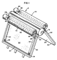
- a vapour or steam condenser has a horizontally positioned cylinder forming an inlet header 16, positioned above the ground and heat exchanger bundles 26 with an appropriate support structure forming a large "A" frame.
- Electrical heating apparatus 2 is provided for upper surface portions of the heat exchanger bundles 26 of the condenser and includes blanket casings 10 in which electrically heated blankets 50 can be stored.
- the blanket casings 10 are attached to, and positioned parallel to the top of the inlet header 16.
- Guide rails 30 are positioned over the heat exchanger bundles 26 and are connected to the inlet header 16 and to the blanket casing 10. Each guide rail 30 runs lengthwise and parallel to the outer edge of the first and last heat exchanger bundle 26 and is supported by a frame base 40.
- Each guide rail 30 is grooved throughout in order to allow guides 36 which anchor and secure the electrically heated blanket 50 to slide uniformly in guide rail grooves 32, shown at Figure 5, as it is moved between a covered and an uncovered position.
- each blanket 50 runs parallel to the frame base 40 and is weighted with a weighty material such as lead in order to keep the electrically heated blanket 50 from separating from the guide rail 30.
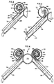
- Figure 5 shows that the blanket casing 10 houses the electrically heated blanket 50 which is driven by a propelling shaft 60 powered by a motor 46.
- the shaft 60 is connected to the motor 46 and extends through the centre of the blanket casing 10 parallel to the blanket casing 10.
- the propelling shaft 60 is encompassed 360° by a spindle 56 and causes the spindle 56 to rotate when driven by the motor 46.
- the spindle 56 serves as an axle on which the electrically heated blanket 50 is spooled and unspooled in order to regulate the exposure and temperature of the heat exchanger bundles.
- the electrically heated blanket 50 is attached to the spindle 56 by a spindle connection 58.
- a blanket casing aperture 28, which is an opening extending the entire length of the blanket casing 10, allows the electrically heated blanket 50 to move from a coiled stored position in the blanket casing 10 along the grooves 32 in the guide rail 30 to an extended position.
- the electrically heated blanket 50 comprises an insulating material capable of holding heat generated from electricity from an electrical source 54 and carried through the motor 46 by means of an electric cable 52.
- the electric cable 52 is located within the propelling shaft 60 and leads into various portions of the electrically heated blanket 50.
- the electrically heated blanket 50 is designed to be unspooled or extended onto an exposed surface of the condenser and, when not in use, spooled into the casing 10.
- Figure 4 shows the spooled or retracted position with all heat exchanger bundles 26 exposed to the environment.
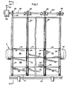
- Figure 6 depicts the steam condenser with the electrical heating apparatus 2 viewed from the top and including the inlet header 16, two of the blanket casings 10, two of the electrically heated blankets 50, the electric cables 52 and the propelling shafts 60.
- Figure 7 shows an alternate embodiment utilizing electrically heated panels 62 instead of the electrically heated blanket 50.
- the electrically heated panels 62 are provided in a plurality of sections and adjacent sections are joined together by panel joints 66. At each panel joint 66 and panel edge 70 of the electrically heated panels 62 are the guides 36 which ride along the grooves 32 set into the guide rail 30.
- the guide rail 30 extends from the frame base 40 upwardly while running parallel to the heat exchanger bundles 26 and extending above the inlet header 16.
- the movement of the electrically heated panels 62 is controlled through the employment of guide wires 34 which are connected to guide wire spools 38 located at the most upward position of the guide rail 30.
- Each guide wire spool 38 encompasses the propelling shaft 60 so that, as the propelling shaft 60 is rotated by the motor 46, each guide wire spool 38 will rotate synchronously with the propelling shaft 60.
- the rotation of the guide wire spools 38 through the propelling shaft 60 enables the guide wires 34 to spool or unspool from the guide wire spools 38 and thus regulate the movement of the electrically heated panels 62.
- Each guide wire 34 is held taut between its connection to the guide wire spool 38 and the guide 36.
- the electrically heated panels 62 can be heated through the use of an electrical charge that is carried from the electrical source 54 through the motor 46 and propelling shaft 60 by the electrical cable 52 that extends to the heating panel edge 70 through the guide rail 30.
- Figures 7 and 9 show the electrically heated panels 62 in the position covering the heat exchanger bundles 26, and Figures 8 and 10 show the electrically heated panels 62 in a stored position thereby exposing the heat exchanger bundles 26.
Landscapes
- Engineering & Computer Science (AREA)
- Mechanical Engineering (AREA)
- General Engineering & Computer Science (AREA)
- Central Heating Systems (AREA)
- General Induction Heating (AREA)
- Control Of Resistance Heating (AREA)
Claims (5)
- Condenseur de vapeur (16, 26) comportant une surface exposée avec une portion supérieure et une portion inférieure pour permettre à l'air extérieur de venir en contact avec le condenseur;des moyens de contrôle de chauffage (50, 62) reliés au condenseur pour réguler la température du condenseur (16, 26);des moyens de fixation (30) reliés au condenseur (16, 26) pour placer les moyens de contrôle de chauffage (50, 62) sur la surface exposée du condenseur dans une position sélectionnée parmi des positions de recouvrement, de non-recouvrement, et de recouvrement partiel; etdes moyens de moteur (46, 60) reliés au condenseur pour déplacer les moyens de contrôle de chauffage (50, 62) entre les positions de recouvrement, de non-recouvrement, et de recouvrement partiel;caractérisé en ce que les moyens de contrôle de chauffage comprennent une pluralité de couvertures chauffées électriquement (50) ou une pluralité de panneaux chauffés électriquement, articulés (62); et en ce quedes moyens électriques (52, 54) sont reliés aux moyens de moteur (46, 60) et aux moyens de contrôle de chauffage (50, 62) pour acheminer un courant électrique jusqu'aux moyens de contrôle de chauffage (50, 62).
- Condenseur de vapeur selon la revendication 1, comprenant des moyens de broche (56) reliés aux moyens de moteur (46, 60) pour étendre et rétracter les moyens de contrôle de chauffage (50, 62).
- Condenseur de vapeur selon la revendication 1, comprenant des moyens de boîtier (10) reliés au condenseur (16, 26) à la portion supérieure de la surface exposée pour loger les moyens de contrôle de chauffage (50, 62).
- Condenseur de vapeur selon la revendication 1, dans lequel les moyens de fixation (30) comprennent un ensemble de gorges (32) et les moyens de contrôle de chauffage (50, 62) sont conduits dans les gorges et sur la surface exposée.
- Condenseur de vapeur selon la revendication 4, dans lequel les moyens de fixation comprennent des moyens de guidage (36) reliés aux extrémités avant des moyens de contrôle de chauffage (50, 62) pour guider les moyens de contrôle de chauffage le long de l'ensemble de gorges (32).
Applications Claiming Priority (2)
| Application Number | Priority Date | Filing Date | Title |
|---|---|---|---|
| US817196 | 1992-01-06 | ||
| US07/817,196 US5159974A (en) | 1992-01-06 | 1992-01-06 | Steam condenser with articulated electrically heated blankets or panels |
Publications (2)
| Publication Number | Publication Date |
|---|---|
| EP0551167A1 EP0551167A1 (fr) | 1993-07-14 |
| EP0551167B1 true EP0551167B1 (fr) | 1996-03-13 |
Family
ID=25222554
Family Applications (1)
| Application Number | Title | Priority Date | Filing Date |
|---|---|---|---|
| EP93300001A Expired - Lifetime EP0551167B1 (fr) | 1992-01-06 | 1993-01-04 | Condenseur de vapeur |
Country Status (4)
| Country | Link |
|---|---|
| US (1) | US5159974A (fr) |
| EP (1) | EP0551167B1 (fr) |
| CA (1) | CA2084981A1 (fr) |
| DE (1) | DE69301737T2 (fr) |
Families Citing this family (5)
| Publication number | Priority date | Publication date | Assignee | Title |
|---|---|---|---|---|
| DE102006029773B3 (de) * | 2006-06-27 | 2007-07-12 | Gea Energietechnik Gmbh | Verfahren zur Errichtung einer Kondensationsanlage |
| GB2471275B (en) * | 2009-06-22 | 2011-12-14 | Gbr Ind Ltd | Air cooler shield system |
| US8302714B2 (en) * | 2010-02-19 | 2012-11-06 | GM Global Technology Operations LLC | Impact and damage resistant front end airflow control device |
| US9447616B2 (en) * | 2013-08-12 | 2016-09-20 | Vinylast, Inc. | Window opening control device |
| US9599363B1 (en) * | 2014-10-20 | 2017-03-21 | NexRev Inc. | Air curtain for an air handler |
Citations (1)
| Publication number | Priority date | Publication date | Assignee | Title |
|---|---|---|---|---|
| US4450899A (en) * | 1980-10-27 | 1984-05-29 | Flakt Aktiebolag | Method of regulating an outdoor steam condensor and apparatus for performing said method |
Family Cites Families (11)
| Publication number | Priority date | Publication date | Assignee | Title |
|---|---|---|---|---|
| US2570376A (en) * | 1950-03-02 | 1951-10-09 | Harvey L Quist | Electrical heating means for silos |
| US2745942A (en) * | 1953-06-18 | 1956-05-15 | Irving M Cohen | Electrically heated mat and the like |
| US3417229A (en) * | 1965-10-14 | 1968-12-17 | Sanders Associates Inc | Electrical resistance heating articles |
| DE1962061C3 (de) * | 1969-12-11 | 1979-05-10 | Kraftwerk Union Ag, 4330 Muelheim | Luftkondensationsanlage |
| US3854459A (en) * | 1973-12-28 | 1974-12-17 | Mack Trucks | Fan shroud for an engine cooling system |
| US4275831A (en) * | 1978-12-26 | 1981-06-30 | Sbs Corporation | Make up air system |
| DE2906394C2 (de) * | 1979-02-20 | 1982-07-22 | Wintershall Ag, 3100 Celle | Luftgekühlte Kondensatoren |
| DE3405107A1 (de) * | 1984-02-14 | 1985-08-22 | Daimler-Benz Ag, 7000 Stuttgart | Abdeckung fuer kuehler von kraftwagen |
| DE3701584C2 (de) * | 1987-01-21 | 1996-02-15 | Bosch Gmbh Robert | Vorrichtung zum Betätigen einer am Kühler eines wassergekühlten Verbrennungsmotors eines Kraftfahrzeuges angeordneten Jalousie |
| IT1215688B (it) * | 1988-01-12 | 1990-02-22 | F B M Hudson Italiana S P A | Procedimento e impianto per protezione contro il congelamento di grandi condensatori di vapord'acqua raffredati con aria. |
| US4909309A (en) * | 1989-04-03 | 1990-03-20 | Energiagazdalkodasi Intezet | Air condenser installation |
-
1992
- 1992-01-06 US US07/817,196 patent/US5159974A/en not_active Expired - Fee Related
- 1992-12-09 CA CA002084981A patent/CA2084981A1/fr not_active Abandoned
-
1993
- 1993-01-04 DE DE69301737T patent/DE69301737T2/de not_active Expired - Fee Related
- 1993-01-04 EP EP93300001A patent/EP0551167B1/fr not_active Expired - Lifetime
Patent Citations (1)
| Publication number | Priority date | Publication date | Assignee | Title |
|---|---|---|---|---|
| US4450899A (en) * | 1980-10-27 | 1984-05-29 | Flakt Aktiebolag | Method of regulating an outdoor steam condensor and apparatus for performing said method |
Also Published As
| Publication number | Publication date |
|---|---|
| DE69301737T2 (de) | 1996-08-08 |
| EP0551167A1 (fr) | 1993-07-14 |
| CA2084981A1 (fr) | 1993-07-07 |
| DE69301737D1 (de) | 1996-04-18 |
| US5159974A (en) | 1992-11-03 |
Similar Documents
| Publication | Publication Date | Title |
|---|---|---|
| JP4279145B2 (ja) | 電流バスを有する風力エネルギープラント | |
| US4949218A (en) | Cabinet with built-in cooling system | |
| US3617691A (en) | Heated snow stopper | |
| US20110217194A1 (en) | Solar-powered soffit fan | |
| EP0551167A1 (fr) | Condenseur de vapeur | |
| CN115811001A (zh) | 一种智能箱式变电站 | |
| CN220754042U (zh) | 一种开关柜体的防雨结构 | |
| US4216369A (en) | Device for cleaning grease-filled cable stub | |
| CN215772356U (zh) | 一种建筑电气用管线装置 | |
| KR200238774Y1 (ko) | 비닐하우스용 내부 보온덮개 자동 개폐시스템 | |
| CN113809658A (zh) | 一种方便进行电气元件检修维护的控制柜 | |
| CN113644710A (zh) | 一种双枪充电机的防护装置 | |
| US1764305A (en) | Transformer cooling system | |
| CN222602178U (zh) | 一种矿用电机的接线装置 | |
| CN218334741U (zh) | 一种户外配电柜 | |
| CN116316378B (zh) | 一种架空输电线路导线防覆冰装置 | |
| US5408051A (en) | Sun shield for aerial cable | |
| CN222107412U (zh) | 一种智能箱式变电站温度调控装置 | |
| US20200395887A1 (en) | Concentrator photovoltaic apparatus | |
| CN219352096U (zh) | 一种电气盒 | |
| CN222379923U (zh) | 一种室内落地式芯光交箱 | |
| WO1999045747A1 (fr) | Radiateur electrique | |
| KR102454952B1 (ko) | 축사 상부 냉각시스템 | |
| CN213995255U (zh) | 一种用于脉冲布袋除尘器的保温箱 | |
| SU737720A1 (ru) | Устройство дл создани воздушнотепловой завесы |
Legal Events
| Date | Code | Title | Description |
|---|---|---|---|
| PUAI | Public reference made under article 153(3) epc to a published international application that has entered the european phase |
Free format text: ORIGINAL CODE: 0009012 |
|
| AK | Designated contracting states |
Kind code of ref document: A1 Designated state(s): DE GB IT |
|
| 17P | Request for examination filed |
Effective date: 19931112 |
|
| 17Q | First examination report despatched |
Effective date: 19940526 |
|
| GRAA | (expected) grant |
Free format text: ORIGINAL CODE: 0009210 |
|
| AK | Designated contracting states |
Kind code of ref document: B1 Designated state(s): DE GB IT |
|
| REF | Corresponds to: |
Ref document number: 69301737 Country of ref document: DE Date of ref document: 19960418 |
|
| ITF | It: translation for a ep patent filed | ||
| PLBE | No opposition filed within time limit |
Free format text: ORIGINAL CODE: 0009261 |
|
| 26N | No opposition filed | ||
| PGFP | Annual fee paid to national office [announced via postgrant information from national office to epo] |
Ref country code: DE Payment date: 19971222 Year of fee payment: 6 |
|
| PGFP | Annual fee paid to national office [announced via postgrant information from national office to epo] |
Ref country code: GB Payment date: 19971223 Year of fee payment: 6 |
|
| PG25 | Lapsed in a contracting state [announced via postgrant information from national office to epo] |
Ref country code: GB Free format text: LAPSE BECAUSE OF NON-PAYMENT OF DUE FEES Effective date: 19990104 |
|
| GBPC | Gb: european patent ceased through non-payment of renewal fee |
Effective date: 19990104 |
|
| PG25 | Lapsed in a contracting state [announced via postgrant information from national office to epo] |
Ref country code: DE Free format text: LAPSE BECAUSE OF NON-PAYMENT OF DUE FEES Effective date: 19991103 |
|
| PG25 | Lapsed in a contracting state [announced via postgrant information from national office to epo] |
Ref country code: IT Free format text: LAPSE BECAUSE OF NON-PAYMENT OF DUE FEES Effective date: 20050104 |