EP0551173A2 - Datenflussrechner - Google Patents
Datenflussrechner Download PDFInfo
- Publication number
- EP0551173A2 EP0551173A2 EP93300024A EP93300024A EP0551173A2 EP 0551173 A2 EP0551173 A2 EP 0551173A2 EP 93300024 A EP93300024 A EP 93300024A EP 93300024 A EP93300024 A EP 93300024A EP 0551173 A2 EP0551173 A2 EP 0551173A2
- Authority
- EP
- European Patent Office
- Prior art keywords
- instruction
- bitstring
- successor
- instructions
- operand
- Prior art date
- Legal status (The legal status is an assumption and is not a legal conclusion. Google has not performed a legal analysis and makes no representation as to the accuracy of the status listed.)
- Withdrawn
Links
Images


Classifications
-
- G—PHYSICS
- G06—COMPUTING OR CALCULATING; COUNTING
- G06F—ELECTRIC DIGITAL DATA PROCESSING
- G06F9/00—Arrangements for program control, e.g. control units
- G06F9/06—Arrangements for program control, e.g. control units using stored programs, i.e. using an internal store of processing equipment to receive or retain programs
- G06F9/30—Arrangements for executing machine instructions, e.g. instruction decode
- G06F9/38—Concurrent instruction execution, e.g. pipeline or look ahead
- G06F9/3802—Instruction prefetching
- G06F9/3804—Instruction prefetching for branches, e.g. hedging, branch folding
-
- G—PHYSICS
- G06—COMPUTING OR CALCULATING; COUNTING
- G06F—ELECTRIC DIGITAL DATA PROCESSING
- G06F11/00—Error detection; Error correction; Monitoring
- G06F11/30—Monitoring
- G06F11/34—Recording or statistical evaluation of computer activity, e.g. of down time, of input/output operation ; Recording or statistical evaluation of user activity, e.g. usability assessment
- G06F11/3466—Performance evaluation by tracing or monitoring
- G06F11/3476—Data logging
-
- G—PHYSICS
- G06—COMPUTING OR CALCULATING; COUNTING
- G06F—ELECTRIC DIGITAL DATA PROCESSING
- G06F9/00—Arrangements for program control, e.g. control units
- G06F9/06—Arrangements for program control, e.g. control units using stored programs, i.e. using an internal store of processing equipment to receive or retain programs
- G06F9/30—Arrangements for executing machine instructions, e.g. instruction decode
- G06F9/38—Concurrent instruction execution, e.g. pipeline or look ahead
- G06F9/3824—Operand accessing
- G06F9/383—Operand prefetching
- G06F9/3832—Value prediction for operands; operand history buffers
-
- G—PHYSICS
- G06—COMPUTING OR CALCULATING; COUNTING
- G06F—ELECTRIC DIGITAL DATA PROCESSING
- G06F9/00—Arrangements for program control, e.g. control units
- G06F9/06—Arrangements for program control, e.g. control units using stored programs, i.e. using an internal store of processing equipment to receive or retain programs
- G06F9/30—Arrangements for executing machine instructions, e.g. instruction decode
- G06F9/38—Concurrent instruction execution, e.g. pipeline or look ahead
- G06F9/3836—Instruction issuing, e.g. dynamic instruction scheduling or out of order instruction execution
- G06F9/3851—Instruction issuing, e.g. dynamic instruction scheduling or out of order instruction execution from multiple instruction streams, e.g. multistreaming
-
- G—PHYSICS
- G06—COMPUTING OR CALCULATING; COUNTING
- G06F—ELECTRIC DIGITAL DATA PROCESSING
- G06F9/00—Arrangements for program control, e.g. control units
- G06F9/06—Arrangements for program control, e.g. control units using stored programs, i.e. using an internal store of processing equipment to receive or retain programs
- G06F9/44—Arrangements for executing specific programs
- G06F9/448—Execution paradigms, e.g. implementations of programming paradigms
- G06F9/4494—Execution paradigms, e.g. implementations of programming paradigms data driven
Definitions
- the present invention relates generally to computers with a dataflow architecture.
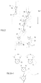
- the dataflow model of computation describes a program by a directed graph, shown in Fig. B-1 to which reference is now made, where nodes 10 - 13 denote instructions of any type, and arcs 14 denote data dependencies.
- the term "instruction” refers to the operation performed at a node.
- the data values A - H are carried as "tokens" along the arcs 14 and a node 10 - 13 can execute whenever its input data, or operands, are available.
- nodes 10 and 11 can execute independently of the other nodes and of each other, node 12 must wait until both of nodes 10 and 11 have executed, and node 13 must wait until node 12 has executed.
- each arc 14 is an unlimited first-in-first-out (FIFO) buffer and each node operates on its operands in a FIFO manner. This, however, is not a practical model. Typically, one or the other or both of the requirements of FIFO operation have to be relaxed.
- FIFO first-in-first-out
- the requirement of FIFO operation at the nodes might be relaxed. If so, then the operands must be "tagged" in some way.
- the operands which are provided to an instruction which executes more than once, such as an instruction within a loop or within a subroutine, must belong to the same iteration number and/or the same invocation of the subroutine.
- the operands are tagged to indicate to which performance, or "instantiation", of the instruction they belong.
- the given instruction being the one about to execute, then has to search among the tokens on its arcs 14 to find two operands with similar tags to serve as its input for the current instantiation.
- FIG. B-2 An example architecture for a dynamic tagged dataflow machine is shown in Fig. B-2. It has an input unit 20, for forwarding, one at a time, operands received either from the outside or from an output unit 22 to a matching store unit 24.
- a tagged operand When a tagged operand enters the matching store 24, its tag is compared to the tags of all the other operands stored therein. If the tag of the entering operand matches a tag of one of the stored operands, then the entering operand and the operand which is matched to it are forwarded to an instruction fetch unit 26 and the matched operand is purged from the matching store 24.
- the entering operand is stored in the matching store 24 to await its matching operand.
- the instruction fetch unit 26 receives the pair of operands and from the information stored in their tags, fetches the instruction to which they belong from a program and data memory 25. The unit 26 then queues the instruction and its operands for eventual execution by an execution unit 28.
- the execution unit 28 executes the instruction and produces a result.
- the result is combined with an appropriate tag and provided to the output unit 22, for returning the result to the input unit 20 as a newly available operand.
- Fig. B-2 provides instructions to the execution unit 28 whenever the two operands are available for an instruction. Successive executed instructions typically are not related to each other and thus, the output of a first instruction is, in general, not used as an input to a second succeeding instruction.
- a critical path through a program is the longest set of consecutive instructions which cannot be avoided and if we define a data dependence path as a path in which the next instruction depends on the output of the previous instruction, then the executed instructions of prior art dataflow machines do not follow data dependence paths and therefore, do not follow the critical path.
- prior art dataflow machines require mechanisms to tag and store every result produced by the execution unit 28.
- the overhead of this mechanism applied over the entirety of results of a program results in a very slow memory access cycle.
- the dataflow/Von-Neumann hybrids described in the above-mentioned articles use compilers which pre-package the machine code of the program into sequences which can only execute in order.
- the hybrids benefit from this restriction by not having to compute at run-time the address of the next instruction in the sequence, since the compiler has already fixed the only way to go.
- the apriori assumption about the exact sequence of execution also avoids the need to check for availability of operands in some cases because the compiler fixes their time of execution and their location in memory.
- a dataflow machine for generally following data dependent path processes.
- the machine includes apparatus for filling an instruction queue with instructions and at least one corresponding outside operand, wherein the instructions follow a plurality of data dependent path processes, apparatus for indicating to which of the data dependent path processes the instruction belongs, execution apparatus for sequentially applying each instruction in the instruction queue to the at least one outside operand and to an active operand corresponding to the data dependent path process to which the instruction belongs and for producing a result from each instruction and apparatus for storing the result as the active operand for use by the execution apparatus with the next instruction of the data dependent path process.
- corresponding to each instruction is a bit-string indicating whether or not any successor instructions of the instruction are enabled and wherein the apparatus for filling include apparatus for reading the bitstring and for selecting a next instruction on the data dependent path process in accordance with the bitstring.
- the apparatus for filling includes apparatus for selecting a new data dependent path process from a new path process queue when an old data dependent path process no longer has any enabled successor instructions.
- the machine includes apparatus for writing the result to memory for use with instructions on other data dependent path processes as one of the at least one outside operand.
- the machine includes apparatus for placing at least one not selected successor instruction in the new path process queue when the bitstring indicates that more than one successor instruction is enabled.
- the machine includes apparatus for temporarily capturing information associated with a small set of instructions queued for execution by the execution apparatus and queued to be written by the apparatus for storing.
- the apparatus for temporarily capturing include a lookahead history buffer for temporarily storing addresses and lookahead bitstrings corresponding to instructions whose outside operands will become shortly become available and a write result history buffer for temporarily storing addresses and results corresponding to instructions which have recently been executed by the execution apparatus.
- the apparatus for filling accesses the lookahead history buffer to receive the lookahead bitstring.
- corresponding to each instruction is a stored bitstring indicating whether or not any successor instructions of the instruction are enabled and wherein the apparatus for filling include apparatus for reading the stored bitstring, for ORing the lookahead bitstring with the stored bitstring to produce an updated bitstring and for selecting a next instruction on the data dependent path process in accordance with the updated bitstring.
- each instruction is a stored bitstring indicating whether or not any successor instructions of the instruction are enabled and wherein the apparatus for storing accesses the write result history buffer to determine if an outside operand for a successor instruction is available only if the bitstring indicates that the successor instruction is not enabled.
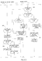
- FIG. 1 and 2 respectively illustrate a simplified block diagram of a dynamically partitioned dataflow machine 50, constructed and operative in accordance with the present invention, and its operation.
- the dataflow machine 50 (Fig. 1) executes data dependent path processes in order to dynamically follow data dependent paths as a program (not shown) executes.
- the direction of the path processes 51 - 53 is dependent on the results of each node and is determined only after the instruction at each node executes. None in the program specifies the direction the path processes 51 - 53 will take upon execution.
- Each node in a path process receives two operands, an "active operand” which is part of the active state of the path process 51, 52 or 53 and an "outside operand" which is received from outside the path process.
- the operand within the active state is transformed with each instruction executed at each node.
- the active operands are shown with solid lines and the outside operands are shown with dotted lines.
- a path process When a path process reaches a node where operands are not available, such as nodes 55 and 68, the machine 50 terminates the relevant path process 51 or 52, respectively. Thus, when the machine 50 arrives at node 55, it terminates the path process 51. Subsequently, the machine 50, executing path process 52, arrives at the same node, now labeled 64. As before, the output of node 54 is available; however, for node 64, the output of node 63, the other operand, is now available and therefore, node 64 is executable.
- the machine 50 continues executing path process 52 from node 64 to node 66 at which it finds that both data-dependent successor nodes, nodes 67 and 70, are executable.
- the machine 50 arbitrarily chooses to continue with node 67 and causes a new path process, path process 53, to be initiated, starting at node 70.
- path process 53 cannot be initiated until node 66 has executed because, until then, the operands for node 70 are not available.
- operands received from outside a given path process can be either data provided from outside the active path processes or, as is more common, they can be the results of nodes of other path processes or earlier nodes of the present path process.
- the result of node 62 is used later as an operand to node 65 of the same path process
- the result of node 63 of path process 52 is used as an operand to node 70 of path process 53.
- the dataflow machine 50 (Fig. 1) of the present invention typically comprises an execution unit 100 for executing the instruction of a current node and for producing a result to be used as the active operand of a selected successor instruction of the current instruction. It also comprises a write result unit 102 for writing a copy of the result to the appropriate location in a memory 104 for use with unselected successor nodes of the current node.
- the write result unit 102 writes the result to memory 104 for future use by the currently unexecutable successor nodes.
- the write result unit 102 writes the result and the instruction of the not-chosen successor node or nodes to a new path process queue 106 for later use in initiating a new path process or processes (e.g. path process 53).
- the new path process queue 106 is a FIFO buffer which accepts instructions and operands which are the first instructions of path processes. It provides one instruction and one operand to a lookahead unit 108 whenever requested to do so by the lookahead unit 108.
- code graph The interconnections of the nodes is called a "code graph” and a section of the graph of a program is called a "code block”.
- code block a section of the graph of a program.
- Each instruction includes in it information regarding the structure of a portion of the code block immediately succeeding the instruction.
- the lookahead unit 108 attempts to pursue a data dependent path through the graph. However, knowing only which instruction follows from a given instruction is insufficient to plan a data dependent path. There needs to be some method of determining which successor nodes are presently executable and which are not.
- each instruction is a successor bitstring containing one bit position for each possible successor instruction.
- a bit position having a value of 1 is called a "set bit”.
- a set bit indicates that the outside operand of the successor instruction is available and therefore, after executing this instruction, the successor instruction can also be executed.
- the lookahead unit 108 utilizes the graph information and the successor bitstring information to determine the executable successor instructions of a current instruction. After selecting one successor instruction, it provides the current instruction and its outside operand to an instruction queue 110, typically comprised of a FIFO buffer, for later execution by the execution unit 100.
- the lookahead unit 108 continues performing the above-described operations for a single path process until it reaches a node for which there currently are no executable successor nodes. At that point, the lookahead unit 108 either, as described in more detail hereinbelow, waits for a more current version of the bitstring of the current instruction or requests the next new path process instruction from the new path process queue 106 and begins the above-described operation on the new path process.
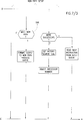
- Figs. 3A - 3D and 4 respectively illustrate four states of a graph of a code block and their corresponding instruction information. Each state occurs after one operation cycle of the machine 50, as is described in more detail hereinbelow.
- a compiler operating on a program written by a user of machine 50, breaks the program into code blocks and, based on the shape of the graph, prepares the instruction information for each instruction in the code block.
- the graphs of Figs. 3A - 3D comprise 9 interconnected nodes, labeled 0 - 8, where nodes 0 and 1 have already executed and their results X and Y are already available to successor nodes 3 and 4. Available operands are noted in Figs. 3A - 3D by solid line arrows and unavailable operands are noted by dashed line arrows.
- Every successor node has two predecessor nodes.
- the first predecessor node is the node which provides the active operand and the second predecessor node is the node which provides the outside operand.
- node 2 is succeeded by nodes 3, 4 and 5 and the second predecessor node of node 4 is node 0. From the point of view of node 0, node 4 is the successor node and node 2 is the second predecessor node.
- Figs. 3A - 3D the instruction performed by each node is noted within the node.
- the instruction at node 3 is multiplication and the instruction at node 4 is division.
- the instructions are listed in Fig. 4 as OP CODES, or operation codes, and they are listed at the number, or address, of each node.
- Fig. 4 Also listed in Fig. 4 are the successor nodes of each node and the second predecessor nodes of the successor nodes.
- the successor node and second predecessor node information form part of an instruction packet for each instruction.
- bitstring corresponding to each node and indicating executable successor nodes is listed as is the operand data which is available at that state.
- a bitstring 200 for node 2 in Fig. 3A is [0 1 1] indicating that successor node 5 is unexecutable but successor nodes 3 and 4 are executable.
- the bitstrings for the other nodes in Fig. 3A have no set bits since none of the operands are available.
- the lookahead unit 108 (Fig. 1) provides the instruction of node 2 to the instruction queue 110.
- the execution unit 100 upon executing the instruction of node 2, produces the result P.
- the lookahead unit 108 selects, in response to reading the bitstring 200, to continue the current path process with node 4.
- the lookahead unit 108 then accesses memory 104 to obtain the instruction packet, bitstring 202 and outside operand Y for the instruction of node 4.
- Memory 104 comprises three sections, an instruction section 120, a bitmap section 122 and a outside operand section 124.
- the three sections 120 - 124 are "congruent" such that an address in a first section located a predetermined number of addresses from the start of the first section corresponds to an address in a second section located the same predetermined number of addresses from the start of the second section.
- an instruction in the fourth location of instruction section 120 is the instruction for node 4 and a bitstring in the fourth location of bitmap section 122 is the bitstring for node 4.
- outside operands are stored in the location in outside operand section 124 corresponding to the instruction whose result they are. Therefore, the outside operand Y, needed for the instruction of node 4 and produced by node 0, is stored at address 0 of outside operand section 124.
- the lookahead unit 108 provides the instruction for node 4 to the instruction queue 110.
- the execution unit 100 produces the result Q.
- bitstring 202 belonging to node 4, is [0 0 0], indicating that there currently are no executable successor nodes. Therefore, the current path process is terminated.
- the write result unit 102 processes those successors of node 2 not on the current path process. For successor node 5, the unit 102 writes the result of node 2, the value P, to location 2 of outside operand section 124.
- the write result unit 102 also updates the bitstrings for the second predecessor nodes of those successor nodes of node 2 which are not executable. Therefore, the write result unit 102, upon processing successor node 5, updates the bitstring 204 of second predecessor node 3.
- a new path process is begun with node 3.
- the lookahead unit 108 provides the instruction of node 3, with the operand values P and X, to the instruction queue 110.
- the execution unit 100 upon executing the instruction of node 3, produces the result R.
- the lookahead unit 108 has to select the next node in the current data dependent path process.
- Fig. 3 there are two possible successor nodes, node 5 whose outside operand was provided by node 2, or node 6 whose outside operand was provided by node 4.
- bitstring 204 of node 3 only indicates that successor node 5 is available.
- the write result unit 102 is about to, but has not yet, updated the bitstring 204 to include the results of cycle 2, the execution of the instruction of node 4. This is known as a "collision", where both the lookahead unit 108 and the write result unit 102 access the same bitstring in the same cycle.
- a write result history buffer 302 (Fig. 5), described in more detail hereinbelow, is maintained and, to increase performance speed a lookahead history buffer 300 is maintained.
- the two buffers both contain information from the last k instructions executed or about to be executed, where k is generally less than or equal to 32.
- the lookahead history buffer 300 is read by the lookahead unit 108.
- Each record of buffer 300 contains an address of an instruction whose outside operand will be made available by the future execution of one of the last k instructions sent to be executed and a bitstring for the instruction contained therein indicating the availability of its outside operand.
- the lookahead history buffer 300 enables the lookahead unit 108 to avoid terminating a path process earlier than necessary.
- the write result history buffer 302 is read by the write result unit 102. Each record of buffer 302 contains the address of an executed instruction and its result.
- the buffer 302 enables the write result unit 102 to avoid collisions.
- lookahead history buffer 300 is larger than the write result history buffer 302.
- the address of node 3 is sent to the lookahead history buffer 300 with the bitstring [0 1 0].
- the execution unit 100 writes the address of node 4 with the result Q.
- the result Q is later written, by write result unit 102, to location 4 of outside operand section 124.
- the lookahead unit 108 accesses buffer 300 to determine if there are any successor instructions which have recently executed and whose results might not have been reflected in the bitstring stored in bitmap section 124 of memory 104.
- bitstring from the history buffer 300 is utilized instead of the bitstring stored in memory 104.
- the lookahead unit 108 looks and finds in the lookahead history buffer 300 the address of node 3 with the bitstring [0 1 0] indicating that the second successor node, node 6, is available. Node 6 is selected as the successor instruction of the path process.
- the write result unit 102 upon later processing node 5 as a successor node of node 3, places the instruction, updated bitstring and operands of node 5 on the new path process instruction queue 106.
- the machine 50 comprises a plurality of new path process instruction queues 106, lookahead units 108 and instruction queues 110, each executing a different path process.
- Four of each of elements 106 - 110 are shown in Fig. 5.
- the queues 106 and 110 are typically formed of FIFO buffers.
- Each lookahead unit 108 follows a single path process from beginning to end. The operation of the lookahead units 108 is described in more detail hereinbelow.
- Two fetch units 304 comprised of combinational logic, arbitrate among the instruction queues 110 to select an instruction to be executed by the execution unit 100.
- one fetch unit 304 is active at a time, taking instructions from whichever of the two instruction queues 110 which feed it is available using a suitable arbitration policy.
- Control is given to the other fetch unit 304 only when the active queue reaches a resting state. The changing of control is noted in Fig. 5 by "miss" signals sent between the fetch units 304.
- the active fetch unit 304 also updates the lookahead history buffer 300 with information from the selected instruction. For each second predecessor instruction of the selected instruction, the active fetch unit 304 places a packet comprising two pieces of information at the top of the queue in buffer 300, 1) its address and 2) a bitstring for the second predecessor instruction having a set bit in the appropriate location corresponding to the currently selected instruction.
- Buffers 300 and 302 are FIFO buffers and therefore, for each packet placed into them, the oldest packet is removed.
- History buffer 300 has one write port, for writing by the active fetch unit 304, and three read ports, for reading by the lookahead units 108, as described in more detail hereinbelow. The ports are simultaneously accessible.
- the packets in the lookahead history buffer 300 are accessible to the lookahead unit 108, as described in more detail hereinbelow and as noted by the arrows labeled 305.
- the selected instruction is provided to the execution unit 100, comprised of an Arithmetic Logic Unit (ALU) 308 and path process registers 310 storing the active operand of each path process.
- ALU Arithmetic Logic Unit
- path process registers 310 storing the active operand of each path process.
- Each instruction, labeled 306, is comprised of the following components, detailed in Fig. 5:
- the ALU 308 uses the path process number to determine the location in the path process register 310 where the active operand for the corresponding path process is stored. If the a flag indicates that the value of the outside operand is in buffer 302, the ALU 308 retrieves the outside operand from the write result history buffer 302. The ALU 308 then applies the operation indicated by the OP CODE to the active operand retrieved from the path process register 310 and to the outside operand either retrieved from the history buffer 302 or received with the instruction 306.
- the ALU 308 uses the path process number to write the result of the operation, or "the executed instruction", into the appropriate location in the path process register 310.
- the ALU 308 also writes the result and the address of the executed instruction to write result history buffer 302.
- the result and elements d - i of the instruction 306 form a result packet which, as shown in Fig. 5, is provided to one of a plurality of write result queues 312, formed of FIFO buffers, each providing a result packet to a write result unit 102.
- the write result unit 102 processes the result packet in order to process those successor instructions not selected as continuing the path process. For each successor instruction, the write result units 102 either write the result to the appropriate location in the outside operand section 124 and update the bitstring of the second predecessor instruction or provide the successor instruction, its outside operand, the result and an updated bitstring of the successor instruction as a new path process instruction to the new path process queue 106.
- the execution instruction has at least one second predecessor instruction which executed shortly before the executed instruction, the operation of the write result units 102 regarding the successor instructions of the executed instruction might be incorrect.
- the ALU 308 writes the address and result of any executed instruction into the write result history buffer 302. If a successor instruction has no set bit, before processing it, the write result units 102 access the write result history buffer 302 to determine if a outside operand of the successor instruction is currently available, even though the bitstring of the executed instruction indicates that the outside operand is not available.
- Buffer 302 operates as follows: the write result units 102 provide buffer 302 with the address of the second predecessor instruction of the successor instruction and the buffer 302 compares the address provided to it with the addresses stored within it.
- buffer 302 has four simultaneously accessible ports. One for writing by the ALU 308, and three for reading.
- the ALU 308 uses one read port and the two write result units 102 use the other two read ports.
- the write result units 102 read from and write to sections 122 and 124 of the memory 104 via an arbiter 314.
- the arbiter 314 arbitrates between memory access requests of the write result units 102 and those of the lookahead unit 108.
- the memory 104 typically is comprised of high speed four port Random Access Memories (RAMs), such as the IDT 7052S or IDT 7052L manufactured by Integrated Device Technology, Inc. of the U.S.A. Two of the ports are for writing by the two write result units 102 and two of the ports are for reading by any two of the four lookahead units 108.
- RAMs Random Access Memories
- Each lookahead unit 108 receives with a new path process instruction the instruction packet, the active and outside operands and the bitstring for the instruction. If the bitstring for the instruction is not up-to-date, the lookahead unit 108 reads bitmap section 122 for the latest version of the bitstring. The lookahead unit 108 then continues operation as for an instruction in the path process.
- the lookahead unit 108 For an instruction in the path process, the lookahead unit 108 provides the lookahead history buffer 300 with the address of the current instruction to determine if any of the successors of the instruction have recently been sent to the ALU 308. If so, the buffer 300 provides the lookahead unit 108 with the first instance of a bitstring for the current instruction.
- the lookahead unit 108 accesses the memory 104, via arbiter 314, to read the bitstring of the current instruction.
- the two bitstrings are OR'd together to provide the latest version of the bitstring of the current instruction.
- the lookahead unit 108 selects a successor instruction, provides the current instruction to the instruction queue 110 and then accesses the memory 104 for the instruction, bitstring and outside operand of the successor instruction and, in parallel, accesses the history buffer 300 for the bitstring, if it exists, of the successor instruction. The process described hereinabove is repeated for each successor instruction.
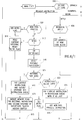
- Fig. 6 and Annex A respectively are a state diagram of the operations of the lookahead unit 108 and pseudocode describing the state diagram for describing, in detail, the operation of each lookahead unit 108.
- the lookahead unit 108 attempts, on every clock cycle, to add one executable instruction to the instruction queue 110. This is not possible with all instructions, as will be described hereinbelow.
- the lookahead unit 108 operates as follows:
- the lookahead unit 108 When processing an instruction, the lookahead unit 108 first decodes, in state 900, the operation code (OP CODE) of the instruction. For regular instructions, the lookahead unit 108 proceeds to state 902. The operations for regular instructions are detailed in sections 1.1.1, 1.2, 1.3 and 1.4 of Annex A.
- the lookahead unit 108 proceeds to state 904.
- the BRANCH instruction operations are detailed in section 1.1.5 of Annex A.
- a BEGIN instruction beginning at state 908, generally immediately follows an APPLY instruction.
- the BEGIN instruction allocates memory space for the bitmap section 122 and outside operand section 124 of the new code block called by the APPLY instruction.
- the BEGIN instruction is detailed in sections 1.1.3 and 3.
- the TERMINATE instruction beginning at state 910, returns to the location from which the BRANCH instruction jumped.
- the TERMINATE instruction is detailed in sections 1.1.4 and 2 of Annex A.
- the lookahead unit 108 first checks (in state 902) that the instruction is a new path process instruction. The unit 108 then checks that the bitstring of the new path is up-to-date. If not, unit 108 proceeds to state 914.
- the lookahead unit 108 in state 914, reads the latest written bitstring of the instruction from bitmap section 122. This step is skipped only if the new path process queue is empty and the new path process instruction is received immediately after being written by one of the write result units 102. The instruction is now ready to be processed on the next clock cycle.
- the line 915 indicates a return to the main state at the next clock cycle. In this case, the instruction is the current instruction.
- the lookahead unit 108 OR's the bitstring received from the bitmap section 122 with a history buffer bitstring, if one was received from the lookahead history buffer 300 as described in more detail hereinbelow. This provides the lookahead unit 108 with a completely up-to-date bitstring.
- the lookahead unit 108 uses the bitstring information to select a successor instruction in state 916.
- the lookahead unit 108 in state 918, puts the current instruction and its outside operand into the instruction queue.
- the lookahead unit 108 obtains from memory 104 the successor instruction and its bitstring and outside operand. In parallel, the unit 108 searches the lookahead history buffer 300 for the first occurrence of the address of the present instruction put there by previously executed second predecessor instructions. This becomes the history buffer bitstring which, as described hereinabove, will, on the next clock, be OR'd with the bitstring received from bitmap section 122. The unit 108 provides these elements as the current instruction information for the next cycle, as indicated by line 915.
- the lookahead unit 108 sets a retry flag to get the latest version of the bitstring of the current instruction on the next instruction and waits until the next clock cycle, processing the present instruction on that cycle. If the second predecessor instruction has executed in the meantime, as will be discovered during the next clock cycle, then the present instruction can, at that time, be sent to the instruction queue 110.
- the lookahead unit 108 terminates the path process, in state 924, by putting the current instruction into the instruction queue 110 and requests, in state 926, a new path process instruction from the new path process instruction queue 106.
- the lookahead unit 108 For the BRANCH instruction (state 904), which branches as a result of a conditional, the lookahead unit 108 sends the BRANCH instruction to the instruction queue 110 and requests a new path process instruction, in state 930, from the new path process instruction queue 106. Since the successor of the BRANCH instruction is not defined until the BRANCH instruction executes, the lookahead unit 108 cannot continue the path process and it therefore terminates the path process and starts a new path process with the next new path process instruction in new path queue 106.
- the APPLY instruction is found at the beginning and end of a called code block. If the APPLY instruction is a beginning APPLY instruction, the unit 108 gets the address of the new code block to be implemented. The address is one of the operands of the APPLY instruction. For ending APPLY instructions, the lookahead unit 108 behaves as if the APPLY instruction is a regular instruction.
- the instruction following the beginning APPLY instruction is the BEGIN instruction. In one clock it requests memory allocation for the new outside operand section 124 and for the new bitmap section 122. On a second clock, indicated by dotted lines, the lookahead unit 108 is in a "begin state", waiting for the memory allocation to complete.
- the lookahead unit 108 in state 934, checks that the flags are in the proper state, as set on the previous clock cycle, and if they are, it stores the address from which the APPLY instruction jumped as the DL parameter of the instruction 306 (Fig. 5). In states 936 - 940, the unit 108 selects the first successor instruction of the BEGIN instruction, places the BEGIN instruction on the instruction queue 110 and reads the successor information. The state is returned to the main state and therefore, on the next clock, the path process is continued with regular instructions.
- the lookahead unit 108 In response to the TERMINATE instruction, the lookahead unit 108, in state 910, requests release of the outside operand section 124 and the bitmap section 122 of memory 104. It also obtains the return address to which the code is to be returned.
- the lookahead unit 108 On the next cycle, the lookahead unit 108 is in a "terminate state".
- the lookahead unit 108 in states 942 and 944, reads the information regarding the successor instruction, which is typically an ending APPLY instruction corresponding to the beginning APPLY instruction and having the same successors, and then resets the APPLY instruction indicator, indicating that the program can continue with the successor instructions of the APPLY instruction.
- the lookahead unit 108 Whenever the dataflow machine 50 is turned on, the lookahead unit 108 is in a reset state (not shown in Fig. 6) during which its internal values are set and a fixed location in memory, storing the initial program load instruction, is read. The lookahead unit 108 is then placed into the main state.
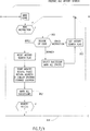
- Fig. 7 and Annex B respectively are a state diagram of the operations of each write unit 102 and pseudocode describing the state diagram for detailing the operation of each write result unit 102.
- Each write result unit 102 is a three stage pipeline.
- the first stage performs preparatory operations and a search of the history buffer
- the second stage accesses memory 104
- the third stage sends an instruction to the new path process queue 106 and prepares for the next cycle of the write result unit 102.
- Each stage operates concurrently with the other stages, each operating on a different successor instruction. When no successors of the current instruction remain to be processed, the next instruction is read into the first stage. However, at the same time, the other stages typically are working on successor instructions of the previous instruction.
- the write result unit 102 begins by determining if the current instruction is new to it. If so, in stage 950, it decodes the OP CODE, performing one set of operations for an APPLY instruction, another for a BRANCH instruction and another for the remaining types of instructions.
- the write result unit 102 begins storing the return address of the function in the address of the APPLY instruction in the outside operand section 124.
- the write result unit 102 marks all of the successors of the APPLY instruction (which are the instructions succeeding the function call) as being unnecessary until after the TERMINATE instruction finishes.
- the write result unit 102 freezes the pipeline for one clock to enable the memory access of this stage to finish.
- the waiting of a clock is indicated in Fig. 7 by the line 954. Otherwise, unit 102 continues, at stage 956, with the history buffer search part of the first stage.
- the new instruction is a BRANCH instruction
- the successor of the BRANCH instruction is selected, based on the result of the branching condition, and the remaining successors are marked as currently not the direction in which processing is continuing.
- the write result unit 102 then continues, at stage 956, with the history buffer search part of the first stage.
- the write result unit 102 effectively goes immediately to the history buffer search part of the first stage. This is shown in Fig. 7 by setting the history buffer search flag, in stage 953, and then checking to see that it is set in stage 956.
- a memory access flag is reset so that the memory access stage will be skipped. Otherwise, the memory access flag is set.
- the instruction comes to the history buffer search section with a selected successor instruction indicated.
- the selected successor instruction is never the instruction succeeding the current instruction along the data dependent path process since the write result unit 102 only processes those successors not chosen to continue the path process.
- the selected successor has a corresponding set bit, as checked in stage 958, there is no need to search the history buffer 302.
- the outside operand of the successor instruction is stored in memory 104 and will be accessed on the next cycle, in the memory access stage.
- the value of a variable op value is set to nil.
- bit corresponding to the selected successor is not set, then a search is performed in the write result history buffer 302 for the address of the second predecessor of the selected successor instruction address. If the address is found, the bit corresponding to the selected successor is set and the value of the result stored with the address is provided and held in the variable op_ value. Assuming that memory access is desired, the instruction proceeds to the memory access stage on the next cycle.
- stage 960 if the bit corresponding to the successor instruction is set, and if the variable op_ value currently has a value of nil, indicating that no search of the history buffer 302 was performed, the outside operand section 124 of memory 104 is accessed. If the history buffer 302 was searched, then there is no need to access memory 104.
- stage 962 the instruction section 120 and the bitmap section 122 of memory 104 are accessed for the successor instruction and its bitstring. Since the successor instruction has a outside operand available, the successor instruction will become a new path process instruction and therefore, will be operated upon in the third stage.
- the result of the current instruction has to be stored until the second predecessor of the selected successor executes. Since there may be many such successor instructions and since the data is written to only one location in outside operand section 124 (the location corresponding to the current instruction), the result is only written for the first such successor instruction.
- bitstring corresponding to the second predecessor instruction is updated, in stage 964, to indicate that the outside operand, of the second predecessor instruction, is available. Since the successor instruction is not executable, a new path process flag is not set.
- stage 966 placing a new path process on the new path process instruction queue 106 and preparing for the next cycle through the three stages. If a new path process instruction is to be prepared, the OP CODE, result, outside operand and current bitstring are provided as a new path process instruction.
- Annex C is a pseudocode describing the operation of the history buffers 300 and 307. It is believed to be self-explanatory.
- Annex D is a specification of an instruction set, including the instructions described hereinabove, useful with dataflow machine 50. It is believed to be self-explanatory.
Landscapes
- Engineering & Computer Science (AREA)
- Theoretical Computer Science (AREA)
- Software Systems (AREA)
- General Engineering & Computer Science (AREA)
- Physics & Mathematics (AREA)
- General Physics & Mathematics (AREA)
- Computer Hardware Design (AREA)
- Quality & Reliability (AREA)
- Multimedia (AREA)
- Advance Control (AREA)
Applications Claiming Priority (2)
| Application Number | Priority Date | Filing Date | Title |
|---|---|---|---|
| IL100598A IL100598A0 (en) | 1992-01-06 | 1992-01-06 | Dataflow computer |
| IL100598 | 1992-01-06 |
Publications (2)
| Publication Number | Publication Date |
|---|---|
| EP0551173A2 true EP0551173A2 (de) | 1993-07-14 |
| EP0551173A3 EP0551173A3 (en) | 1994-09-28 |
Family
ID=11063244
Family Applications (1)
| Application Number | Title | Priority Date | Filing Date |
|---|---|---|---|
| EP9393300024A Withdrawn EP0551173A3 (en) | 1992-01-06 | 1993-01-05 | Dataflow computer |
Country Status (5)
| Country | Link |
|---|---|
| US (1) | US5465372A (de) |
| EP (1) | EP0551173A3 (de) |
| JP (1) | JPH05250499A (de) |
| CA (1) | CA2086722A1 (de) |
| IL (1) | IL100598A0 (de) |
Cited By (1)
| Publication number | Priority date | Publication date | Assignee | Title |
|---|---|---|---|---|
| WO2008116830A3 (en) * | 2007-03-26 | 2009-02-26 | Ericsson Telefon Ab L M | Processor, method and computer program |
Families Citing this family (16)
| Publication number | Priority date | Publication date | Assignee | Title |
|---|---|---|---|---|
| US5640504A (en) * | 1994-01-24 | 1997-06-17 | Advanced Computer Applications, Inc. | Distributed computing network |
| US5941983A (en) * | 1997-06-24 | 1999-08-24 | Hewlett-Packard Company | Out-of-order execution using encoded dependencies between instructions in queues to determine stall values that control issurance of instructions from the queues |
| RU2130198C1 (ru) * | 1997-08-06 | 1999-05-10 | Бурцев Всеволод Сергеевич | Вычислительная машина |
| US6077313A (en) * | 1997-10-22 | 2000-06-20 | Microsoft Corporation | Type partitioned dataflow analyses |
| AU1724899A (en) * | 1997-12-12 | 1999-06-28 | Cacheon, L.L.C. | Naturally parallel computing system and method |
| EP1062577A2 (de) * | 1998-12-08 | 2000-12-27 | Koninklijke Philips Electronics N.V. | Interpretiererprogrammausführungsverfahren |
| US6378066B1 (en) * | 1999-02-04 | 2002-04-23 | Sun Microsystems, Inc. | Method, apparatus, and article of manufacture for developing and executing data flow programs, and optimizing user input specifications |
| US6782469B1 (en) * | 2000-09-29 | 2004-08-24 | Intel Corporation | Runtime critical load/data ordering |
| CN100449478C (zh) * | 2002-05-31 | 2009-01-07 | 德拉华州大学 | 用于实时多线程处理的方法和装置 |
| US7774189B2 (en) * | 2006-12-01 | 2010-08-10 | International Business Machines Corporation | System and method for simulating data flow using dataflow computing system |
| US7860863B2 (en) * | 2007-09-05 | 2010-12-28 | International Business Machines Corporation | Optimization model for processing hierarchical data in stream systems |
| US7941460B2 (en) * | 2007-09-05 | 2011-05-10 | International Business Machines Corporation | Compilation model for processing hierarchical data in stream systems |
| US8161380B2 (en) * | 2008-06-26 | 2012-04-17 | International Business Machines Corporation | Pipeline optimization based on polymorphic schema knowledge |
| US12061954B2 (en) * | 2017-10-27 | 2024-08-13 | Intuit Inc. | Methods, systems, and computer program product for dynamically modifying a dynamic flow of a software application |
| CN111259275B (zh) * | 2018-12-03 | 2023-12-15 | 阿里巴巴集团控股有限公司 | 一种数据追踪方法、设备及存储介质 |
| US12277437B2 (en) * | 2021-12-30 | 2025-04-15 | Atlantic Technical Organization | System and method of path execution optimization |
Family Cites Families (4)
| Publication number | Priority date | Publication date | Assignee | Title |
|---|---|---|---|---|
| JP2564805B2 (ja) * | 1985-08-08 | 1996-12-18 | 日本電気株式会社 | 情報処理装置 |
| US4964042A (en) * | 1988-08-12 | 1990-10-16 | Harris Corporation | Static dataflow computer with a plurality of control structures simultaneously and continuously monitoring first and second communication channels |
| US4972375A (en) * | 1988-08-30 | 1990-11-20 | Fujitsu Limited | Programmable semiconductor memory circuit |
| US5241635A (en) * | 1988-11-18 | 1993-08-31 | Massachusetts Institute Of Technology | Tagged token data processing system with operand matching in activation frames |
-
1992
- 1992-01-06 IL IL100598A patent/IL100598A0/xx unknown
-
1993
- 1993-01-05 CA CA002086722A patent/CA2086722A1/en not_active Abandoned
- 1993-01-05 EP EP9393300024A patent/EP0551173A3/en not_active Withdrawn
- 1993-01-06 JP JP5000850A patent/JPH05250499A/ja active Pending
- 1993-01-06 US US08/000,994 patent/US5465372A/en not_active Expired - Fee Related
Non-Patent Citations (2)
| Title |
|---|
| IEEE TRANSACTIONS ON COMPUTERS vol. 37, no. 5 , May 1988 , NEW YORK US pages 562 - 573 SMITH AND PLESZKUN 'Implementing precise interrupts in pipelined processors' * |
| PROCEEDINGS IFIP 11TH WORLD COMPUTER CONGRESS 28 August 1989 , SAN FRANCISCO, US pages 1155 - 1160 YAMAGUCHI ET AL. 'An architectural design of a highly parallel dataflow machine' * |
Cited By (1)
| Publication number | Priority date | Publication date | Assignee | Title |
|---|---|---|---|---|
| WO2008116830A3 (en) * | 2007-03-26 | 2009-02-26 | Ericsson Telefon Ab L M | Processor, method and computer program |
Also Published As
| Publication number | Publication date |
|---|---|
| US5465372A (en) | 1995-11-07 |
| EP0551173A3 (en) | 1994-09-28 |
| CA2086722A1 (en) | 1993-07-07 |
| IL100598A0 (en) | 1992-09-06 |
| JPH05250499A (ja) | 1993-09-28 |
Similar Documents
| Publication | Publication Date | Title |
|---|---|---|
| US5465372A (en) | Dataflow computer for following data dependent path processes | |
| US5872985A (en) | Switching multi-context processor and method overcoming pipeline vacancies | |
| JP3461704B2 (ja) | 条件コードを使用する命令処理システムおよびコンピュータ | |
| US5499349A (en) | Pipelined processor with fork, join, and start instructions using tokens to indicate the next instruction for each of multiple threads of execution | |
| US5353418A (en) | System storing thread descriptor identifying one of plural threads of computation in storage only when all data for operating on thread is ready and independently of resultant imperative processing of thread | |
| US5150470A (en) | Data processing system with instruction queue having tags indicating outstanding data status | |
| Thistle et al. | A processor architecture for Horizon | |
| US6247124B1 (en) | Branch prediction entry with target line index calculated using relative position of second operation of two step branch operation in a line of instructions | |
| US5197137A (en) | Computer architecture for the concurrent execution of sequential programs | |
| EP0933698B1 (de) | Ermittlung der Latenzzeit eines Rechnerspeichers | |
| EP0565705B1 (de) | Vorrichtung und verfahren zur ausführung von instruktionen in nicht sequentieller reihenfolge | |
| KR920006275B1 (ko) | 데이타 처리 장치 | |
| EP0394624B1 (de) | Mehrfachsequenzprozessorsystem | |
| JPH11212788A (ja) | プロセッサのデータ供給装置 | |
| KR20040017251A (ko) | 다수의 파이프라인을 이용해 패킷을 다수의 프로그래밍엔진에 할당하는 방법 및 프로세서 | |
| AU642927B2 (en) | Minimizing hardware pipeline breaks using software scheduling techniques during compilation | |
| JP2004529405A (ja) | 依存性を決定するためのコンテンツ・アドレス指定可能メモリを実装したスーパースケーラ・プロセッサ | |
| CN1124546C (zh) | 一种超标量处理器及在该超标量处理器中完成指令的方法 | |
| EP0496407A2 (de) | Parallelfliessband-Befehlsverarbeitungssystem für sehr lange Befehlswörter | |
| US7577824B2 (en) | Methods and apparatus for storing expanded width instructions in a VLIW memory for deferred execution | |
| KR100639146B1 (ko) | 카테시안 제어기를 갖는 데이터 처리 시스템 | |
| KR20230124598A (ko) | 높은 처리량 및 낮은 오버헤드 커널 개시를 위한 압축 커맨드 패킷 | |
| JP2003167726A (ja) | コプロセッサ装置およびデータ転送を容易にするための方法 | |
| US7500088B2 (en) | Methods and apparatus for updating of a branch history table | |
| Beckman | Parallel LU decomposition for sparse matrices using quadtrees on a shared-heap multiprocessor |
Legal Events
| Date | Code | Title | Description |
|---|---|---|---|
| PUAI | Public reference made under article 153(3) epc to a published international application that has entered the european phase |
Free format text: ORIGINAL CODE: 0009012 |
|
| AK | Designated contracting states |
Kind code of ref document: A2 Designated state(s): AT BE CH DE DK ES FR GB GR IE IT LI LU MC NL PT SE |
|
| PUAL | Search report despatched |
Free format text: ORIGINAL CODE: 0009013 |
|
| AK | Designated contracting states |
Kind code of ref document: A3 Designated state(s): AT BE CH DE DK ES FR GB GR IE IT LI LU MC NL PT SE |
|
| 17P | Request for examination filed |
Effective date: 19950315 |
|
| 18W | Application withdrawn |
Withdrawal date: 19960506 |