EP0551209A1 - Einlasssystem für Brennkraftmaschinen - Google Patents
Einlasssystem für Brennkraftmaschinen Download PDFInfo
- Publication number
- EP0551209A1 EP0551209A1 EP93300129A EP93300129A EP0551209A1 EP 0551209 A1 EP0551209 A1 EP 0551209A1 EP 93300129 A EP93300129 A EP 93300129A EP 93300129 A EP93300129 A EP 93300129A EP 0551209 A1 EP0551209 A1 EP 0551209A1
- Authority
- EP
- European Patent Office
- Prior art keywords
- inlet
- duct
- drum
- ducts
- supplementary
- Prior art date
- Legal status (The legal status is an assumption and is not a legal conclusion. Google has not performed a legal analysis and makes no representation as to the accuracy of the status listed.)
- Granted
Links
Images


Classifications
-
- F—MECHANICAL ENGINEERING; LIGHTING; HEATING; WEAPONS; BLASTING
- F02—COMBUSTION ENGINES; HOT-GAS OR COMBUSTION-PRODUCT ENGINE PLANTS
- F02B—INTERNAL-COMBUSTION PISTON ENGINES; COMBUSTION ENGINES IN GENERAL
- F02B27/00—Use of kinetic or wave energy of charge in induction systems, or of combustion residues in exhaust systems, for improving quantity of charge or for increasing removal of combustion residues
- F02B27/02—Use of kinetic or wave energy of charge in induction systems, or of combustion residues in exhaust systems, for improving quantity of charge or for increasing removal of combustion residues the systems having variable, i.e. adjustable, cross-sectional areas, chambers of variable volume, or like variable means
- F02B27/0226—Use of kinetic or wave energy of charge in induction systems, or of combustion residues in exhaust systems, for improving quantity of charge or for increasing removal of combustion residues the systems having variable, i.e. adjustable, cross-sectional areas, chambers of variable volume, or like variable means characterised by the means generating the charging effect
- F02B27/0247—Plenum chambers; Resonance chambers or resonance pipes
- F02B27/0257—Rotatable plenum chambers
-
- F—MECHANICAL ENGINEERING; LIGHTING; HEATING; WEAPONS; BLASTING
- F02—COMBUSTION ENGINES; HOT-GAS OR COMBUSTION-PRODUCT ENGINE PLANTS
- F02B—INTERNAL-COMBUSTION PISTON ENGINES; COMBUSTION ENGINES IN GENERAL
- F02B27/00—Use of kinetic or wave energy of charge in induction systems, or of combustion residues in exhaust systems, for improving quantity of charge or for increasing removal of combustion residues
- F02B27/02—Use of kinetic or wave energy of charge in induction systems, or of combustion residues in exhaust systems, for improving quantity of charge or for increasing removal of combustion residues the systems having variable, i.e. adjustable, cross-sectional areas, chambers of variable volume, or like variable means
- F02B27/0205—Use of kinetic or wave energy of charge in induction systems, or of combustion residues in exhaust systems, for improving quantity of charge or for increasing removal of combustion residues the systems having variable, i.e. adjustable, cross-sectional areas, chambers of variable volume, or like variable means characterised by the charging effect
- F02B27/0215—Oscillating pipe charging, i.e. variable intake pipe length charging
-
- F—MECHANICAL ENGINEERING; LIGHTING; HEATING; WEAPONS; BLASTING
- F02—COMBUSTION ENGINES; HOT-GAS OR COMBUSTION-PRODUCT ENGINE PLANTS
- F02B—INTERNAL-COMBUSTION PISTON ENGINES; COMBUSTION ENGINES IN GENERAL
- F02B27/00—Use of kinetic or wave energy of charge in induction systems, or of combustion residues in exhaust systems, for improving quantity of charge or for increasing removal of combustion residues
- F02B27/02—Use of kinetic or wave energy of charge in induction systems, or of combustion residues in exhaust systems, for improving quantity of charge or for increasing removal of combustion residues the systems having variable, i.e. adjustable, cross-sectional areas, chambers of variable volume, or like variable means
- F02B27/0226—Use of kinetic or wave energy of charge in induction systems, or of combustion residues in exhaust systems, for improving quantity of charge or for increasing removal of combustion residues the systems having variable, i.e. adjustable, cross-sectional areas, chambers of variable volume, or like variable means characterised by the means generating the charging effect
- F02B27/0247—Plenum chambers; Resonance chambers or resonance pipes
- F02B27/0263—Plenum chambers; Resonance chambers or resonance pipes the plenum chamber and at least one of the intake ducts having a common wall, and the intake ducts wrap partially around the plenum chamber, i.e. snail-type
-
- F—MECHANICAL ENGINEERING; LIGHTING; HEATING; WEAPONS; BLASTING
- F02—COMBUSTION ENGINES; HOT-GAS OR COMBUSTION-PRODUCT ENGINE PLANTS
- F02B—INTERNAL-COMBUSTION PISTON ENGINES; COMBUSTION ENGINES IN GENERAL
- F02B27/00—Use of kinetic or wave energy of charge in induction systems, or of combustion residues in exhaust systems, for improving quantity of charge or for increasing removal of combustion residues
- F02B27/02—Use of kinetic or wave energy of charge in induction systems, or of combustion residues in exhaust systems, for improving quantity of charge or for increasing removal of combustion residues the systems having variable, i.e. adjustable, cross-sectional areas, chambers of variable volume, or like variable means
- F02B27/0226—Use of kinetic or wave energy of charge in induction systems, or of combustion residues in exhaust systems, for improving quantity of charge or for increasing removal of combustion residues the systems having variable, i.e. adjustable, cross-sectional areas, chambers of variable volume, or like variable means characterised by the means generating the charging effect
- F02B27/0268—Valves
- F02B27/0278—Multi-way valves
-
- F—MECHANICAL ENGINEERING; LIGHTING; HEATING; WEAPONS; BLASTING
- F02—COMBUSTION ENGINES; HOT-GAS OR COMBUSTION-PRODUCT ENGINE PLANTS
- F02B—INTERNAL-COMBUSTION PISTON ENGINES; COMBUSTION ENGINES IN GENERAL
- F02B27/00—Use of kinetic or wave energy of charge in induction systems, or of combustion residues in exhaust systems, for improving quantity of charge or for increasing removal of combustion residues
- F02B27/02—Use of kinetic or wave energy of charge in induction systems, or of combustion residues in exhaust systems, for improving quantity of charge or for increasing removal of combustion residues the systems having variable, i.e. adjustable, cross-sectional areas, chambers of variable volume, or like variable means
- F02B27/0226—Use of kinetic or wave energy of charge in induction systems, or of combustion residues in exhaust systems, for improving quantity of charge or for increasing removal of combustion residues the systems having variable, i.e. adjustable, cross-sectional areas, chambers of variable volume, or like variable means characterised by the means generating the charging effect
- F02B27/0268—Valves
- F02B27/0284—Rotary slide valves
-
- Y—GENERAL TAGGING OF NEW TECHNOLOGICAL DEVELOPMENTS; GENERAL TAGGING OF CROSS-SECTIONAL TECHNOLOGIES SPANNING OVER SEVERAL SECTIONS OF THE IPC; TECHNICAL SUBJECTS COVERED BY FORMER USPC CROSS-REFERENCE ART COLLECTIONS [XRACs] AND DIGESTS
- Y02—TECHNOLOGIES OR APPLICATIONS FOR MITIGATION OR ADAPTATION AGAINST CLIMATE CHANGE
- Y02T—CLIMATE CHANGE MITIGATION TECHNOLOGIES RELATED TO TRANSPORTATION
- Y02T10/00—Road transport of goods or passengers
- Y02T10/10—Internal combustion engine [ICE] based vehicles
- Y02T10/12—Improving ICE efficiencies
Definitions
- the present invention relates to internal combustion engines of reciprocating piston type and more particularly to induction systems for such engines of the type including an air inlet, a first inlet duct communicating with an inlet port into a cylinder of the engine, a supplementary duct and valve means which is movable between a first position in which the air inlet communicates directly with the first inlet duct and a second position in which the air inlet communicates with the first inlet duct via the supplementary duct.
- Engines consume air which is induced through a system of ducts and chambers leading to the intake valves.
- air or an air/fuel mixture
- the output torque produced by the engine at a given speed is dictated largely by the quantity of fuel which can be burned during each combustion stroke and this depends on the mass of air which can be induced into the cylinder. For any given speed it is therefore advantageous to induce the greatest possible mass of air into the cylinder, that is to say, to maximise the volumetric efficiency of the induction process.
- the inlet valve During the induction process of a four stroke engine it is normally arranged for the inlet valve to remain open when the piston reaches the bottom of the inlet stroke. This is because, despite the fact that the piston is no longer moving, air continues to enter the cylinder under the influence of the kinetic energy or momentum of the air travelling through the induction system. The pressure in the cylinder rises due to the increasing mass of air within it until there is no further flow of air into the cylinder. It is normally arranged for the inlet valve to close at or near this point in the cycle. Advantage can, therefore, be taken of the kinetic energy of the air within the induction system to increase the mass of air induced into the cylinder.
- the velocity of the inlet air in the induction system is lower than at high engine speeds. Since the kinetic energy of the air is proportional to the square of the velocity, this causes a reduction in the kinetic energy effect and hence a reduction in volumetric efficiency and in the output torque, at low engine speeds.
- a known solution to this problem is to use a dual area induction system which allows the velocity of the air to be increased at low engine speeds compared with a single area system.
- Such systems typically include two parallel ducts which communicate with the same inlet port, one of which can be selectively blocked by a valve arrangement. At low engine speeds only one of the ducts is open. This increases the velocity, and hence kinetic energy, of the air travelling through the induction system. At high engine speeds the valve opens to allow flow through both ducts so that the induction of air is not restricted.
- GB-A-22219544 on which the precharacterising portion of Claim 1 is based discloses a solution to this problem.
- This specification discloses an induction system including a dual length inlet duct which comprises two portions of which one communicates at one end with the engine and at the other end with a rotary valve which selectively connects it either directly to an inlet air plenum or to one end of the other portion, whose other end communicates with the inlet air plenum.
- the length of the inlet duct is thus selectively variable between two different values and is varied in dependence on the engine speed so that the reflected pressure wave effect may be used at both high and low engine speeds.
- JP 60-142013A A similar induction system is disclosed in JP 60-142013A in which there are two inlet ducts in parallel which communicate with respective inlet ports and with respective supplementary ducts which communicate with a common inlet manifold via respective openings in a rotatable drum. As the drum is rotated the effective length of the supplementary ducts varies whereby the length of the inlet paths into the cylinder is continuously variable.
- One of the inlet ducts includes a butterfly valve which is closed at low engine speeds, so that all the inlet air flows in through the other inlet duct, but is open at high engine speeds.
- an induction system of the type referred to above is characterised in that a second inlet duct is provided which is connected to the same inlet port in parallel with the first inlet duct and that the valve means is so constructed that when it is in the first position the air inlet communicates directly with the first and second inlet ducts and when it is in the second position it communicates only with the first inlet duct and not with the second inlet duct.
- the valve means may occupy first and second positions at high and low engine speeds respectively.
- the air inlet communicates with both the inlet ducts and the inlet air therefore flows to the associated cylinder through a relatively short flow path of relatively large cross-sectional area.
- the inlet does not communicate with the second inlet duct but communicates only with the first inlet duct via the supplementary duct.
- the air flow passage is therefore of lesser cross-section and of greater length than at high engine speeds whereby both the kinetic energy effect and the pressure wave reflection effect may be made use of effectively at both high and low engine speeds.
- the valve means may take a variety of forms but in the preferred embodiment comprises a cylindrical drum in whose wall two or more openings are formed and whose interior communicates with the air inlet, the drum being rotatable about its axis between the second position in which one opening communicates with the supplementary duct and the other opening(s) are blocked and the first position in which two openings communicate with the first and second inlet ducts.
- the supplementary duct may be a wholly separate duct but it is preferred for reasons of simplicity and compactness that it is defined by the outer surface of the drum and the inner surface of a housing containing the drum.
- the drum may be necessary for one or more openings in the drum to be blocked. In one embodiment of the invention this is achieved by rotatably positioning the drum within a fixed cylinder in which three openings are formed which communicate with the first duct, the second duct and the supplementary duct, respectively.
- the first inlet duct is open to the flow of air at all times and is connected to the air inlet either directly or via the supplementary duct, depending on the angular position of the drum.
- the second inlet duct is open to the flow of air only when the drum is in the high engine speed position. In the low engine speed position it is blocked at its upstream end by the drum. This normally means that the downstream end of the second duct is open to the flow of air through the first inlet duct. This may constitute a problem since the second inlet duct may act as a dead volume damping out or reflecting pressure waves. It may therefore also be desirable to block the downstream end of the second duct when the valve is in the low engine speed position.
- valve means situated at the downstream end of the second duct and by connecting means which connect the two valve means together and are so arranged that the valve means in the second duct moves between the open and closed positions as the drum moves between the first and second positions.
- the induction system has an inlet air pathway of two different lengths and two different areas.
- the valve means includes a cylindrical drum having inner and outer walls which together define the supplementary duct and in which a plurality of openings is formed and that the drum is rotatable between first, second and third positions in which the air inlet communicates with the first inlet duct only via the supplementary duct, with the first and second inlet ducts only via a portion of the supplementary duct and with the first, second and third inlet ducts, respectively.
- the present invention also embraces a reciprocating internal combustion engine including an induction system of the type referred to above. If the engine includes a plurality of cylinders it will include a plurality of such induction systems. Whilst the drums of the various induction systems may be separate and actuated separately, it is preferred that they are connected together to form an integral unit.
- Such an engine will include an inlet valve associated with each cylinder and cooperating with an inlet port formed in a cylinder head and it is preferred that the first and second ducts are within a common pipe and are separated by a common partition wall.
- the partition wall may extend beyond the common pipe into the inlet port or alternatively, particularly in the case in which a valve is provided at the downstream end of the second inlet duct, it may terminate at the junction of the cylinder head with the common pipe.
- the induction systems described above are ideally suited to in-line engines, that is to say engines including a plurality of cylinders arranged in a single line, where all the first and second inlet ducts are connected to the same side of the drum. If the engine is of "V" type with the cylinders arranged in two rows, it is desirable for the induction systems to be positioned between the two rows of cylinders and in this event the first and second ducts for the two rows of cylinders are ideally connected to opposite sides of the drums.
- each cylinder is connected to an induction system in which the drum is rotatably received within a fixed cylinder in which three openings are formed which communicate with the first duct, the second duct and the supplementary duct, respectively and if the drums associated with one row of cylinders have two openings formed in them and the drums associated with the other row of cylinders have three openings formed in them, all the drums being connected together to form an integral unit.
- rotation of the integral drum unit in one direction or the other will result in all the induction systems moving simultaneously between the low speed and high speed positions notwithstanding the fact that the first and second ducts associated with the two different rows of cylinders communicate with their respective drum on opposite sides.
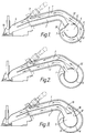
- Figures 1 and 2 show an induction system for a single cylinder engine or one cylinder of a multiple cylinder engine. In the event that the engine has more than one cylinder, similar induction systems will be associated with each of them.
- the induction system comprises a first inlet duct 1 and a second inlet duct 2 which are separated from one another by a dividing wall 3 and which preferably extend into the inlet port 4 of the associated cylinder, that is to say into the region within the cylinder head directly upstream of the associated inlet valve 10.
- a fuel injector 11 is arranged to inject fuel into, or shortly upstream of, the inlet port 4.
- a rotatable drum 6 which constitutes a valve in the nature of a rotary gate valve and which defines a chamber 5 which is in communication with or constitutes part of the air inlet pipe or manifold.
- a supplementary duct 8 Extending around a major proportion of the circumference of the drum 6 is a supplementary duct 8 whose outer surface is defined by a casing 9.
- the duct 8 At one end, seen on the left in Figures 1 and 2, the duct 8 is closed by a transverse wall 30 and at its other end it merges into the inlet duct 1.
- the drum is movable between a low speed position, seen in Figure 1, in which the aperture 12 is blocked by a wall or baffle 32, which is connected to or forms part of the partition wall 3, and the aperture 7 communicates with the closed end of the supplementary duct 8, and a high speed position, seen in Figure 2, in which the apertures 7 and 12 communicate with the inlet ducts 2 and 1, respectively.
- a low speed position seen in Figure 1
- the aperture 12 is blocked by a wall or baffle 32, which is connected to or forms part of the partition wall 3
- the aperture 7 communicates with the closed end of the supplementary duct 8
- a high speed position seen in which the apertures 7 and 12 communicate with the inlet ducts 2 and 1, respectively.
- the inlet air all flows through the relatively long and narrow passage constituted by the ducts 1 and 8.
- the inlet air flows through the relatively shorter and wider passage constituted by the two parallel ducts 1 and 2.
- the cross-sectional area and length of the passage are selected so as to utilise both the
- Figure 3 shows a further embodiment in which the drum 6 carries a generally tangentially extending flap 18.
- the flap 18 prevents communication of the ducts 1 and 8 and thus prevents any undesired pressure wave effects due to the presence of the duct 8.
- the flap 18 is received in a recess 19 in the wall of the duct 1 so that a smooth wall surface is presented to the air flow.
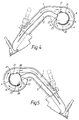
- FIG 4 shows the induction system for one of the left hand row of cylinders which again includes first and second ducts 1 and 2 and a rotatable drum 6.
- the drum 6 is received within a fixed cylinder 20 in whose wall three openings 21, 22 and 23 are formed. Openings 21 and 22 communicate with the first and second ducts 1 and 2, respectively whilst opening 23 communicates with the upstream end of the circumferential duct 8 which in this case is defined by the cylinder 20 and the outer casing 9.
- the drum 6 has two openings 7 and 12, as before. In the low engine speed position shown in Figure 4 opening 7 is aligned with opening 23 and opening 12 is blocked so that all the air flows through the ducts 8 and 1.
- the drum 6 is rotated clockwise into the high engine speed position (not shown) in which openings 12 and 7 are in registry with openings 21 and 22, respectively and the inlet air flows through the two parallel ducts 1 and 2.
- FIG 5 shows the induction system for one of the right hand cylinders of the "V" engine. All the static parts of the system form a mirror image, about a vertical axis, of the static parts shown in Figure 4.
- the drum 6 has three openings 27, 28 and 29. In the low engine speed position, shown in Figure 4, the openings 27 and 28 are blocked and the opening 29 is in registry with the opening 23 in the fixed drum 20 so that the air flows through the ducts 8 and 1.
- the drum 6 again moves in the clockwise direction into the high speed position and in this position the opening 29 is blocked and the openings 27 and 28 are in registry with the openings 21 and 22, respectively, so that the air flows through the ducts 1 and 2.
- the drum 6 moves in the same direction for both the right and left cylinders of the engine they may be constituted by a single drum whereby the sectional views of the drums 6 in Figures 4 and 5 show the same drum but at different points along its length. This results in a considerable economy in manufacturing expense and a reduction in constructional complexity.
- the drums of all the cylinders of the engine it is convenient for the drums of all the cylinders of the engine to be constituted by a single, elongate drum in which the appropriate openings are formed.
- the embodiments described above relate to an induction system with two different areas and two different lengths, but the embodiment shown in Figures 6 to 8, from which the inlet valve and inlet port have been omitted for the sake of clarity, provides three different areas and three different lengths.
- the first and second inlet ducts 1 and 2 there is a third inlet duct 34.
- These inlet ducts communicate with the interior of the casing 9 through respective openings 36,38 and 37.
- the rotatable drum 6 comprises two concentric walls, of which the inner wall 42 has a single opening 7 and the outer wall 40 has an opening 44 generally aligned with the opening 7 and two further openings 46 and 48 spaced about 150° from the opening 44 in opposite directions.
- the space between the two walls 40,42 constitutes the supplementary duct 8.
- Extending from the inner wall 42 from a point adjacent one side of the opening 7 to the outer wall 40 is a flap 50 which substantially blocks the supplementary duct 8 on that side of the opening 7.
- the interior of the drum 6 communicates via the opening 7, supplementary duct 8, which extends right round the drum 6, and opening 36 with the first inlet duct 1.
- the inlet ducts 2 and 34 are closed by the outer wall 40 of the drum 6.
- the air inlet pathway thus has a small cross-sectional area and a substantial length.
- the drum 6 In the mid engine speed range, the drum 6 is moved into the position shown in Figure 7. In this position air flows through the opening 7 and round only a proportion of the length of the supplemental duct 8 and then through the openings 36 and 38 into the inlet ducts 1 and 2.
- the inlet air pathway thus has an increased area and a reduced length.
- the air flows out of the opening 7 and part of it then flows directly through the openings 36 and 38 into the inlet ducts 36 and 38 whilst the remainder of it flows over half the length of the supplementary duct 8 and then through the opening 39 into the inlet duct 34.
- the length of all three routes is substantially the same.
- the inlet air pathway thus has a yet further increased area and reduced length.
- inlet 34 and opening 39 may be omitted to provide an induction system having two different areas but three or more different lengths.
- An engine which incorporates an induction system of the type described above will incorporate an engine speed sensor and an actuator, e.g. as described in GB-A-2221954, connected to the drum 6, which are so arranged that the drum is moved between the high and low speed positions as the engine speed passes through a predetermined threshold value.
- the invention is also applicable to engines using so-called Exhaust Gas Recirculation (EGR) that is to say engines in which, under at least certain load and speed conditions, a proportion of the inlet air is replaced by recycled exhaust gas (REG).
- EGR Exhaust Gas Recirculation
- REG recycled exhaust gas
- FIGS 9A to 9D The crucial portions of the induction system of the two valves of a twin inlet valve engine using EGR are shown in Figures 9A to 9D.
- Each inlet port (which is not shown for the sake of clarity) is again connected to first and second parallel inlet ducts 1 and 2, upstream of which is a rotatable drum 50 received within a further rotatable drum 6. Both drums have openings formed in them but these are different for the two inlet ports.
- a supplementary duct 8 Defined between the outer casing 9 and the outer drum 6 is a supplementary duct 8.
- the inner drum 50 is divided internally into two portions by a partition 52.
- the first portion 54 contains REG and has no aperture formed in it, for reasons which will become clear below.
- the second portion 56 contains air and has a single opening 58 extending over nearly 180° formed in its outer wall.
- the outer drum 6 has two adjacent openings 60 and 61 formed in its outer wall.
- Figures 9A and 9B illustrate the positions of the drums at high engine speed and high and low load, respectively.
- the portion 56 of the drum 50 which contains air communicates in both cases directly with both inlet ducts 1 and 2 through the openings 58, 60 and 61, that is to say not via the supplementary duct, notwithstanding the fact that in Figure 9B the inner drum 50 has rotated through about 45°.
- Figures 9C and 9D illustrate the positions of the drums at low engine speed and high and low load, respectively.
- the portion 56 of the drum 50 communicates in both cases only with one inlet duct 1 and does so via the supplementary duct 8, notwithstanding the fact that in Figure 9D the inner drum has rotated through about 45°, whereby the pathway to the first inlet port is of reduced area and increased length.
- the induction system for the first inlet port thus operates in a manner very similar to that described above in connection with Figures 1 to 5.
- the inner and outer drums are of the same configuration and this is because they are constituted by longitudinally spaced portions of the same components.
- the outer drum 6 has two apertures 62 and 64 formed in it, whilst the inner drum 50 has two apertures 66,68 which communicate with the portion 56 which contains air and a further aperture 70 which communicates with the portion 54 which contains REG.
- the portion 56 containing air communicates directly with the two inlet ducts 1 and 2 and no REG passes into them.
- the portion 56 containing air does not communicate with the inlet ducts and the portion 54 containing REG communicates with one of the inlet ducts via the openings 70 and 62, as shown in Figure 9B.
- the air required for combustion is supplied through the other inlet port.
- the portion 56 containing air communicates with one of the inlet ducts via the supplementary duct 8 and no REG is allowed to enter the inlet port, as shown in Figure 9C.
- the portion 54 containing REG communicates with one of the inlet ducts via the supplementary duct 8 and no air is allowed to enter the inlet port; all the necessary air enters via the other inlet port.
- the two drums are thus moved independently.
- the drum 6 is moved in response to engine speed and for this purpose is provided with a speed sensor and actuator of known type.
- the drum 50 is moved in accordance with engine load and for this purpose is coupled to an actuator connected to a load sensor or e.g. to the engine throttle.
- drums 6 and 50 associated with the two inlet ports are part of the same components. It will be appreciated that in practice, even with a multi-cylinder engine with two inlet ports per cylinder there will be only two drums, each of which is provided with the numerous openings required for the various ports.
Landscapes
- Engineering & Computer Science (AREA)
- Chemical & Material Sciences (AREA)
- Combustion & Propulsion (AREA)
- Mechanical Engineering (AREA)
- General Engineering & Computer Science (AREA)
- Characterised By The Charging Evacuation (AREA)
Applications Claiming Priority (2)
| Application Number | Priority Date | Filing Date | Title |
|---|---|---|---|
| GB9200425 | 1992-01-09 | ||
| GB929200425A GB9200425D0 (en) | 1992-01-09 | 1992-01-09 | Induction systems for internal combustion engines |
Publications (2)
| Publication Number | Publication Date |
|---|---|
| EP0551209A1 true EP0551209A1 (de) | 1993-07-14 |
| EP0551209B1 EP0551209B1 (de) | 1995-10-25 |
Family
ID=10708343
Family Applications (1)
| Application Number | Title | Priority Date | Filing Date |
|---|---|---|---|
| EP93300129A Expired - Lifetime EP0551209B1 (de) | 1992-01-09 | 1993-01-08 | Einlasssystem für Brennkraftmaschinen |
Country Status (3)
| Country | Link |
|---|---|
| EP (1) | EP0551209B1 (de) |
| DE (1) | DE69300677T2 (de) |
| GB (1) | GB9200425D0 (de) |
Cited By (7)
| Publication number | Priority date | Publication date | Assignee | Title |
|---|---|---|---|---|
| WO1995018295A1 (de) * | 1993-12-24 | 1995-07-06 | Audi Ag | Saugrohranlage für eine mehrzylinder-brennkraftmaschine |
| EP0728918A3 (de) * | 1995-02-23 | 1997-07-23 | Mann & Hummel Filter | Ansaugvorrichtung für eine Kolbenbrennkraftmaschine |
| EP0822325A3 (de) * | 1996-08-02 | 1998-05-20 | Audi Ag | Vorrichtung zum Steuern der Ansaugquerschnitte von Verbrennungsluft-Einlassleitungen von Brennkraftmaschinen |
| WO1999024702A1 (de) * | 1997-11-11 | 1999-05-20 | Filterwerk Mann+Hummel Gmbh | Saugrohr mit einlegekomponente |
| WO2000049280A1 (de) * | 1999-02-18 | 2000-08-24 | Filterwerk Mann+Hummel Gmbh | Ansaugvorrichtung |
| WO2006072874A1 (en) * | 2005-01-07 | 2006-07-13 | Toyota Jidosha Kabushiki Kaisha | Intake air device for internal combustion engine |
| CN107246339A (zh) * | 2017-08-14 | 2017-10-13 | 广西玉柴机器股份有限公司 | 发动机进气系统 |
Citations (3)
| Publication number | Priority date | Publication date | Assignee | Title |
|---|---|---|---|---|
| US2835235A (en) * | 1955-06-20 | 1958-05-20 | Daimler Benz Ag | Intake manifold for internal combustion engines |
| US4919086A (en) * | 1989-02-22 | 1990-04-24 | Siemens-Bendix Automotive Electronics Ltd. | Integrated tuned induction system |
| DE4028489A1 (de) * | 1990-09-07 | 1992-03-12 | Opel Adam Ag | Luftangsaugeinrichtung fuer eine brennkraftmaschine |
Family Cites Families (1)
| Publication number | Priority date | Publication date | Assignee | Title |
|---|---|---|---|---|
| DE3446377C2 (de) * | 1983-12-21 | 1994-05-05 | Mazda Motor | Ansaugvorrichtung für eine Kolben-Brennkraftmaschine |
-
1992
- 1992-01-09 GB GB929200425A patent/GB9200425D0/en active Pending
-
1993
- 1993-01-08 EP EP93300129A patent/EP0551209B1/de not_active Expired - Lifetime
- 1993-01-08 DE DE69300677T patent/DE69300677T2/de not_active Expired - Fee Related
Patent Citations (3)
| Publication number | Priority date | Publication date | Assignee | Title |
|---|---|---|---|---|
| US2835235A (en) * | 1955-06-20 | 1958-05-20 | Daimler Benz Ag | Intake manifold for internal combustion engines |
| US4919086A (en) * | 1989-02-22 | 1990-04-24 | Siemens-Bendix Automotive Electronics Ltd. | Integrated tuned induction system |
| DE4028489A1 (de) * | 1990-09-07 | 1992-03-12 | Opel Adam Ag | Luftangsaugeinrichtung fuer eine brennkraftmaschine |
Non-Patent Citations (1)
| Title |
|---|
| PATENT ABSTRACTS OF JAPAN vol. 10, no. 243 (M-536)(2398) 19 November 1986 & JP-A-61 142 326 ( YAMAHA MOTORS CO LTD ) * |
Cited By (8)
| Publication number | Priority date | Publication date | Assignee | Title |
|---|---|---|---|---|
| WO1995018295A1 (de) * | 1993-12-24 | 1995-07-06 | Audi Ag | Saugrohranlage für eine mehrzylinder-brennkraftmaschine |
| CN1059013C (zh) * | 1993-12-24 | 2000-11-29 | 奥迪股份公司 | 多气缸内燃机的吸气管装置 |
| EP0728918A3 (de) * | 1995-02-23 | 1997-07-23 | Mann & Hummel Filter | Ansaugvorrichtung für eine Kolbenbrennkraftmaschine |
| EP0822325A3 (de) * | 1996-08-02 | 1998-05-20 | Audi Ag | Vorrichtung zum Steuern der Ansaugquerschnitte von Verbrennungsluft-Einlassleitungen von Brennkraftmaschinen |
| WO1999024702A1 (de) * | 1997-11-11 | 1999-05-20 | Filterwerk Mann+Hummel Gmbh | Saugrohr mit einlegekomponente |
| WO2000049280A1 (de) * | 1999-02-18 | 2000-08-24 | Filterwerk Mann+Hummel Gmbh | Ansaugvorrichtung |
| WO2006072874A1 (en) * | 2005-01-07 | 2006-07-13 | Toyota Jidosha Kabushiki Kaisha | Intake air device for internal combustion engine |
| CN107246339A (zh) * | 2017-08-14 | 2017-10-13 | 广西玉柴机器股份有限公司 | 发动机进气系统 |
Also Published As
| Publication number | Publication date |
|---|---|
| EP0551209B1 (de) | 1995-10-25 |
| GB9200425D0 (en) | 1992-02-26 |
| DE69300677T2 (de) | 1996-04-11 |
| DE69300677D1 (de) | 1995-11-30 |
Similar Documents
| Publication | Publication Date | Title |
|---|---|---|
| US5852994A (en) | Induction control system for multi-valve engine | |
| US6055958A (en) | Intake control system for generating tumble action | |
| US4300504A (en) | Internal combustion engine | |
| US4765285A (en) | Intake system for internal combustion engine | |
| EP0450530B1 (de) | Einlassanordnung für V-Brennkraftmaschine | |
| CA1182353A (en) | Duplex carburetor and intake system for internal combustion engines | |
| US5515822A (en) | Intake system | |
| JPH02176116A (ja) | 内燃機関の燃焼室 | |
| EP0551209B1 (de) | Einlasssystem für Brennkraftmaschinen | |
| US5787851A (en) | Intake control system | |
| JPS60164619A (ja) | 多気筒内燃機関の吸気装置 | |
| US6408809B2 (en) | Intake control device for multi-cylinder V-type engine | |
| US5806484A (en) | Induction control system for engine | |
| EP0610679B1 (de) | Auszugsystem für eine Brennkraftmaschine | |
| JPS627929A (ja) | 2サイクル内燃機関 | |
| US4469067A (en) | Engine intake system | |
| KR100572041B1 (ko) | 내연기관의흡기장치 | |
| KR960012380B1 (ko) | 내연기관의 가변 흡기 장치 | |
| JPH03271558A (ja) | 多気筒v型エンジンの吸気装置 | |
| JPS60224922A (ja) | 多気筒エンジンの吸気装置 | |
| JP2808312B2 (ja) | 多気筒内燃機関におけるバルブ騒音防止方法 | |
| JP2772674B2 (ja) | V型多気筒内燃機関における吸気装置 | |
| JPH0649864Y2 (ja) | V型多気筒内燃機関の吸気装置 | |
| JP2726717B2 (ja) | 2サイクル内燃機関の排気装置 | |
| JP2756157B2 (ja) | 4サイクルエンジン |
Legal Events
| Date | Code | Title | Description |
|---|---|---|---|
| PUAI | Public reference made under article 153(3) epc to a published international application that has entered the european phase |
Free format text: ORIGINAL CODE: 0009012 |
|
| AK | Designated contracting states |
Kind code of ref document: A1 Designated state(s): DE ES FR GB IT SE |
|
| 17P | Request for examination filed |
Effective date: 19930806 |
|
| 17Q | First examination report despatched |
Effective date: 19940603 |
|
| GRAA | (expected) grant |
Free format text: ORIGINAL CODE: 0009210 |
|
| ITF | It: translation for a ep patent filed | ||
| AK | Designated contracting states |
Kind code of ref document: B1 Designated state(s): DE ES FR GB IT SE |
|
| PG25 | Lapsed in a contracting state [announced via postgrant information from national office to epo] |
Ref country code: ES Free format text: THE PATENT HAS BEEN ANNULLED BY A DECISION OF A NATIONAL AUTHORITY Effective date: 19951025 |
|
| REF | Corresponds to: |
Ref document number: 69300677 Country of ref document: DE Date of ref document: 19951130 |
|
| ET | Fr: translation filed | ||
| PLBE | No opposition filed within time limit |
Free format text: ORIGINAL CODE: 0009261 |
|
| 26N | No opposition filed | ||
| PGFP | Annual fee paid to national office [announced via postgrant information from national office to epo] |
Ref country code: SE Payment date: 20010105 Year of fee payment: 9 |
|
| PGFP | Annual fee paid to national office [announced via postgrant information from national office to epo] |
Ref country code: FR Payment date: 20010125 Year of fee payment: 9 |
|
| REG | Reference to a national code |
Ref country code: GB Ref legal event code: IF02 |
|
| PG25 | Lapsed in a contracting state [announced via postgrant information from national office to epo] |
Ref country code: SE Free format text: LAPSE BECAUSE OF NON-PAYMENT OF DUE FEES Effective date: 20020109 |
|
| EUG | Se: european patent has lapsed |
Ref document number: 93300129.9 |
|
| PG25 | Lapsed in a contracting state [announced via postgrant information from national office to epo] |
Ref country code: FR Free format text: LAPSE BECAUSE OF NON-PAYMENT OF DUE FEES Effective date: 20020930 |
|
| REG | Reference to a national code |
Ref country code: FR Ref legal event code: ST |
|
| PGFP | Annual fee paid to national office [announced via postgrant information from national office to epo] |
Ref country code: GB Payment date: 20040107 Year of fee payment: 12 |
|
| PGFP | Annual fee paid to national office [announced via postgrant information from national office to epo] |
Ref country code: DE Payment date: 20040115 Year of fee payment: 12 |
|
| PG25 | Lapsed in a contracting state [announced via postgrant information from national office to epo] |
Ref country code: IT Free format text: LAPSE BECAUSE OF NON-PAYMENT OF DUE FEES;WARNING: LAPSES OF ITALIAN PATENTS WITH EFFECTIVE DATE BEFORE 2007 MAY HAVE OCCURRED AT ANY TIME BEFORE 2007. THE CORRECT EFFECTIVE DATE MAY BE DIFFERENT FROM THE ONE RECORDED. Effective date: 20050108 Ref country code: GB Free format text: LAPSE BECAUSE OF NON-PAYMENT OF DUE FEES Effective date: 20050108 |
|
| PG25 | Lapsed in a contracting state [announced via postgrant information from national office to epo] |
Ref country code: DE Free format text: LAPSE BECAUSE OF NON-PAYMENT OF DUE FEES Effective date: 20050802 |
|
| GBPC | Gb: european patent ceased through non-payment of renewal fee |
Effective date: 20050108 |